80386 Microprocessor
Multitasking and protection capability are the key characteristics of 80386 microprocessor. 80386 has an internal dedicated hardware that permits multitasking.
Figure shows the organization of the 80386 physical memory system.
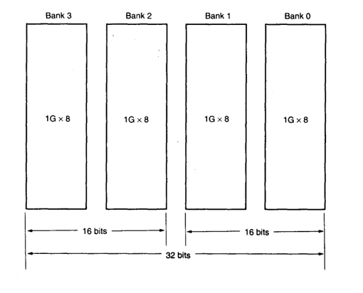
The memory is divided into four 8-bit wide memory banks, each containing up to IG bytes of memory.
This 32-bit wide memory organization allows bytes, words, or double words of memory data to access directly.
The 80386 transfers up to a 32-bit wide number in a single memory cycle, whereas the early 8088 requires four cycles to accomplish the same transfer, and the 80286 and 80386SX require two cycles.
The data width is important, especially with single-precision floating-point numbers that are 32 bits wide. High-level software normally uses floating-point numbers for data storage, so 32-bit memory locations speed the execution of high level software when it is written to take advantage of this wider memory.
In the 80386DX, the memory banks are accessed via four bank enable signals. This arrangement allows a single byte to be accessed when one bank enable signal is activated by the microprocessor.
It also allows a word to be addressed when two bank enable signals are activated. In most cases, a word is addressed in bank 0 and l or in bank 2 and 3.
The Memory location 00000000H is in bank 0, location 0000000IH is in bank 1, location 00000002H is in bank 2, and location 00000003H is in bank 3.
The memory system for 80386
80386
The figure below shows the architectural representation of 80386 microprocessor:
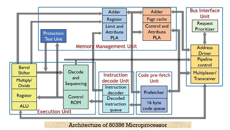
Basically it has 6 functional units which are as follows:
As we have already discussed that the 80386 possess the ability of 3 stage pipelining thus performs fetching, decoding and execution simultaneously along with memory management and bus accessing. Thus all these units operate parallely.
This pipelining technique leads to reduction in overall processing time thereby increasing the performance of the overall system.
Let us now move further and understand the operation of each unit in detail.
1. Bus Interface UnitThe bus interface unit or BIU holds a 32-bit bidirectional data bus as well as 32-bit address bus. Whenever a need for an instruction or a data fetch is generated by the system then the BIU generates signals (according to the priority) for activating the data and address bus in order to fetch the data from the desired address.
The BIU connects the peripheral devices through the memory unit and also controls the interfacing of external buses with the coprocessors.
2. Code Prefetch UnitThis unit fetches the instructions stored in the memory by making use of system buses. Whenever the system generates a need for an instruction then the code prefetch unit fetches that instruction from the memory and stores it in 16-byte prefetch queue.
So to speed up the operation this unit fetches the instructions in advance and the queue stores these instructions.
The sequence in which the instructions are fetched and gets stored in the queue depends on the order they exist in the memory.
As this unit fetches one double word in single access. So, in such a case, it is not necessary that each time only a single instruction will be fetched, as the fetched instruction can be parts of two different instructions.
It is to be noted here that, code prefetching holds lower priority than data transferring. As whenever, a need for data transfer is generated by the system then immediately the code prefetcher leaves the control over the buses. So that the BIU can transfer the required data.
But prefetching of instruction and storing it in the queue reduces the wait for the upcoming instruction to almost zero.
3. Instruction Decode UnitWe know that instructions in the memory are stored in the form of bits. So, this unit decodes the instructions stored in the prefetch queue. Basically the decoder changes the machine language code into assembly language and transfers it to the processor for further execution.
4. Execution UnitThe decoded instructions are stored in the decoded instruction queue. So, these instructions are provided to the execution unit in order to execute the instructions.
The execution unit controls the execution of the decoded instructions. This unit has a 32-bit ALU, that performs the operation over 32-bit data in one cycle. Also, it consists of 8 general purpose as well as 8 special purpose registers. These are used for data handling and calculation of offset address.
5. Memory Management UnitThis unit has two separate units within it. These are
Segmentation unit: The segmentation unit plays a vital role in the 80836 microprocessor. It offers protection mechanism in order to protect the code or data present in the memory from application programs.
It gives 4 level protection to the data or code present in the memory. Every information in the memory is assigned a privilege level from PL0 to PL3. Here, PL0 holds the highest priority and PL3 holds the lowest priority.
Suppose a file (either data or code) is needed to be accessed is stored in the memory at PL0. Then only those programs which are working at PL0 would be able to access that file. While other programs will not be able to access the same.
Also, if a file is present at PL1, then programs of PL0 and PL1 both can access it. As PL0 has higher priority than PL1. So, for protection purpose the main part of OS is stored in PL0 while PL3 holds the user programs.
Providing protection to the data or code inside the system is the most advantageous factor that was first given by 80386 microprocessor.
Paging Unit: The paging unit operates only in protected mode and it changes the linear address into physical address. As the programmer only provides the virtual address and not the physical address.
The segmentation unit controls the action of paging unit, as the segmentation unit has the ability to convert logical address into linear address at the time of executing an instruction.
Basically it changes the overall task map into pages and each page has a size of 4K. This allows the handling of task in the form of pages rather than segments.
Paging unit supports multitasking. This is so because the physical memory is not required to hold the whole segment of any task. Despite, only that part of the segment which is needed to be currently executed must be stored in that memory whose physical address is calculated by the paging unit.
This resultantly reduces the memory requirement and hence this frees the memory for other tasks. Thus,we get an effective way for managing the memory to support multitasking.
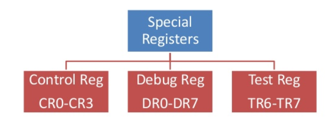
Control Registers:
CR0:
The CR0 register is 32 bits long on 80386 processor. The processor is 64 bits long. CR0 has various control flags that modify the basic operation of the processor.
Bit | Name | Full Name | Description |
31 | PG | Paging | If 1 enable paging and use CR3 register else disable paging |
30 | CD | Cache disable | Globally enable/disable the memory cache |
29 | NW | Not-write through | Globally enable/disable write back cache |
18 | AM | Alignment mask | Alignment check enabled if AM set |
16 | WP | Write protect | Determines whether CPU can write to pages marked read only |
5 | NE | Numeric error | Enable internal x87 floating point error reporting when set else enables PC style error detection |
4 | ET | Extension type | On 386 it allows to specify whether the external math coprocessor was an 80287 or 80387 |
3 | TS | Task switched | Allows saving x87 task context upon a task switch only after. |
2 | EM | Emulation | If set no x87 floating point unit present if clear x87 FPU present. |
1 | MP | Monitor co-processor | Controls interaction of WAIT/FWAIT instructions with TS flag in CR0 |
0 | PE | Protected Mode Enable | If 1 system is in protected mode else system is in real mode. |
CR1
Reserved
CR2
Contains a value called Page Fault Linear Address (PFLA) . When page fault occurs the address the program attempted to access is stored in CR2 register.
CR3
Used when virtual addressing is enabled hence when PG bit is set CR0,CR3 enables the processor to translate linear addresses into physical addresses by locating the page directory and page tables for current task. Typically the upper 20 bits of Cr3 become the page directory base register which stores the physical address of the first page directory entry.
CR4
Used in protected mode to control operations such as virtual-8086 support enabling I/O breakpoints, page size extension and machine check exceptions.
Debug Registers:
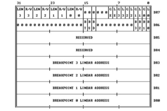
These translations are performed in a way that is not visible to applications programmers.
The Figure illustrates the two translations at a high level of abstraction.

Segment translation:
To perform this translation, the processor uses the following data structures:
- Descriptors
- Descriptor tables
- Selectors
- Segment Registers
The segment descriptor provides the processor with the data it needs to map a logical address into a linear address. Descriptors are created by compilers, linkers, loaders, or the operating system, not by applications programmers. The Figure illustrates two general descriptor formats.
All types of segment descriptors take one of these formats. Segment-descriptor fields are:
BASE: It defines the location of segment within the 4- gigabyte linear address space. The processor concatenates three fragments of the base address to form a single 32-bit value.
LIMIT: Defines the size of the segment. When the processor concatenates the two parts of the limit field, a 20-bit value results. The processor interprets the limit field in one of two ways, depending on the setting of the granularity bit:
Granularity bit: Specifies the units with which the LIMIT field is interpreted. When the bit is clear, the limit is interpreted in units of one byte; when set, the limit is interpreted in units of 4 Kilobytes.
TYPE: Distinguishes between various kinds of descriptors.
DPL (Descriptor Privilege Level): Used by the protection mechanism
Segment-Present bit: If this bit is zero, the descriptor is not valid for use in address transformation; the processor will signal an exception when a selector for the descriptor is loaded into a segment register.
The Figure shows the format of a descriptor when the present-bit is zero. The operating system is free to use the locations marked AVAILABLE. Operating systems that implement segment-based virtual memory clear the present bit in either of these cases:
Accessed bit: The processor sets this bit when the segment is accessed that is a selector for the descriptor is loaded into a segment register or used by a selector test instruction. Operating systems that implement virtual memory at the segment level may, by periodically testing and clearing this bit, monitor frequency of segment usage.
Creation and maintenance of descriptors is the responsibility of systems software, usually requiring the cooperation of compilers, program loaders or system builders, and threating system.
15 0 31 0
LOGICAL +----------------+ +-------------------------------------+
ADDRESS | SELECTOR | | OFFSET |
+---+---------+--+ +-------------------+-----------------+
+------+ ! |
| DESCRIPTOR TABLE |
| +------------+ |
| | | |
| | | |
| | | |
| | | |
| |------------| |
| | SEGMENT | BASE +---+ |
+->| DESCRIPTOR |-------------->| + |<------+
|------------| ADDRESS +-+-+
| | |
+------------+ |
!
LINEAR +------------+-----------+--------------+
ADDRESS | DIR | PAGE | OFFSET |
+------------+-----------+--------------+
General Segment-Descriptor Format
DESCRIPTORS USED FOR APPLICATIONS CODE AND DATA SEGMENTS
31 23 15 7 0
+-----------------+-+-+-+-+---------+-+-----+-+-----+-+-----------------+
| | | | |A| | | | | | | |
| BASE 31..24 |G|X|O|V| LIMIT |P| DPL |1| TYPE|A| BASE 23..16 | 4
| | | | |L| 19..16 | | | | | | |
|-----------------+-+-+-+-+---------+-+-----+-+-----+-+-----------------|
| | |
| SEGMENT BASE 15..0 | SEGMENT LIMIT 15..0 | 0
| | |
+-----------------+-----------------+-----------------+-----------------+
DESCRIPTORS USED FOR SPECIAL SYSTEM SEGMENTS
31 23 15 7 0
+-----------------+-+-+-+-+---------+-+-----+-+-------+-----------------+
| | | | |A| | | | | | |
| BASE 31..24 |G|X|O|V| LIMIT |P| DPL |0| TYPE | BASE 23..16 | 4
| | | | |L| 19..16 | | | | | |
|-----------------+-+-+-+-+---------+-+-----+-+-------+-----------------|
| | |
| SEGMENT BASE 15..0 | SEGMENT LIMIT 15..0 | 0
| | |
+-----------------+-----------------+-----------------+-----------------+
A - ACCESSED
AVL - AVAILABLE FOR USE BY SYSTEMS PROGRAMMERS
DPL - DESCRIPTOR PRIVILEGE LEVEL
G - GRANULARITY
Descriptor Tables
Segment descriptors are stored in either of two kinds of descriptor table:
- The global descriptor table (GDT)
- A local descriptor table (LDT)
A descriptor table is simply a memory array of 8-byte entries that contain descriptors, as shown in figure. A descriptor table is variable in length and may contain up to 8192 (2^(13)) descriptors.
The first entry of the GDT (INDEX=0) is not used by the processor. The processor locates the GDT and the current LDT in memory by means of GDTR and LDTR registers.
These registers store the base addresses of the tables in the linear address space and store the segment limits.
The instructions LGDT and SGDT give access to the GDTR; the instructions LLDT and SLDT give access to the LDTR.
Format of Not-Present Descriptor
31 23 15 7 0
+-----------------+-----------------+-+-----+-+-------+-----------------+
| | | | | | |
| AVAILABLE |O| DPL |S| TYPE | AVAILABLE | 4
| | | | | | |
|-----------------------------------+-+-----+-+-------+-----------------|
| |
| AVAILABLE | 0
| |
+-----------------+-----------------+-----------------+-----------------+
GLOBAL DESCRIPTOR TABLE LOCAL DESCRIPTOR TABLE
+------+-----+-----+------+ +------+-----+-----+------+
| | | | | | | | | |
|------+-----+-----+------| |------+-----+-----+------|
| | | M | | | M
+------------+------------+ +------------+------------+
| | | |
| | | |
+------+-----+-----+------+ +------+-----+-----+------+
| | | | | | | | | |
|------+-----+-----+------| |------+-----+-----+------|
| | | N + 3 | | | N + 3
|------+-----+-----+------| |------+-----+-----+------|
| | | | | | | | | |
|------+-----+-----+------| |------+-----+-----+------|
| | | N + 2 | | | N + 2
|------+-----+-----+------| |------+-----+-----+------|
| | | | | | | | | |
|------+-----+-----+------| |------+-----+-----+------|
| | | N + 1 | | | N + 1
|------+-----+-----+------| |------+-----+-----+------|
| | | | | | | | | |
|------+-----+-----+------| |------+-----+-----+------|
| | | N | | | N
+------------+------------+ +------------+------------+
| | | |
| | | |
+------+-----+-----+------+ +------+-----+-----+------+
| | | | | | | | | |
|------+--(UNUSED)-+------| |------+-----+-----+------|
| | | | | |
+------------+------------+ +------------+------------+
^ ^
+---------------------+ | +---------------------+ |
| GDTR |--+ | LDTR |--+
+---------------------+ +---------------------+
Selectors
The selector portion of a logical address identifies a descriptor by specifying a descriptor table and indexing a descriptor within that table. Selectors may be visible to applications programs as a field within a pointer variable, but the values of selectors are usually assigned (fixed up) by linkers or linking loaders. The format of selector is shown in figure.
Index:
It selects one of 8192 descriptors in a descriptor table. The processor simply multiplies this index value by 8 and adds the result to the base address of the descriptor table in order to access the appropriate segment descriptor in the table.
Table Indicator:
It specifies to which descriptor table the selector refers. A zero indicates the GDT a one indicates the current LDT.
Requested Privilege Level:
Used by the protection mechanism. Because the first entry of the GDT is not used by the processor, a selector that has an index of zero and a table indicator of zero which can be used as a null selector.
The processor does not cause an exception when a segment register (other than CS or SS) is loaded with a null selector. It will, however, cause an exception when the segment register is used to access memory. This feature is useful for initializing unused segment registers to trap accidental references.
15 4 3 0
+-------------------------+-+---+
| |T| |
| INDEX | |RPL|
| |I| |
+-------------------------+-+---+
TI - TABLE INDICATOR
RPL - REQUESTOR'S PRIVILEGE LEVEL
Segment Registers
16-BIT VISIBLE
SELECTOR HIDDEN DESCRIPTOR
+----------------+----------------------------------------+
CS | | |
|----------------+----------------------------------------|
SS | | |
|----------------+----------------------------------------|
DS | | |
|----------------+----------------------------------------|
ES | | |
|----------------+----------------------------------------|
FS | | |
|----------------+----------------------------------------|
GS | | |
+----------------+----------------------------------------+
The 80386 stores information from descriptors in segment registers, thereby avoiding the need to consult a descriptor table every time it accesses memory.
Every segment register has a "visible" portion and an "invisible" portion, as shown in the figure . The visible portions of these segment address registers are manipulated by programs as if they were simply 16-bit registers. The invisible portions are manipulated by the processor.
The operations that load these registers are normal program instructions. These instructions are of two classes:
Using these instructions, a program loads the visible part of the segment register with a 16-bit selector. The processor automatically fetches the base address, limit, type, and other information from a descriptor table and loads them into the invisible part of the segment register.
An 8086 program runs in this environment as part of V86 (virtual 8086) task. V86 tasks take advantage of the hardware support of multitasking offered by the protected mode. There can be multiple V86 tasks, each one executing an 8086 program, but V86 tasks can be multi-programmed with other 80386 tasks.
The purpose of a V86 task is to form a "virtual machine" with which to execute an 8086 program. A complete virtual machine consists not only of 80386 hardware but also of systems software. Thus, the emulation of an 8086 is the result of cooperation between hardware and software:
Software that helps implement virtual 8086 machines is called a V86 monitor.
Addressing this extended section of the memory system requires a change to the segment plus an offset addressing scheme used with real mode memory addressing.
When data and programs are addressed in extended memory, the offset address is still used to access information located within the memory segment.
In place of the segment address, the segment register contains a selector that selects a descriptor from a descriptor table. The descriptor describes the memory segment’s location, length, and access rights.
Because the segment register and offset address still access memory, protected mode instructions are identical to real mode instructions.
Most programs written to function in the real mode will function without change in the protected mode. The difference between modes is in the way that the segment register is interpreted by the microprocessor to access the memory segment.
Another difference, in the 80386 and above, is that the offset address can be a 32-bit number instead of a 16-bit number in the protected mode. A 32-bit offset address allows the microprocessor to access data within a segment that can be up to 4G bytes in
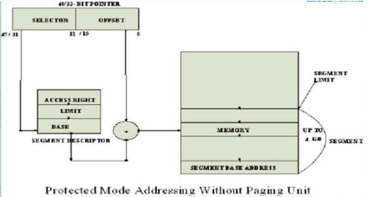
Intel386Dx uses two level table mechanism to convert linear address to physical address.
The components in paging mechanism are:
- Page Directory
- Page table
- Page frame
The page size of Intel 80386 is 4KB.
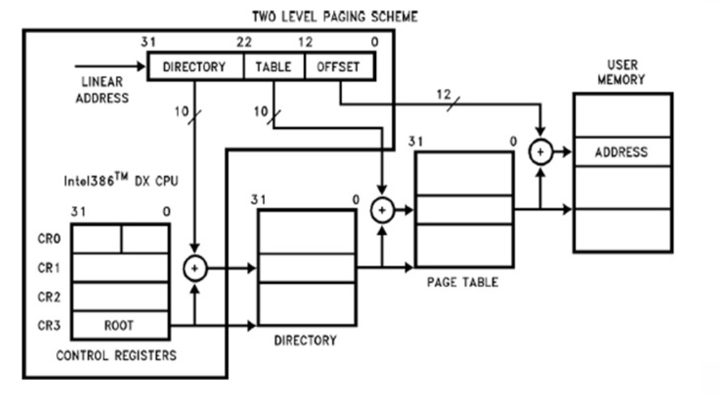
Page Descriptor Base Register

Page Directory:

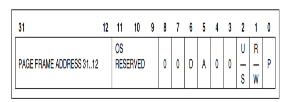
Page Table Entry
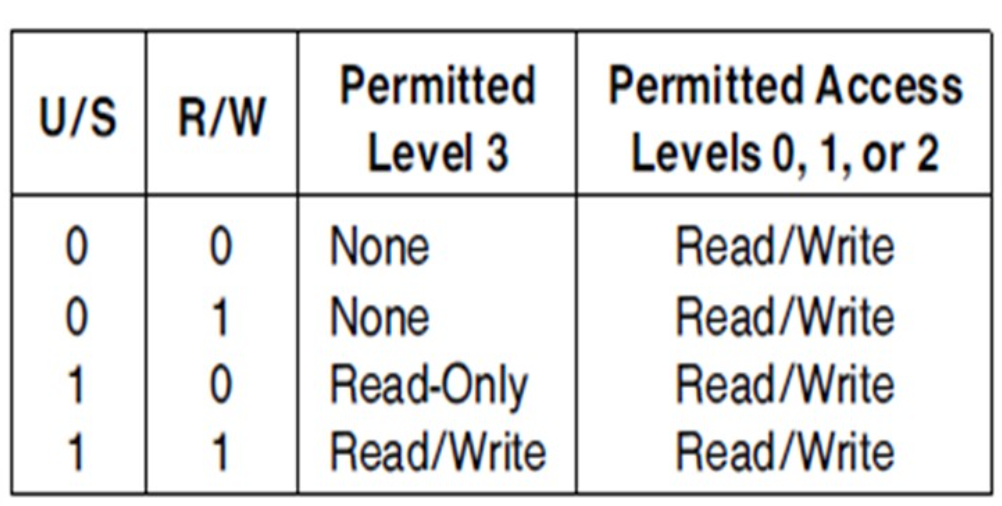
They are used to provide page level or page table level protection. They are decoded as
Supervisor level(U/S=0) for operating system and other system software and related data.
User level (U/S=1) -for application procedures and data.
Read only access (R/W =0)
Read/write access (R/W=1)
(R/W , U/S bits )
References
1. Microprocessor Architecture, Programming, and Applications with the 8085 Textbook by Ramesh S. Gaonkar
2. Microprocessor Book by A.P.Godse and D.A.Godse
3. Microprocessor And Microcontroller Book by A.P.Godse
