Unit 2
Microprocessor and its Architecture

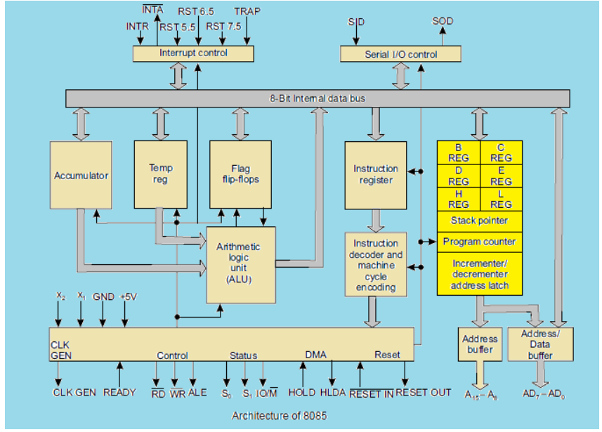
Generally, microprocessor consists of different working units which are:
Registers:
Register are vital unit and these registers are used for different purpose. Mainly registers are three types
General Purpose Registers are B, C, D, E, H& L. All are 8-bit registers. It can be used singly or can be used as 16 bit register pairs like BC, DE, HL. H & L can be used as a data pointer which holds memory address, but it cannot make pair like BE, DC. So, it should be in pair like BC, DE, HL.
Special Purpose Registers:
In 8085 microprocessor the special purpose registers are:
Accumulator stores 8-bit data in size. All arithmetic and logical operation are done inside the accumulator and after execution store the result of an operation. It also used to store 8- bit data during I/O transfer.
Flag is a brain of a microprocessor which is 8- bit register. It shows the status of the microprocessor before and after an operation.
8085 has five flags those are S (sign flag), Z (zero flag), AC (auxiliary carry flag), P (parity flag) & CY (carry flag).

Program counter is a special purpose register. This register is used to control the sequencing of the execution of instructions. This register always holds the address of the next instruction. Since it holds an address so it must be 16- bit register.
The stack pointer is used as an address pointer. The stack pointer is also a 16-bit register that is used to point into memory. The memory this register points to be a special area called the stack. The stack is an area of memory used to hold data that which will be retrieved soon. The stack is usually accessed in a Last in First Out (LIFO) fashion.
TIMING & CONTROL UNIT:
The timing and control unit synchronizes all the microprocessor operations with the clock and generates the control signals necessary for communication between the microprocessor and peripherals.
INSTRUCTION REGISTER & DECODER:
When an instruction is fetched from memory it is placed in instruction register. Then it is decoded and encoded into various machine cycles.
(a)Data Addressing Mode:
The data-addressing modes include
Data-Addressing Modes
Because the MOV instruction is a common and flexible instruction, it provides a basis for the explanation of the data-addressing modes. Figure 3-1 illustrates the MOV instruction and defines the direction of data flow. The source is to the right and the destination is to the left, next to the opcode MOV. An opcode, or operation code, tells the microprocessor which operation to perform.
In Figure, the MOV AX,BX instruction transfers the word contents of the source register (BX) into the destination register (AX). The source never changes, but the destination usually changes.1 It is essential to remember that a MOV instruction always copies the source data and into the destination. The MOV never actually picks up the data and moves it. Also, note that the flag register remains unaffected by most data transfer instructions. The source and destination are often called operands.

An instruction showing the destination and the source
The data-addressing modes are as follows:
Register Addressing
Register addressing is the most common form of data addressing. The microprocessor contains the following 8-bit registers used with register addressing: AH, AL, BH, BL, CH, CL, DH, and DL.
The following 16-bit registers are AX, BX, CX, DX, SP, BP, SI, and DI.
In the 80386 and above, the extended 32-bit registers are EAX, EBX, ECX, EDX, ESP, EBP, EDI, and ESI. With register addressing, some MOV instructions, and the PUSH and POP instructions, also use the 16-bit segment registers (CS, ES, DS, SS, FS, and GS).
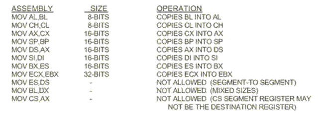
The Table shows some variations of register move instructions. It is impossible to show all combinations because there are too many. A segment-to-segment register MOV instruction is not allowed.


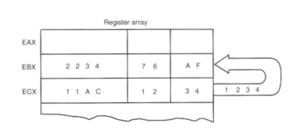
The operation of the MOV BX,CX instruction. Note that the source register’s contents do not change, but the destination register’s contents do change. The instruction copies a 1234H from register CX into register BX. This erases the old contents (76AFH) of register BX, but the contents of CX remain unchanged. The contents of the destination register or destination memory location change for all instructions except the CMP and TEST instructions. Note that the MOV BX, CX instruction does not affect the leftmost 16 bits of register EBX.
Immediate Addressing
The term immediate implies that the data immediately follow the hexadecimal opcode in the memory. The immediate data are constant data, while the data transferred from a register are variable data.
Immediate addressing operates upon a byte or word of data.
In the 80386 immediate addressing also operates on doubleword data.
The MOV immediate instruction transfers a copy of the immediate data into a register or a memory location.
The figure shows the operation of a MOV EAX,13456H instruction. This instruction copies the 13456H from the instruction, located in the memory immediately following the hexadecimal opcode, into register EAX.
As with the MOV instruction illustrated in Figure the source data overwrites the destination data.

Direct Data Addressing
In fact, direct data addressing is applied to many instructions in a typical program. There are two basic forms of direct data addressing:
1.Direct addressing, which applies to a MOV between a memory location and AL, AX, or EAX, and
2.Displacement addressing, which applies to almost any instruction in the instruction set.
In either case, the address is formed by adding the displacement to the default data segment address or an alternate segment address.
Direct Addressing:
Direct addressing with a MOV instruction transfers data between a memory location, located within the data segment, and the AL (8-bit), AX (16-bit), or EAX (32-bit) register.
A MOV instruction using this type of addressing is usually a 3-byte long instruction.
The MOV AL, DATA instruction is represented by most assemblers which loads AL from data segment memory location DATA (1234H). Memory location DATA is a symbolic memory location, while the 1234H is the actual hexadecimal location.
The Table lists the three direct addressed instructions. These instructions often appear in programs. All other instructions that move data from a memory location to a register, called displacement-addressed instructions that require four or more bytes of memory for storage in a program.
Displacement Addressing: Displacement addressing is identical to direct addressing, except that the instruction is four bytes wide instead of three.
If the operation of the MOV CL,DS:[l234H] instruction is compared to that of the MOV AL,DS: [I 234Hj instruction both basically perform the same operation except for the destination register (CL versus AL).
The SMALL model allows one data segment and one code segment. The SMALL model is often used whenever memory data are required for a program. A SMALL model program assembles as an execute (.EXE) program.
Register Indirect Addressing
Register indirect addressing allows data to be addressed at any memory location through an offset address held in any of the following registers: BP, BX, DI, and SI.
For example, if register BX contains a l000H and the MOV AX,[BX] instruction executes, the word contents of data segment offset address I 000H are copied into register AX.
If the microprocessor is operated in the real mode and DS = OIOOH, this instruction addresses a word stored at memory bytes 2000H and 2001H, and transfers it into register AX . Note that the contents of 2000H are moved into AL and the contents of 2001H are moved into AH.
Base-Plus-Index Addressing
Base-plus-index addressing is similar to indirect addressing because it indirectly addresses memory data. In the 8086 through the 80286, this type of addressing uses one base register (BP or BX), and one index register (DI or SI) to indirectly address memory. The base register often holds the beginning location of a memory array, while the index register holds the relative position of an element in the array
Register Relative Addressing
Register relative addressing is similar to base-plus-index addressing and displacement addressing.
In register relative addressing, the data in a segment of memory are addressed by adding the displacement to the contents of a base or an index register (BP, BX, DI, or SI).
Consider MOV AX,[BX+l000I-I] instruction.
In this example, BX = OlOOH and DS = 0200H, so the address generated is the sum of DS x 101-I, BX, and the displacement of L000H or 03100H. Remember that BX, DI, or SI addresses the data segment and BP addresses the stack segment.
In the 80386 and above, the displacement can be a 32-bit number and the register can be any 32-bit register except the ESP register.
Base Relative-Plus-Index Addressing
The base relative-plus-index addressing mode is similar to the base-plus-index addressing mode. but it adds a displacement, besides using a base register and an index register, to form the memory address. This type of addressing mode often addresses a two-dimensional array of memory data.
Scaled-Index Addressing
Scaled-index addressing uses two 32-bit registers (a base register and an index register) to access the memory. The second register (index) is multiplied by a scaling factor. The scaling factor can be JX, 2X, 4X, or 8X. A scaling factor of lX is implied and need not be included in the assembly language instruction (MOV AL,[EBX+ECX]).
A scaling factor of 2X is used to address word-sized memory arrays, a scaling factor of 4X is used with doubleword-sized memory arrays, and a scaling factor of 8X is used with quadword-sized memory arrays.
Consider MOV AX,[EDI+2*ECXj. This instruction uses a scaling factor of 2X, which multiplies the contents of ECX by 2 before adding it to the EDI register to form the memory address. If ECX contains a 00000000H, word-sized memory element 0 is addressed; if ECX contains a 0000000 1H, word-sized memory element 1 is accessed, and so forth. This scales the index (ECX) by a factor of 2 for a word-sized memory array.
(b) PROGRAM MEMORY-ADDRESSING MODES
Program memory-addressing modes are used with the iMP and CALL instructions, consist of three distinct forms: direct, relative, and indirect.
Direct Program Memory Addressing
The microprocessor uses this form of addressing, but not as often as relative and indirect program memory addressing are used.
The instructions for direct program memory addressing store the address with the opcode.
For example, if a program jumps to memory location 1000011 for the next instruction, the address (10000H) is stored following the opcode in the memory.
It shows the direct intersegment iMP instruction and the four bytes required to store the address 1000011. This IMP instruction loads CS with 100011 and IP with 000011 to jump to memory location 1000011 for the next instruction. (An intersegment jump is a jump to any memory location within the entire memory system.)
The direct jump is often called afar jump because it can jump to any memory location for the next instruction.
In the real mode, a farjump accesses any location within the first IM byte of memory by changing both CS and IP.
In protected mode operation, the far jump accesses a new code segment descriptor from the descriptor table, allowing it to jump to any memory location in the entire 4G-byte address range in the 80386 through Pentium II microprocessors.
The only other instruction that uses direct program addressing is the intersegment or far CALL instruction. Usually, the name of a memory address, called a label, refers to the location that is called or jumped to instead of the actual numeric address. When using a label with the CALL or JMP instruction, most assemblers select the best form of program addressing.
Relative Program Memory Addressing
The term relative means “relative to the instruction pointer (IP).” For example, if a JMP instruction skips the next two bytes of memory, the address in relation to the instruction pointer is a 2 that adds to the instruction pointer. This develops the address of the next program instruction.
The IMP instruction is a one-byte instruction, with a one-byte or a two-byte displacement that adds to the instruction pointer.
A one-byte displacement is used in short jumps, and a two-byte displacement is used with near jumps and calls. Both types are intra-segment jumps.
Relative JMP and CALL instructions contain either an 8-bit or a 16-bit signed displacement that allows a forward memory reference or a reverse memory reference.
An 8-bit displacement (short) has a jump range of between +127 and —128 bytes from the next instruction, while a 16-bit displacement (near) has a range of ±32K bytes.
In the 80386 and above, a 32-bit displacement allows a range of ±2G bytes. The 32-bit displacement can only be used in the protected mode.
indirect Program Memory Addressing
The microprocessor allows several forms of program indirect memory addressing for the JMP and CALL instructions. Some of the acceptable program indirect jump instructions, which can use any 16-bit register (AX, BX, CX, DX. SP, BP, DI, or SI); any relative register ([BP], [BX], [DI], or [SI]); and any relative register with a displacement.
If a 16-bit register holds the address of a JMP instruction, the jump is near. For example, if the BX register contains a I000H and a JMP BX instruction executes, the microprocessor jumps to offset address 100011 in the current code segment.
If a relative register holds the address, the jump is also considered to be an indirect jump. For example, a IMP [BXj refers to the memory location within the data segment at the offset address contained in BX. At this offset address is a 16-bit number that is used as the offset address in the intrasegment jump. This type of jump is sometimes called an indirect-indirect or double-indirect jump.
STACK MEMORY-ADDRESSING MODES
The stack memory is a LIFO (last-in, first-out) memory, which describes the way that data are stored and removed from the stack. Data are placed onto the stack
with a PUSH instruction and removed with a POP instruction.
The CALL instruction also uses the stack to hold the return address for procedures and a RET (return) instruction to remove the return address from the stack.
The stack memory is maintained by two registers: the stack pointer (SP or ESP) and the stack segment register (SS).
Whenever a word of data is pushed onto the stack the high-order 8 bits are placed in the location addressed by SP — 1.
The low-order 8 bits are placed in the location addressed by SP — 2. The SP is then decremented by 2 so that the next word of data is stored in the next available stack memory location.
The SP/ESP register always points to an area of memory located within the stack segment. The SPIESP register adds to SS x IOH to form the stack memory address in the real mode. In protected mode operation, the SS register holds a selector that accesses a descriptor for the base address of the stack segment.
Whenever data are popped from the stack the low-order 8 bits are removed from the location addressed by SP. The high-order 8 bits are removed from the location addressed by SP + 1.
PUSH and POP instructions available to the microprocessor. Note that PUSH and POP always store or retrieve words of data never bytes in the 8086 through the 80286 microprocessors.
The PUSHA and POPA instructions either push or pop all of the registers, except the segment registers, on the stack. These instructions are not available on the early 8086/8088 microprocessors. The push immediate instruction is also new to the 80286 through the Pentium microprocessors.
References
1. Microprocessor Architecture, Programming, and Applications with the 8085 Textbook by Ramesh S. Gaonkar
2. Microprocessor Book by A.P.Godse and D.A.Godse
3. Microprocessor And Microcontroller Book by A.P.Godse