Streaming of recorded audio and video is the first one. The downloading of these file types from a Web server will differ from the downloading of other file types.
Let us explore four methods, each with a different complexity, to understand the idea.
6.1.1 First approach : Using a web server
It's possible to download a compressed audio/video file as a text file. The client (browser) will use HTTP services and send a GET message for the file to be downloaded. The compressed file can be sent by the Web server to the browser. In order to play the video, the browser will then use a support programme, usually called a media player.
This technique is really quick and does not require streaming. It has a downside, however. Even after compression, an audio/video file is typically huge. There can be tens of megabits in an audio file, and a video file can contain hundreds of megabits. In this technique, the file needs to be fully downloaded before it can be played. The user requires several seconds or tens of seconds before the file can be played, using contemporary data rates.
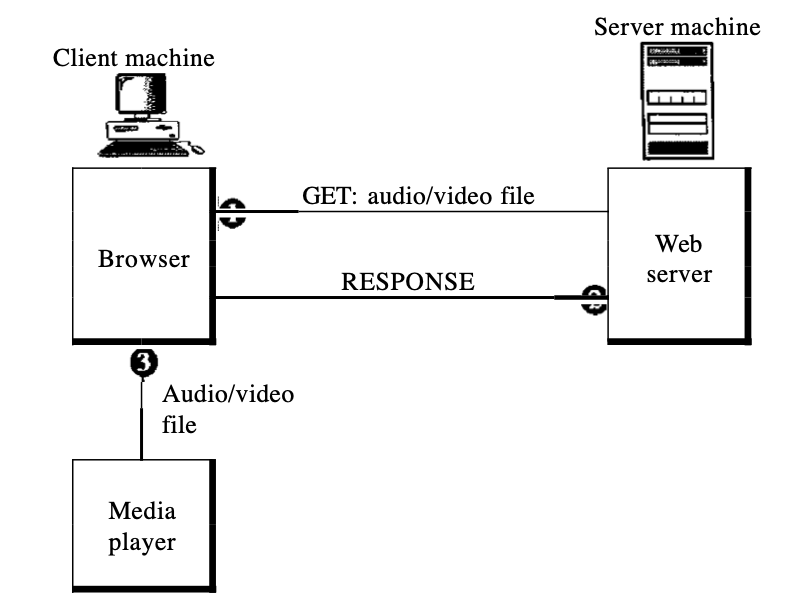
Fig 1: using a web server
6.1.2 Second approach : Using a web server with metafile
In another method, for downloading the audio/video file, the media player is linked directly to the Web server. Two files are stored by the Web server: the actual audio/video file and a metafile containing audio/video file information.
1. Through using the GET message, the HTTP client accesses the Web server.
2. In the answer, details about the metafile comes in.
3. It moves the metafile to the media player.
4. To access the audio/video file, the media player uses the URL in the metafile.
5. The server on the Site reacts.
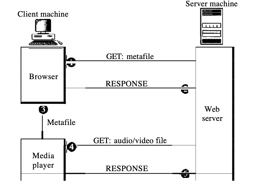
Fig 2: web server with metafile
6.1.3 third approach : Using a media server
The issue with the second solution is that both the browser and the media player use HTIP's services. HTIP is intended for running over TCP. This is suitable for metafile retrieval, but not for audio/video file retrieval. The explanation is that a missing or disabled segment is retransmitted by TCP, which is contrary to the streaming philosophy.
TCP and its error management must be ignored. We need to use UDP. HTTP, which accesses the Web server, and the Web server itself are configured for TCP, so we need another server, a media server.
1. Through using a GET post, the HTTP client accesses the Web server.
2. In the answer, details about the metafile comes in.
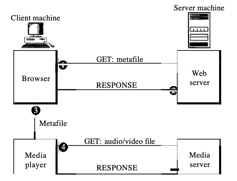
Fig 3: media server
6.1.4 Fourth approach : Using a media server and RTSP
The Real-Time Streaming Protocol (RTSP) is a control protocol designed to provide more functionality to the streaming process. We can monitor the playing of audio/video by using RTSP. RTSP is a protocol of out-of-band control close to the second link in FTP.
In the below diagram, we have :
1. The HTTP client accesses the Web server using a GET message.
2. The information about the metafile comes in the response.
3. The metafile is passed to the media player.
4. The media player sends a SETUP message to create a connection with the media server.
5. The media server responds.
6. The media player sends a PLAY message to start playing (downloading).
7. The audio/video file is downloaded using another protocol that runs over UDP.
8. The connection is broken using the TEARDOWN message.
9. The media server responds.
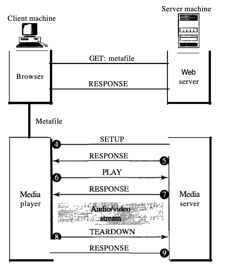
Fig 4: media server and RTSP
Other kinds of messages can be received by the media player. For instance, a PAUSE message momentarily stops downloading; a PLAY message can be used to resume downloading.
Key takeaway :
● Stored audio/video streaming refers to requests for compressed audio/video files on demand.
● The compressed file can be sent by the Web server to the browser. In order to play the video, the browser will then use a support programme, usually called a media player.
● In second method, for downloading the audio/video file, the media player is linked directly to the Web server.
● We need to use UDP. HTTP, which accesses the Web server, and the Web server itself are configured for TCP, so we need another server, a media server.
● The Real-Time Streaming Protocol (RTSP) is a control protocol designed to provide more functionality to the streaming process.
A consumer listens to broadcast audio and video through the Internet in the second category, live audio/video streaming.
Live audio/video streaming is similar to radio and TV stations' transmission of audio and video. The stations transmit over the Internet, instead of broadcasting on the air. Between streaming stored audio/video and streaming live audio/video, there are many parallels. Both of them are delay-sensitive; neither will accept retransmission. There is a distinction, however. The contact in the first application is unicast and on-demand.
The contact in the second is multicast and live. Live streaming is best suited to IP multicast services and the use of UDP and RTP protocols. Live streaming is still, however, currently using TCP and multiple unicasting instead of multicasting. A great deal of progress still needs to be made in this region.
Key takeaway :
● Live audio/video streaming refers to the broadcasting of radio and TV programmes through the Internet.
● Internet radio offers a good example of this form of application.
In real-time interactive audio/video, people communicate in real time with each other. An example of this type of application is the Internet phone or voice over IP. Another example that enables people to communicate visually and verbally is video conferencing.
Characteristics : We are discussing several features of real-time audio/video communication before addressing the protocols used in this class of applications.
● Time relationship :
The protection of the time relationship between a session's packets includes real-time data on a packet-switched network. For instance, let us assume that live video images are generated and sent online by a real-time video server. It digitises and packs the video. Only three packets are available, and each packet contains video information lOs.
The first packet begins at 00:00:00, the second packet begins at 00:00:10 and the third packet begins at 00:00:20, respectively. Imagine that for each packet to enter the destination it takes 1 s (an exaggeration for simplicity) (equal delay). The first packet can be played back by the receiver at 00:00:01, the second at 00:00:11, and the third at 00:00:21. Although there is a time gap between what the server sends and what the client sees on the screen of the machine, the action takes place in real time.
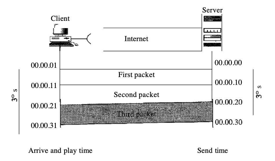
Fig 5: time relationship
● Time stamp :
The use of a timestamp is one form of jittering. If and packet has a timestamp showing the time it was produced relative to the first (or previous) packet, then this time can be applied by the receiver to the time when the playback begins. The receiver knows, in other words, when each packet is to be played.
In the previous example, assume the first packet has a timestamp of 0, the second has a timestamp of 10, and the third has a timestamp of 20. If the receiver begins playing the first pack at 00:00:08, the second packet is played at 00:00:18 and the third packet is played at 00:00:28. The packets do not have gaps between them.
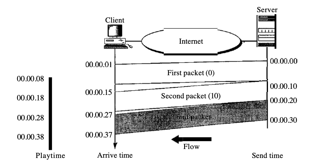
Fig 6: time stamp
● Playback buffer :
In order to be able to distinguish the arrival time from the playback time, before they are played back, we need a buffer to store the data. The buffer is referred to as a buffer for playback.
The first bit of the first packet arrives at 00:00:01 in the previous example; the threshold is 7 s, and the replay time is 00:00:08. The threshold is calculated by data time units. The replay does not start until the data units of time are equal to the value of the threshold.
Data is stored at a theoretically variable rate in the buffer, but at a constant rate they are retrieved and played back. Notice that the amount of data in the buffer shrinks or expands, but there is no jitter as long as the delay is smaller than the time to play back the data amount threshold.
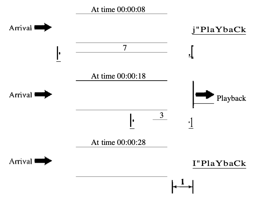
Fig 7: playback buffer
● Ordering :
One more feature is required, in addition to time relationship information and timestamps for real-time traffic. For each packet, we need a sequence number. If a packet is lost, the timestamp alone does not notify the recipient. Suppose the timestamps are 0, 10, and 20, for instance.
Just two packets with timestamps 0 and 20 are received by the recipient. The receiver assumes that the packet is the second packet with time stamp 20, generated 20s after the first. The recipient has no way of knowing that they have already misplaced the second packet. To handle this, a sequence number is required to order the packets.
Scenario.
● Multicasting :
In audio and video conferencing, multimedia plays a primary function. Traffic can be high, and by using multicasting techniques, the data is distributed.
Two-way communication between receivers and senders is needed for conferencing.
● Translation :
Real-time traffic requires translation often. A converter is a device that can modify the video signal format of a high-bandwidth video signal to a narrow-bandwidth signal of lower quality. For example, this is necessary for a source that produces a high-quality video signal at 5 Mbps and sends it to a recipient with a bandwidth of less than 1 Mbps. A translator is required to decode the signal and encode it again at a lower quality that requires less bandwidth in order to receive the signal.
● Mixing :
If there is more than one source that can concurrently send data (as in a video or audio conference), several sources are made up of traffic. Data from various sources can be combined to convert the traffic to one stream. To produce a single signal, a mixer mathematically adds signals originating from various sources.
● Support from transport layer protocol :
In the preceding parts, the procedures mentioned can be applied in the
Layer for application. In real-time applications, however, they are so popular that It is preferable to incorporate them in the transport layer protocol. Let's see which of the current layers of transport is sufficient for this kind of traffic.
For interactive traffic, TCP is not suitable. It has no provision for timestamping, and it does not allow multicasting. It does, however, have ordering (sequence numbers). Its error control mechanism is one feature of TCP that makes it especially unsuitable for interactive traffic.
For interactive multimedia traffic, UDP is more fitting. UDP supports multicasting and has no plan for retransmission. However, for time stamping, sequencing, or combining, UDP has no provision. These missing features are provided by a new transport protocol, the Real-Time Transport Protocol (RTP).
Key takeaway :
● We may time-stamp the packets and separate the time of arrival from the playback time to avoid jitter.
● For real-time traffic, a playback buffer is needed.
● For real-time traffic, a sequence number on every packet is needed.
● Real-time traffic requires multicasting support.
● To fit the bandwidth of the receiving network, translation requires adjusting the encoding of a payload to a lower standard.
● Mixing means mixing multiple traffic sources into one stream.
● For interactive multimedia traffic, TCP, with all its complexity, is not suitable because we can not allow packet retransmission.
● For interactive traffic, UDP is more fitting than TCP. However, to compensate for the UDP deficiencies, we need the services of RTP, another transport layer protocol.
The RTP (Real-time Transport Protocol) is a protocol designed to manage Internet traffic in real-time. There is no distribution method for RTP (multicasting, port numbers, etc.); it has to be used with UDP.
RTP stands between UDP and the software for the submission. Time-stamping, sequencing, and mixing facilities are RTP's core contributions.
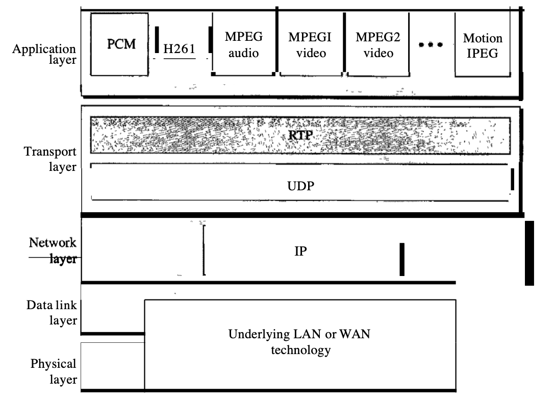
Fig 8: RTP
6.4.1 RTP packet format
To cover all real-time applications, the format is very simple and general enough. An application that needs more data adds it to the start of its payload. It follows a definition of each sector.
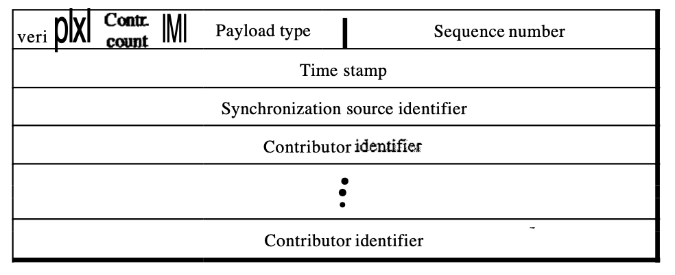
Fig 9: packet format
● Ver : This 2-bit field defines the version number.
● P : If set to 1, this 1-bit field indicates the presence of padding on the end of the packet. If the P field value is 0, there is no padding.
● X : When set to 1, this 1-bit field indicates an additional extension header between the basic header and the data. When the value of this field is 0, there is no extra extension header.
● Contributor count : The number of contributors indicates this 4-bit area. Note that we can have a maximum of 15 contributors, as only a number between 0 and 15 is allowed in a 4-bit region.
● M : This 1-bit field is a marker that the application uses, for instance, to indicate the end of its data.
● Payload type : The type of the payload is indicated by this 7-bit sector. So far, multiple payload types have been identified.
● Sequence number : This field has a length of 16 bits. It is used to number the packets of the RTP. The first packet's sequence number is selected at random; for each subsequent packet, it is incremented by 1. The sequence number is used to detect missing or out of order packets by the recipient.
● Time stamp : This is a 32-bit field showing the relationship of time between packets.
● Synchronization source identifier : If only one source exists, the source is described by this 32-bit field. Furthermore, The mixer is the source of synchronisation if there are many sources and the other sources are contributors. A random number selected by the source is the value of the source identifier.
● Contributor identifier : A source is identified by each of these 32-bit identifiers (a maximum of 15). When there is more than one source in a session, the synchronisation source is the mixer and the participants are the remaining sources.
6.4.2 UDP port
While RTP is a transport layer protocol itself, an IP datagram does not encapsulate the RTP packet directly. Instead, RTP is viewed as an application programme and is encapsulated in a datagram of the UDP user. However, no well-known port is allocated to RTP, unlike other application programmes.
On request, the port can be selected with only one restriction: the port number must be an even number. The next number (an odd number) is used by the Real-Time Transport Control Protocol companion of RTP.
Key takeaway :
● RTP is a protocol designed to manage Internet traffic in real-time.
● RTP stands between UDP and the software for the submission.
● RTP is viewed as an application programme and is encapsulated in a datagram of the UDP user.
Only one form of message is allowed by RTP, one that carries data from the source to the destination. There is a need for other messages in a session in many situations. The data flow and quality are managed by these messages and allow the recipient to send feedback to the source or sources.
A protocol built for this purpose is the Real-Time Transport Control Protocol (RTCP). RTCP contains five types of With texts. The number next to each box will identify the message type.
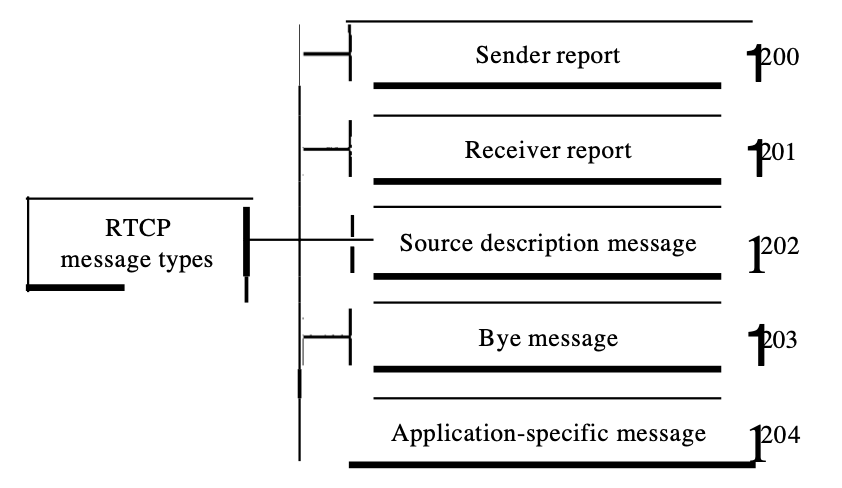
Fig 10 : RTPC
6.5.1 Types of message
● Sender report : The sender report is submitted annually by the active senders in a conference to report transmission and receipt statistics for all RTP packets sent during the interval.
● Receiver report : For passive participants, the receiver report is those who don't send RTP packets. The report tells about the level of service to the sender and other receivers.
● Source Description message : The source sends a source summary message regularly to give it more information about itself.
● Bye message : To shut down a stream, a source sends a bye message. This enables the source to declare that it is leaving the meeting.
● Application - specific message : For an application that needs to use new applications, the application-specific message is a packet (not defined in the standard). This enables the description of a new form of message.
6.5.2 UDP port
RTCP does not use a well-known UDP port, as does RTP. A temporary port is used. The chosen UDP port must be the number immediately following the selected UDP port for RTP, making it an odd-numbered port.
Key takeaway :
● RTCP uses an odd-numbered UDP port number which follows the selected RTP port number.
● RTCP contains five types of With texts. The number next to each box will identify the message type.
● RTCP does not use a well-known UDP port, as does RTP.
The idea is to use the Internet, with some added capabilities, as a telephone network. This programme allows contact between two parties over the packet-switched Internet, instead of communicating over a circuit-switched network.
Two protocols were developed to deal with this kind of Communication:
SIP(Session Initiation Protocol) and H.323
The Session Initiation Protocol (SIP) is an application layer protocol established by IETE that creates, manages and terminates a multimedia session (call). Two-party, multiparty, or multicast sessions can be generated using it.
SIP is built to be independent of the underlying transport layer; UDP, TCP, or SCTP may be used.
Message :
SIP is a protocol based on text, and so is HTTP. SIP uses messages, as does HTTP. There are six specified messages.
There is a header and a body in each post. The header consists of several lines which describe the message structure, the capacity of the caller, media type, and so on.

Fig 11: SIP message
● A session with the INVITE message is initialised by the caller.
● The caller sends an ACK message for clarification after the caller answers the call.
● A session is terminated by a BYE call.
● The OPTIONS message asks about the capabilities of a computer.
● The CANCEL message cancels an initialization process which has already begun.
● When the callee is not available, the REGISTER message allows a connection.
Address
A telephone number identifies the sender in a periodic telephone correspondence, and another telephone number identifies the recipient. SIP is very versatile. To distinguish the sender and recipient, an e-mail address, an IP address, a telephone number, and other types of addresses may be used in SIP. The address needs to be in SIP format, though (also called scheme).

Fig 12: SIP address format
Simple sessions
Three modules consist of a basic session using SIP: Establish , Communicating, and terminating.
● Establish a session : It takes a three-way handshake to create a session in SIP. Using UDP, TCP, or SCTP to start contact, the caller sends an INVITE request. She sends a response message if the caller is ready to start the session.
● Communicating : The caller and the callee will communicate by using two temporary ports after the session has been created.
● Terminating the session : With a BYE message sent by either side, the session can be terminated.
Tracking the callee
What happens if there isn't a callee sitting in her terminal? She might be away or at another terminal from her system. If DHCP is being used, she does not even have a set IP address. SIP has a function that seeks the IP address of the terminal at which the callee is sitting (similar to one in DNS). SIP uses the idea of registration to do this monitoring. Some servers are specified by SIP as registrars. A user is registered with at least one registrar server at any time; that server knows the callee's IP address.
The caller should use the e-mail address rather than the IP address in the INVITE message when a caller wants to connect with the caller. The message goes to a server that is a proxy. The proxy server sends a search message (not part of the SIP) to the server of the registrar that registered the call. The proxy server takes the caller's INVITE message and adds the newly discovered IP address of the caller when the proxy server receives a reply message from the registrar's server. This message is sent to the callee, then.
6.7.1 H.323
H.323 is a standard developed by lTV to allow computers (called terminals in H.323) linked to the Internet to communicate to telephones on the public telephone network.
A gateway links the telephone network to the Internet. A gateway is typically a five-layer interface that can convert a message from one stack of protocols to another. The gateway does the very same thing here. It converts a message from the telephone network into an Internet message. As we mentioned in SIP, the gatekeeper server on the local area network plays the role of the registrar server.
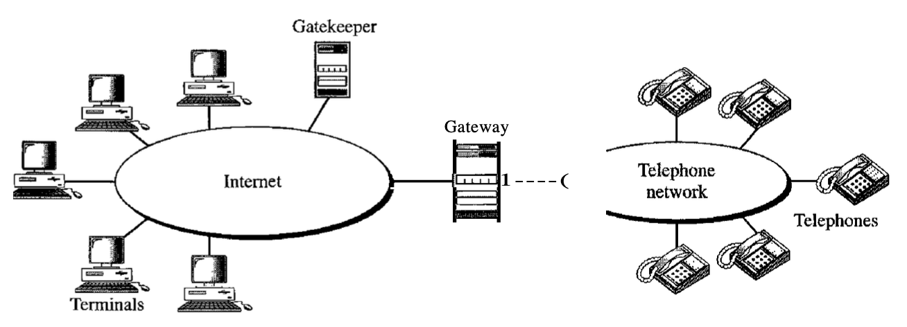
Fig 13: Architecture of H.323
Key takeaway :
● This programme allows contact between two parties over the packet-switched Internet, instead of communicating over a circuit-switched network.
● The Session Initiation Protocol is an application layer protocol established by IETE.
● SIP uses messages, as does HTTP.
● The address needs to be in SIP format.
● The proxy server sends a search message to the server of the registrar that registered the call.
References :
2. Internetworking with TCP/IP by Douglas Comer
3. Computer Networking: A Top-Down Approach by Jim Kurose