Event represents incidents that cause objects to transition from one state to another.
Internal or External Events trigger some activity that changes the state of the system
and of some of its parts. Events pass information, which is elaborated by Objects
operations. Objects realize Events.
A Trigger indicates an event that initiates an action (and might arise from completion of a previous action)
An event can be one of the following cases:
● Signal event - corresponding to the arrival of an asynchronous message or signal
● Call event - corresponding to the arrival of a procedural call to an operation
● Time event - a time event occurs after a specified time has elapsed
● Change event - a change event occurs whenever a specified condition is met
- Signal Events : Signals are asynchronous, i.e., the sender does not wait until the receiver receives the signal or reacts to it. A signal event in time is a specific occurrence.
A signal is an explicit one-way transmission of information from one object to another. The sending or receiving signal event is a signal event. It awaits recognition when an object sends a signal to another object, but the acknowledgement signal is the separate signal under the control of the second object that may or may not choose to send it.
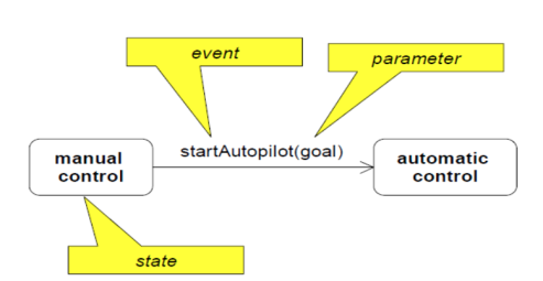
2. Call Events : Call events are synchronous, i.e., the sender waits until the receiver reacted on the event.
|
Fig 1: event
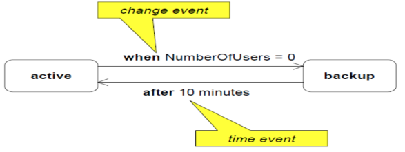
3. Time Events : A time event appears after the expiration of a time period. It is induced by the occurrence of an absolute interval of time or the elapse of time.
4. Change Events : A change event occurs if a specific constraint is fulfilled. The constraint is a Boolean expression on the attributes of the actual object. It is activated by a Boolean expression's satisfaction. The purpose of the change event is to continuously evaluate the expression if the expression changes from false to true.
|
Fig 2: time and change event
External and Internal Events
External events are those events that pass inside the system from a user of the system to the objects. For starters, the user's mouse-click or key-press are external events.
Internal events are those that pass within a device from one object to another object. Stack overload, a dividing error, etc., for instance.
Deferred Events
Deferred events are those that are not handled immediately in the current state by the object, but are lined up in a queue so that they can be handled later by the object in some other state.
Event Classes
A group of events with a similar structure and actions are indicated in the event class. Event classes can also be structured in a hierarchical system, as with classes of objects. Event types, time being an implied attribute, may have attributes associated with them.
Key takeaway :
● Event represents incidents that cause objects to transition from one state to another.
● Events pass information, which is elaborated by Objects operations.
● Internal or External Events trigger some activity that changes the state of the system and of some of its parts.
● A group of events with a similar structure and actions are indicated in the event class.
Rumbaugh defines that: “ A state is an abstraction of the attribute values and links of an object. Sets of values are grouped together into a state according to properties that affect the gross behavior of the object. ”
A state is a constraint or a situation in the life cycle of an object, in which a constraint
holds, the object executes an activity or waits for an event.
An entity changes its state not only as a direct consequence of the current input, but it is also dependent on some past history of its inputs.
A state is shown as a rounded rectangle.
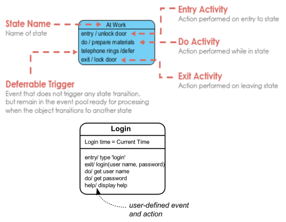
● Each state has a name, optionally state variables (i.e., attributes of the state-owning class), and optionally activities.
● Standard events in the activity compartment include entry, exit, and do
● A state can represented as below
|
Fig 3: States
● “entry/”
identifies an action, specified by the corresponding action expression, which is performed upon entry to the state (entry action)
● “exit/”
identifies an action, specified by the corresponding action expression, that is
performed upon exit from the state (exit action)
● “do/”
identifies an ongoing activity (“do activity”) that is performed as long as the
modeled element is in the state or until the computation specified by the action
expression is completed (the latter may result in a completion event being
generated).
● “include/”
is used to identify a submachine invocation. The action expression contains the
name of the submachine that is to be invoked.
The portions of a state :
Name − A string separates one state from another. A state can have no name at all.
Entry/Exit Actions-The acts conducted when entering and leaving the state are denoted.
Internal Transitions-The changes that do not cause a change in the environment within a state.
Sub-states-States within states.
Initial and Final State
● The initial state of a state machine diagram, known as an initial pseudo-state, is indicated with a solid circle. A transition from this state will show the first real estate.
● The final state of a state machine diagram is shown as concentric circles. An open loop state machine represents an object that may terminate before the system terminates, while a closed loop state machine diagram does not have a final state; if it is the case, then the object lives until the entire system terminates.
|
|
Fig 4: initial and final state
Key takeaway :
● A state is a constraint or a situation in the life cycle of an object, in which a constraint holds, the object executes an activity or waits for an event.
● A state is an abstraction of the attribute values and links of an object.
● The initial state of a state machine diagram, known as an initial pseudo-state, is indicated with a solid circle.
● The final state of a state machine diagram is shown as concentric circles.
Most clearly, operations refer to a class's processes. Operations refer to public methods on a form at the level of the specification. Normally, since they can generally be inferred, you don't display such operations that simply manipulate attributes. However, you might need to indicate whether a given attribute is read-only or frozen (that is, its value never changes). You may want to display private and secure operations in the implementation model, as well.
In different ways, each operation can be specified. They are:
- Mathematical functions, for example, trigonometric functions
- Input and output values table for tiny finite sets
- Equations which specify the output in input terms.
- Pre- and post- conditions
- Decision tables
- Pseudocode
- Natural language
An operation specification requires a signature and a transformation. An external operation specification only defines changes that are apparent outside of the operation. Access operations are those operations which read or write an object's attributes or links. It is possible to classify non trivial operations into three categories: requests, actions, and behaviours. A query is an operation that is a pure function that has no side effects.
Key takeaway :
● Operations are the procedures a class learns how to run.
● An operation specification requires a signature and a transformation.
● An operation is a feature or transformation that in a class can be applied to or by objects.
● As an implied statement, each procedure has a target object. The operation's behavior depends on the class of its target.
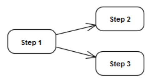
Concurrency is a property of a system in which the ability to perform two or more tasks at once will overlap multiple behaviors in time. The next step in a process can only be done in the sequential model after the previous one has been completed; certain steps are carried out in a concurrent system in a parallel.
|
Fig 5: concurrent flow
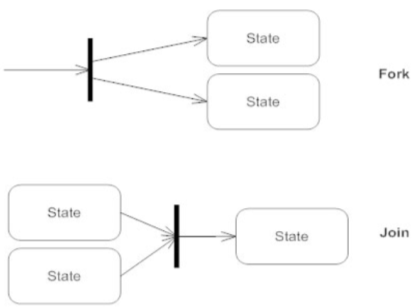
It is also possible to draw concurrent executions using fork and join nodes:
|
Fig 6: fork and join nodes
The fork node shown in the above diagram, represented as a solid vertical bar, shows the split of single transition into multiple concurrent transitions. Whereas the join node represents the multiple transitions merging into a single transition as shown in the above diagram.
Two forms of concurrency can occur in a system. They are − they are
System concurrency
Competitiveness is modelled on the level of the method here. The overall system is modelled as state machine aggregation, where each state machine operates simultaneously with others.
Concurrency within an object
Here, concurrent events can be generated by an entity. An entity may have states that are composed of sub-states, and in each of the sub-states there may be concurrent events.
Key takeaway :
● Concurrency is a property of a system in which the ability to perform two or more tasks at once will overlap multiple behaviours in time.
● concurrent events can be generated by an entity.
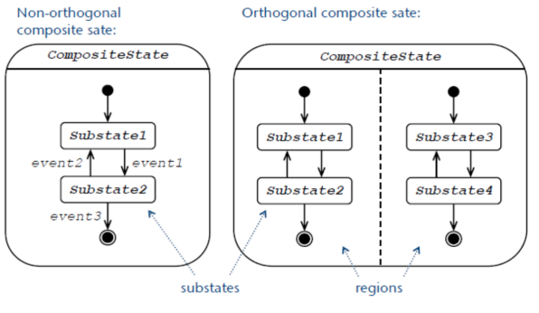
● Generally, composite state is defined as state that has substates (nested states)
● Substates could be sequential (disjoint) or concurrent (orthogonal)
● UML 2.4 defines composite state as the state which contains one or more regions.
(Note, that region is defined back as an orthogonal part of either a composite state or a state machine.)
● Simple composite state contains just one region.
● Orthogonal composite state has more than one region.
● Each region has a set of mutually exclusive disjoint subvertices and a set of transitions.
● A given state may only be decomposed in one of these two ways.
● Any state enclosed within a region of a composite state is called a substate of that composite state.
● It is called a direct substate when it is not contained by any other state; otherwise, it is referred to as an indirect substate.
● Each region of a composite state may have an initial pseudostate and a final state.
● A transition to the enclosing state represents a transition to the initial pseudostate in each region.
● A newly-created object takes its topmost default transitions, originating from the topmost initial pseudostates of each region.
● Composite state may have state name placed inside an attached name tab. The name tab is a rectangle, usually resting on the outside of the top side of a state.
● Composite states may have compartments. The compartments of the state are:
○ name compartment
○ internal activities compartment
○ internal transitions compartment
○ decomposition compartment
● The first three compartments are the same as for simple states.
● Decomposition compartment shows the composition structure of the state as a a nested diagram with regions, states, and transitions.
● For convenience and appearance, the text compartments may be shrunk horizontally within the graphic region.
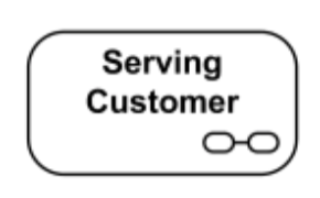
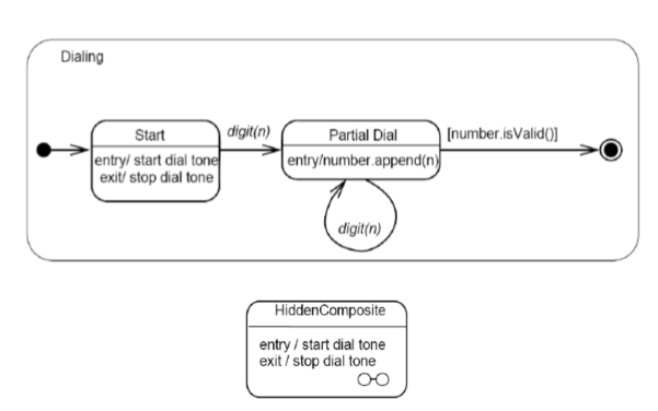
● In some cases, it is convenient to hide the decomposition of a composite state. For example, there may be a large number of states nested inside a composite state and they may simply not fit in the graphical space available for the diagram.
● In that case, the composite state may be represented by a simple state graphic with a special “composite” icon, usually in the lower right-hand corner.
● This icon, consisting of two horizontally placed and connected states, is an optional visual cue that the state has a decomposition that is not shown in this particular diagram.
● Instead, the contents of the composite state are shown in a separate diagram. “hiding” is a matter of graphical convenience and has no semantic significance in terms of access restrictions.
|
Fig 7: non-orthogonal and orthogonal composite state
|
Fig 8: Composite state Serving Customer with decomposition hidden.
Key takeaway :
● To model the complex system, a nested state diagram is used, as the standard state diagram is inadequate to explain the large and complex problem.
● The theory of advanced state modelling is the nested state diagram.
● So, this is all about the nested state diagram that helps to model the complex scheme that cannot be represented by the flat state diagram.
Features of advanced dynamic modelling are entry and exit behavior. As an alternative to linking them to transactions, behavior may be correlated with entering and leaving a state. When any change enters the state, an entry action is performed, and an exit action is performed when a state leaves. Without regard to what happens before a state becomes operational, this enables a state to be represented in terms of matched entry and exit behavior.
The state it executes within the state is not altered by an internal intervention. When their conditions are met and all operations in the current state is terminated, automatic transactions fire and modify the state.
The state it executes within the state is not altered by an internal intervention.
When their conditions are met and all operations in the current state is terminated, automatic transactions fire and modify the state.
Sending Events: An object together with an attribute may submit an event to another object. A race condition emerges when more than one object may accept events from a state. In this case, because it can affect the final state of the entity, the order of the events becomes essential.
Synchronization of concurrent activities : sometimes, the object may simultaneously perform two or more tasks at a time. The internal steps may not be coordinated, but all activities must be performed before the object may progress to the next level. Each diagram is triggered by any transformation into a state with sub diagrams.
Key takeaway :
● Features of advanced dynamic modelling are entry and exit behavior.
● As an alternative to linking them to transactions, behavior may be correlated with entering and leaving a state.
● When any change enters the state, an entry action is performed, and an exit action is performed when a state leaves.
● Without regard to what happens before a state becomes operational, this enables a state to be represented in terms of matched entry and exit behavior.
The dynamic model defines permissible sequences of modifications from the object model to the objects. The dynamic model states can be linked to the attribute classes
and relation values of an object, events can be interpreted as object model operations.
For the dynamic model, the object model principles of generalization, aggregation and inheritance also apply.
Generalization:
Each object substate limits the values an object may have, which is a special type of generalization, called restriction generalization. It is clear that the set of possible object values is partitioned both by generalization on classes and on states. When intrinsic distinctions between objects occur, they are modelled as distinct classes. They are modelled as distinct states of the same class when the variations are temporary.
Aggregation:
The aggregation of more than one substate is a composite state. There are two levels of aggregation, object aggregation (the composite state is an assembly of the individual states of the components) and object aggregation (attribute groups and relation values determine the composite state value).
Inheritance:
Hierarchies of events and states can be drawn. Events inherit their parent attributes (data values) and states inherit potential transformations. Its subclasses also inherit the dynamic model of a class.
Object model | Dynamic model |
Shows a static view of the system. | shows dynamic/behavioral view of the system |
It is represented graphically with class diagram , object diagram | it is represented graphically with stat diagram, collaboration and sequence diagram. |
Object model captures the structure of object and classes with their attributes, functions and relationships. | Dynamic model captures the behavioral changes in the state of object as per time and events
|
An object model explores the static structure of objects in a system and their relationships. | a dynamic model shows the time - dependent behavior of the system and the objects in it. |
It is built by i)identifying classes, attributes ii) identifying relationships among classes and objects iii) building class diagram or object diagram | it is built by i) identifying typical scenarios ii) identifying triggers and events iii) finding messages to share between objects iv) building state diagram or sequence diagram |
Key takeaway :
● The dynamic model defines permissible sequences of modifications from the object model to the objects.
● For the dynamic model, the object model principles of generalisation, aggregation and inheritance also apply.
Rumbaugh et al. have defined DFD as, “A data flow diagram is a graph which shows
the flow of data values from their sources in objects through processes that transform
them to their destinations on other objects.”
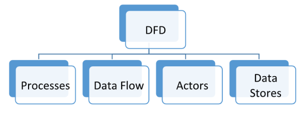
The major parts of the DFD can be shown as below
|
Fig 9: parts of DFD
Processes
These are the functional entities which are responsible for transforming data values,
from input to output data. We can assume whole system as a process which can be
further decomposed in smaller functional units where the lowest level functional unit can be a simple function from the system.
The graphical representation of the process can be shown below
|
Fig 10: process
Processes are represented as ellipses with the name of the process written inside the ellipse.
Data Flow
Flow of the data among the processes can be shown with the help of data flow. It can
be shown between process and actor as well as between process and data store. The
data flow carries the value of the data computed by the process at some point of time.
The graphical representation of the data flow cab shown below
|
It can be an arrow or directed arc labelled with the name of data it carries.
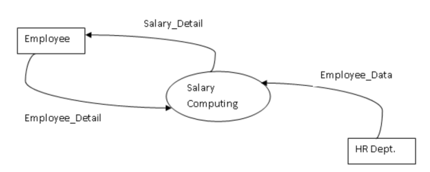
Actors are the objects which communicate with the system either for providing input to the system or to get the output from the system. It acts as sources of the data or the sinks of the data.
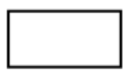
Actors are represented graphically as shown below
It can be represented as a rectangle with the name of the actor written inside the rectangle.
|
Fig 11: example of actor
Data Stores
It acts as a data repository. It does not perform any operation. It just stores and retrieves the data as when required.
It can be graphically represented as below
|
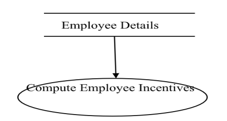
Following example shows the use of data store for computing employee incentives
|
Fig 12: example of data store
The DFD can be developed progressively in detail by using levels and layers. The DFD can have 0,1,2 ..levels depending upon the scope of the system.
Level 0 DFD: It is also called as Context Diagram. It gives a bird’s eye view of the whole system. It represents the whole system as a single high level process, in association with its external entities. The purpose of this diagram is to make the intended audience easily understand the idea about the system or project.
Level 1 DFD: It is one level deeper than the level 0 DFD. The context diagram is broken in to sub processes. The high level process represented in level 0 is divided into important functions which is shown as main functions of the level 1 DFD.
Level 2 DFD: to derive this DFD, the level 1 DFD is further divided into the sub functions. It goes one more level deeper to get the system functionalities in more details which is quite enough to define the system.
DFD can go beyond level 0 , 1 & 2 depending upon the complexity of the system but going beyond level 3 is not common, but creates unnecessary complexity in
understanding the system.
Key takeaway :
● “A data flow diagram is a graph which shows the flow of data values from their sources in objects through processes that transform them to their destinations on other objects.”
● Processes are represented as ellipses with the name of the process written inside the ellipse.
● Flow of the data among the processes can be shown with the help of data flow.
● Actors are the objects which communicate with the system either for providing input to the system or to get the output from the system.
● The DFD can be developed progressively by using levels and layers.
Relation of functional to object models
All four functional model components can be linked to the model of the entity.
Processes :
The functional model illustrates the procedures that have to be introduced in the object methods. The functional model processes show the objects that are connected by the function. The goal (client) of a process is always one in-or output. The parameters of the other inputs are (suppliers). Such client-supplier relationships create dependencies between the relevant groups in terms of implementation.
Actors :
In the object model, these are the objects.
Data stores :
There are objects in the object model or object attributes, too.
Data flows :
In the object model, these are values. Operations on or by things are represented by data flows to or from actors. Queries or changes are represented by data flows to or from data stores.
Relation to dynamic and functional model
The link between these two models is that when operations are finished, the dynamic model says, and the functional model tells how they are done and what arguments are required. There is, however, a distinction between stakeholder operations and data store operations. The dynamic model has to decide when it acts, since actors are active objects. Data stores are passive artefacts that only respond to changes and requests, so you don't have to decide when they function in the dynamic model.
Key takeaway :
● The functional model illustrates the procedures that have to be introduced in the object methods.
● The functional model processes show the objects that are connected by the function.
● The dynamic model has to decide when it acts, since actors are active objects.
References:
- “The Unified Modeling Language User Guide”, Grady Booch, Jeams Rambaugh, Ivar Jacotson, Addison Wesley.
2. “Object Oriented Analysis and Design”, Andrew High, TMG.
3. “Practical Object Oriented Design with UML”, Mark Priestley.
