Unit-4
Structural Modeling using UML
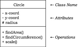
A class is represented by a rectangle that has three sections:
● The top part, which includes the class name,
● Class attributes in the middle segment
● The lower part of the class's activities
In the following ways, visibility of the attributes and operations can be interpreted
● Public: A member of the public is accessible from anywhere in the structure. It is prefixed with the symbol '+' in the class diagram.
● Private: Only from inside the class is a private member available. It is not possible to access it from outside the class. The sign '−' is prefixed by a private member.
● Protected: From within the class and from the subclasses inherited from this class, but not from outside, a covered member is visible. The sign '#' is prefixed by a protected member.
There is a class name written in italics in an abstract class.
Example: Let us consider the previously introduced Circle class. The Circle attributes are x-coord, y-coord, and radius. FindArea(), findCircumference(), and scale are the operations (). Let us assume that private data members are x-coord and y-coord, radius is a protected data member, and the functions of the member are public.
The following figure provides the class's diagrammatic representation.
|
Fig 1: example of class
Key takeaway:
● A member of the public is accessible from anywhere in the structure.
● Only from inside the class is a private member available.
● From within the class and from the subclasses inherited from this class, but not from outside, a covered member is visible.
The connection between things is relationships. The four relationship forms that can be expressed in UML are-
Dependency −
This is a semantic link between two things, such that a change in one thing brings about a change in the other. The former is the independent thing, while the dependent thing is the latter.
Association −
This is a structural relationship that expresses a community of interactions that have a similar structure and behavior.
Generalization −
This reflects a relationship of generalization / specialization in which subclasses inherit super-class structure and behavior.
Realization −
This is a semantic relationship between two or more classifiers in such a way that one classifier sets out a contract to be followed by the other classifiers.
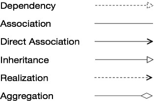
The notations are as follows for the various forms of relationships.
|
Fig 2: Notation used in relation
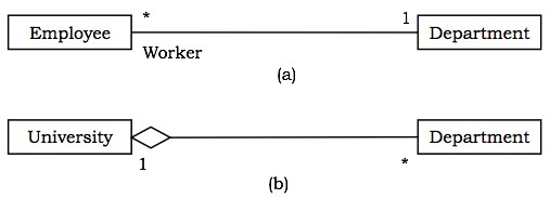
Usually, components in a relationship play particular roles in the relationship. A role name means the actions in a certain sense of an element participating.
|
Fig 3: different relationship between classes
Key takeaway:
● The connection between things is relationships.
● Dependency is a semantic link between two things, such that a change in one thing brings about a change in the other.
The four common mechanisms of UML are :
● Specifications
● Adornments
● Common Divisions
● Extensibility Mechanisms
Specifications
In UML, there is a textual statement denoting the syntax and semantics behind each graphical notation. The criteria are these. A semantic backplane that contains all the components of a device and the relationship between the various paths is given by the specifications.
Adornments
There is a special graphical notation of each variable in UML. In addition, there are notes to reflect the important aspects of an element, such as name, scope, visibility, etc.
Common Divisions
It is possible to separate object-oriented systems in several ways. The two common ways of separation are —
● Division of classes and objects − A class is an abstraction of a group of objects which are identical. The concrete instance that has real life in the framework is an entity.
● Division of Interface and Implementation − Rules for interaction are specified by an interface. The concrete implementation of the rules specified in the interface is the implementation.
Extensibility Mechanisms
UML is a language that is open-ended. The capabilities of UML can be expanded in a managed way to accommodate a system's requirements. The mechanisms for extensibility are −
● Stereotypes − It expands the UML vocabulary, from which it is possible to generate new building blocks from existing ones.
● Tagged Values − It expands the versatility of UML building blocks.
● Constraints − It extends the semantics of the construction blocks of UML.
Key takeaway :
● In UML, there is a textual statement denoting the syntax and semantics behind each graphical notation.
● It is possible to separate object-oriented systems in several ways.
● UML is a language that is open-ended.
A visual representation of a structure is a diagram. It usually consists of a group of elements in the form of a graph. UML comprises nine diagrams in total, namely −
● Class Diagram
● Object Diagram
● Use Case Diagram
● Sequence Diagram
● Collaboration Diagram
● State Chart Diagram
● Activity Diagram
● Component Diagram
● Deployment Diagram
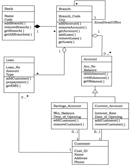
A class diagram models a system's static view. It reflects the types of objects that exist in the system and the relationships between them. A class consists of its objects, and it may also be inherited from other classes. A class diagram is used to visualise, define, record various system aspects and also create executable software code.
To offer an overview of the software system, it displays the attributes, classes, functions and relationships. It constitutes class names, attributes and functions in a separate compartment that assists in the creation of software. Because it is a set of classes, interfaces, partnerships, collaborations and constraints, it is called a structural diagram.
Objectives:
The primary objective of class diagrams is to create a static view of an application. It is the only diagram commonly used for construction, and with object-oriented languages it can be mapped. It is one of the most common diagrams for UML.
The object of the class diagrams given below is:
● It analyses a static view of an application and designs it.
● It defines a system's major responsibilities.
● It is a foundation for diagrams for components and deployment.
● It combines reverse and forward engineering.
|
Fig 4: example of class diagram
Advantages:
● For complicated structures, it may represent the object model.
● By giving an overview of how an application is designed before coding, it decreases the maintenance time.
● For better comprehension, it offers a general schematic of an application.
● By highlighting the desired code that is to be programmed, it represents a comprehensive graph.
● For the stakeholders and developers, it is beneficial.
Key takeaway:
● A class diagram models a system's static view.
● It reflects the types of objects that exist in the system and the relationships between them.
● A class diagram is used to visualize, define, record various system aspects and also create executable software code.
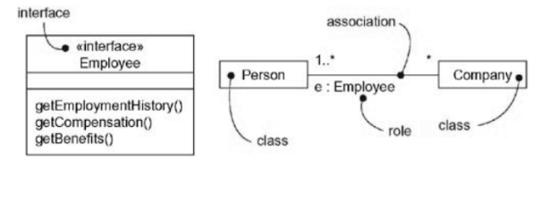
Interface is the set of a class or component methods. It specifies the collection of services that the class or part can provide.
Notation - An interface is generally drawn along with its name as a circle. The class or part that knows it almost always has an interface attached to it.
The notation of an interface is described in the following diagram.
|
Fig 5: interfaces
Key takeaway:
● Interface is the set of a class or component methods.
● It specifies the collection of services that the class or part can provide.
A type is a stereotype of a class that is used to specify an object domain, along with the operations (but not the methods) that relate to the object.
A class diagram like this one is helpful for modelling and abstraction static binding to its interface. By using the stereotype in an interaction diagram, you can model the dynamic binding of an abstraction to its interface, showing an entity moving from one position to another.
You'll want to use the given stereotype type if you want to formally model the semantics of an abstraction and its conformance to a particular interface.
Type is a class stereotype, and you use it to define an object domain, along with the operations (but not the methods) that refer to the objects of that type.
Roles
A role names the actions of an individual that is involved in a specific context. In other words, a role is the face shown to the world by an abstraction.
Consider, for instance, an example of the Individual class. Mother, Comforter, PayerOfBills, Employee, Client, Boss, Pilot, Singer, and so on will play the role depending on the context.
|
Fig 6: roles
It shows a face to the world when an entity plays a specific role, and consumers who communicate with it expect a certain behavior based on the role it plays at the time.
An example of a person in the position of manager will present a different set of
Properties then if the example plays the role of Mother.
You may define a function in the UML that the abstraction presents to another abstraction by decorating the name of the end of the association with a particular interface.
Key takeaway:
● The behavior of a person involved in a specific context is a role.
● A type is a stereotype of a class that is used to specify an object domain, along with the operations (but not the methods) that relate to the object.
An ordered set of elements is a kit. A package can include structural items in it, such as classes, modules, and other packages.
Notation − A package is defined by a tabbed folder, graphically. Generally, a package is drawn with only its name. It could, however, have additional information about the package's content.
The notation of an package is described in the following diagram
|
Fig 7: packages
Key takeaway:
● An ordered set of elements is a kit.
● A package can include structural items in it, such as classes, modules, and other packages.
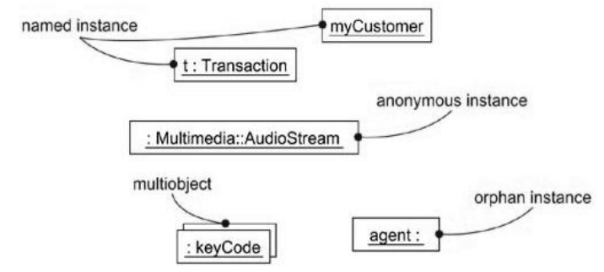
● An instance is a concrete manifestation of an abstraction to which it is possible to apply a series of operations and which has a state that stores the operations' results.
● Graphically, by underlining its name, an instance is made.
Abstraction and Instance
● While you can have instances of other items, such as modules, nodes, use cases, and associations, most instances you'll model with the UML will be class instances.
● An example is easily distinguishable from an abstract in the UML. You underscore its name to indicate an instance.
● To model these physical cases, we can use UML, but you can also model items that are not so concrete.
|
Fig 8: Named, Anonymous, Multiple, and Orphan Instances
Names
● Each instance must have a name that, within its context, differentiates it from other instances.
● An object usually resides within the scope of an operation, a part, or a node.
● A name is a string that's textual. Only the name is known as a simple name. Or it could be a name for a road.
Object Diagram
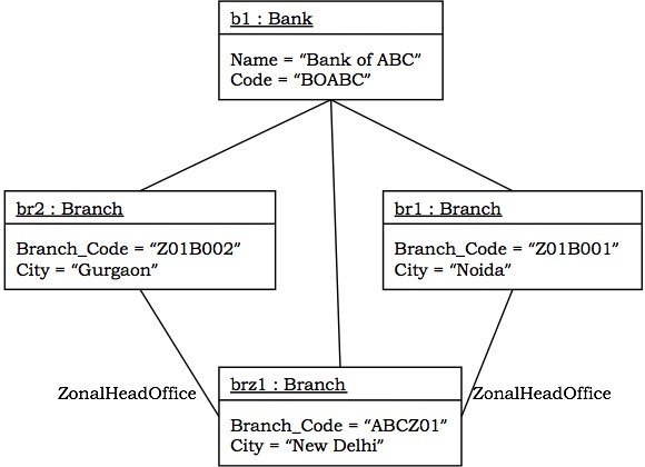
An object diagram at a point in time models a collection of objects and their connections. This illustrates the explanations of the items in a class diagram. The static component of an interaction diagram is the entity diagram.
To some degree, both the object and the class diagram are similar; the only distinction is that an abstract view of a structure is given by the class diagram. It helps to imagine a system's basic features.
Purpose:
The diagram of the object holds the same function as the diagram of a class. The class diagram offers an abstract view of classes and their relationships, while the object diagram at a specific point of time represents a case.
In reality, the object diagram is identical to the concrete (actual) actions of the device. The primary goal is to present a static view of a system.
The purposes listed below are as follows:
● It is used for forward and reverse engineering performance.
● It is used to practically understand the behaviour of objects and their relationships.
● In order to get a static view of a system, it is used.
● To represent an example of a method, it is used
|
Fig 9: object diagram
Application :
The following are the application fields where you can use the object diagrams.
● To build a machine prototype.
● To model complicated structures of data.
● From a realistic viewpoint to view the device.
Key takeaway :
● An object diagram at a point in time models a collection of objects and their connections.
● In reality, the object diagram is identical to the actual actions of the device.
● An instance is a concrete manifestation of an abstraction to which it is possible to apply a series of operations and which has a state that stores the operations' results.
References:
- “The Unified Modeling Language User Guide”, Grady Booch, Jeams Rambaugh, Ivar Jacotson, Addison Wesley.
- “Object Oriented Analysis and Design”, Andrew High, TMG.
- “Object Oriented Analysis and Design”, Kahate, TMH.
