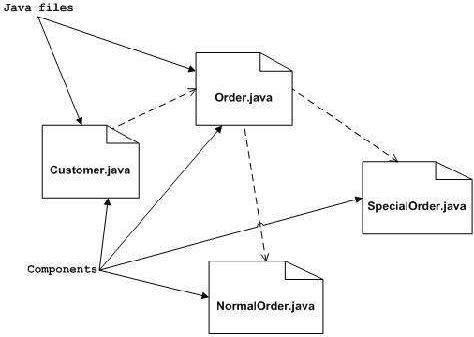
A component is a replaceable physical component of a system that complies with a collection of interfaces and provides them for realization. To model the physical items that might reside on a node, such as executables, libraries, tables, files and documents, we use components.
The physical packaging of otherwise logical components, such as classes, interfaces and partnerships, is usually represented by a component. To imagine, specify, and record our decisions about our domain's vocabulary and the systemic and behavioral way those things work together, we do logical modelling.
To build the executable framework, we do physical modelling. All examples of components are object libraries, executables, COM+ components and Enterprise Java Beans.
Names
|
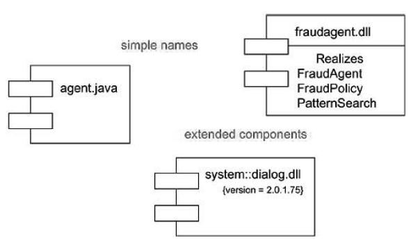
Fig 1: simple and extended components
Names
Every element must have a name that differentiates it from other elements. A name is a string that's textual. The name alone is regarded as a simple name; the name of the route is the name of the component prefixed with the name of the package where that component resides. Usually, a part is drawn showing only its name. Just as with groups, to reveal their information, you can draw components adorned with tagged values or with additional compartments.
Components and Classes
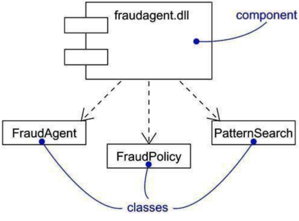
Components are like classes in several ways: both have names; both may recognize a set of interfaces; both may engage in relationships of dependence, generalization, and association; both may be nested; both may have Instances; both may be representatives of interactions.
There are some essential distinctions between components and classes, however.
● Logical abstractions are represented by classes; components represent physical objects residing in the universe of bits. In short, on nodes, components may live, groups may not.
● Components represent, and are at a separate level of abstraction, the actual packaging of otherwise logical components.
● Groups can directly have attributes and operations. Components usually only have operations that can only be accessed via their interfaces.
|
Fig 2: components and classes
Key takeaway:
● A component is a replaceable physical component of a system that complies with a collection of interfaces and provides them for realization.
● Every element must have a name that differentiates it from other elements.
● The physical packaging of otherwise logical components, such as classes, interfaces and partnerships, is usually represented by a component.
Deployment reflects the physical nodes of the hardware-forming device. In support of this view, the UML deployment diagram is used.
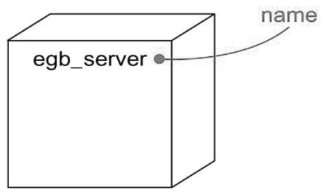
A node is a physical element that resides and represents a computational resource at runtime, typically with at least some memory and, often, processing capability. A node is, graphically, rendered as a cube.
We have to understand both its conceptual and physical dimensions when we architect a software-intensive device. You'll find stuff like classes, interfaces, partnerships, interactions and state machines on the logical side. You'll find the modules and nodes on the physical side.
Name
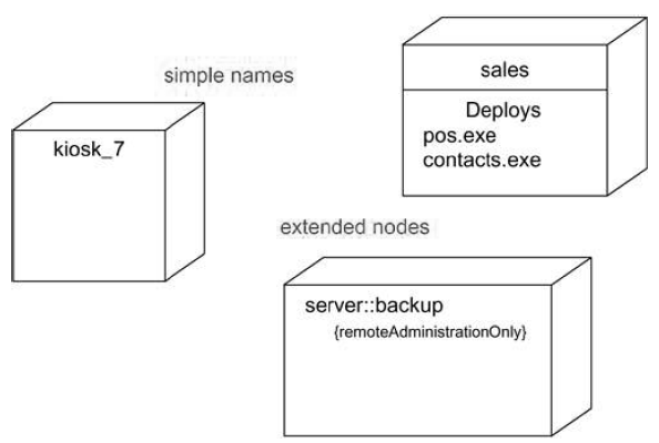
Each node must have a name which differentiates it from other nodes. A name is a string that's textual. The name alone is regarded as a simple name; the name of the route is the name of the node prefixed with the name of the package where that node resides. Usually, a node is drawn displaying only its name . Just as with groups, to reveal their data, you can draw nodes adorned with tagged values or with additional compartments.
|
Fig 3: simple and extended names
Nodes and Components
Nodes are like modules in several ways: both have names, both can engage in relationships of dependence, generalization and association. Both may be nested, both may have cases, both may be contact participants.
There are essential distinctions, however, between nodes and components:
● Components are things that participate in a system's execution. Nodes are component-executing stuff.
● Components represent the actual packaging of logical components, and nodes represent the physical component implementation.
|
Fig 4: node
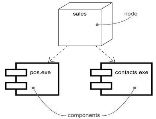
A collection of items or components which are assigned as a group to a node is called a distribution unit.
|
Fig 5: components
Connections
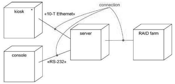
An association is the most common form of relationship we'll use between nodes. In this context, an association is a physical link between nodes, such as a serial line, an Ethernet connection, or a shared bus. To model indirect links, such as a satellite link between distant processors, we can also use associations.
|
Fig 6: connections
Key takeaway:
● Deployment reflects the physical nodes of the hardware-forming device.
● Each node must have a name which differentiates it from other nodes.
● A name is a string that's textual.
● An association is the most common form of relationship we'll use between nodes.
● A Collaboration is a set of named objects and actors with relations that bind them. In performing any task, they collaborate.
● For a given set of purposes, a collaboration describes a set of participants and relationships that are meaningful.
● In Object-Oriented systems, a partnership between objects working together offers evolving desirable functionalities.
● Each object (responsibility) supports the evolving features in part.
● By working together, artefacts may generate (usable) high-level functionalities.
● Objects cooperate to work together by interacting (passing messages) with each other.
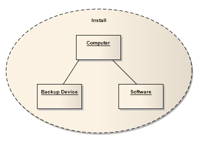
A Collaboration describes a set of roles and their connectors that cooperate. These are used in a Composite Structure diagram to collectively demonstrate a particular functionality. Only the roles and attributes needed to perform a particular task or function should be defined by a collaboration. While a behavior and its functions which include several tangential features and characteristics in operation, isolating the primary roles and their specifications simplifies and clarifies the behavior and allows for reuse. In order to apply to different contexts, a partnership also introduces a pattern.
|
Fig 6: example of install collaboration
Key takeaway:
● A Collaboration is a set of named objects and actors with relations that bind them.
● For a given set of purposes, a collaboration describes a set of participants and relationships that are meaningful.
● A Collaboration describes a set of roles and their connectors that cooperate.
In order to minimize the time for production and improve efficiency, a development team prefers to reuse the existing solutions.
The reuse of an existing solution requires the reuse of the current code, a part, a test case, or a principle applied in similar projects.
Standards are structures and patterns that are used to render reusable software components.
Frameworks
Defines features common to similar applications that belong to a specific domain. Boost reusability and decrease the production time of applications.
An example of a framework that allows you to create Graphical User Interfaces (GUI) that have common features, such as command buttons, is Microsoft Foundation Classes (MFC) provided with Microsoft VC++.
A structure has the characteristics of :
● Represents a class or library set that allows you to perform a specific function without the code being created from scratch.
● Contains abstract and concrete classes that comply with predefined requirements by making interfaces.
● This includes groups that can be expanded by subclassification.
● Defines the abstract methods which receive messages from the predefined classes in the derived class.
Pattern
It is a set of principles and guidelines that provide a given problem with a standard solution.
It helps you to build solutions that can be replicated without requiring adjustments to the current system to satisfy new requirements.
It is helpful in making contact between components of software easier. It is helpful in making the design reusable, addressing a problem in the most successful way, and assigning classroom responsibilities.
In general, they are grouped into the following categories:
● General Responsibility Assignment Software Patterns (GRASP)
● Gang of Four (GoF) patterns
GRASP
GRASP is a collection of patterns, such as creating and destroying an object, that provide the principles of assigning responsibilities to objects.
The following trends consist of :
● Expert: Provides instructions for assigning liability to a class containing the knowledge applicable to it.
● Creator: Provides instructions for assigning liability to a specific class's new object.
● Controller: Offers instructions for device event management.
The professional model offers guidelines for assigning liability to a class containing the relevant data.
A class is accountable for creating objects, according to the creator pattern, if any of the following conditions are true:
● Another class requires a class.
● The instances of another class are registered by a class.
● The objects of another class are being used by a class.
● To initialize the objects of another class, a class provides details.
You delegate responsibility for managing a system event to a class that meets one or more of the following requirements, according to the controller pattern:
● Represents the overall system.
● Represents a case handler for use.
GoF patterns
They are based on the concept of open-close, suggesting that the design should be open to extension and close to alteration.
You have the following characteristics: -
● It helps you to reuse current solutions for common design issues.
● Establishes standard terms for concerns and their solutions to promote comprehension.
Creative systemic behavior is broadly classified into three types:
● Creational
● Structural
● Behavioral
Key takeaway:
● Standards are structures and patterns that are used to render reusable software components.
● Defines features common to similar applications that belong to a specific domain. Boost reusability and decrease the production time of applications.
● GRASP is a collection of patterns, such as creating and destroying an object, that provide the principles of assigning responsibilities to objects.
● They are based on the concept of open-close, suggesting that the design should be open to extension and close to alteration.
It is important to break down the framework into manageable subsystems when modelling large object-oriented systems. For modelling large systems into smaller subsystems, UML component diagrams are used that can be easily handled.
A component is a replaceable and executable component of a scheme whose specifics of implementation are secret. The set of interfaces which a component realises or implements is given by a component. Components often require interfaces for a role to be carried out.
To represent various components of a system, UML Component diagrams are used.
Component diagrams of UML have important significance. The component diagram varies from other diagrams in different ways. While other diagrams are used to represent the system, a system's operation or a system's architecture. Component diagrams are used to explain the operation and action of different device components.
This reflects how each variable functions during a system execution.
These are the static diagrams of the unified modelling language. A component diagram is used for any period of time to represent the configuration and arrangement of components.
To model the subsystems, component diagrams are used. These subsystems collectively represent the entire working view of any system.
The entire system cannot be visualized by a single component, but the set of multiple components can.
Component diagrams are used, therefore, for,
● To reflect at runtime the components of any device.
● It helps during a system's testing.
● This visualizes the relationship between different elements.
|
Fig 7: component diagram of order management system
Deployment Diagram
The object of the diagram is defined by the term deployment itself. In order to describe the hardware components where the software components are deployed, deployment diagrams are used. Diagrams of components and deployment diagrams are closely related.
System engineers use deployment diagrams. Most UML diagrams are used to manage logical elements, but deployment diagrams are structured to concentrate on a system's hardware topology.
The purpose of deployment diagrams can be defined as −
● Visualize a system's hardware topology.
● Describe the components of hardware used to deploy components of software.
● Describe the nodes of runtime processing.
For device engineers, deployment diagrams are useful. As it regulates the following parameters, an effective deployment diagram is very important -
● Performance
● Scalability
● Maintainability
● Portability
The following objects should be defined before drawing a deployment diagram.
● Nodes
● Relationships among nodes
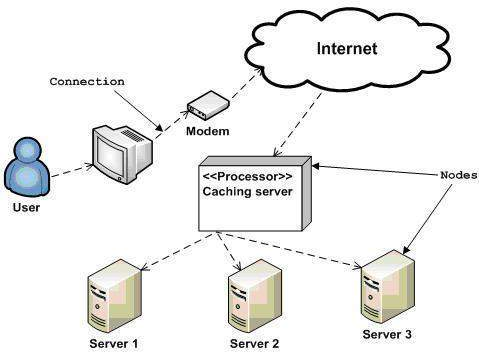
A sample implementation diagram is below to provide an understanding of the order management system deployment view. Here, we showed the nodes as nodes -
● Monitor
● Modem
● Caching server
● Server
It is known that the application is a web-based application that is deployed using server 1, server 2, and server 3 in a clustered environment. The user, using the Internet, connects to the programmer. The power flows to the clustered environment from the caching server.
Considering all the points listed above, the following deployment diagram has been drawn.
|
Fig 8: deployment diagram of an order management system
Key takeaway:
● In terms of design and behavior, component diagrams are distinct. To model the physical aspects of a scheme, part diagrams are used.
● To visualize the organization and relationships between components in a system, component diagrams are used.
● To render executable systems, these diagrams are also used.
● The object of the diagram is defined by the term deployment itself.
● In order to describe the hardware components where the software components are deployed, deployment diagrams are used.
● Diagrams of components and deployment diagrams are closely related.
References:
- “Object Oriented Modeling and Design”, Rambaugh, Premerlani, Eddy, Lorenson, PHI.
- “The Unified Modeling Language User Guide”, Grady Booch, Jeams Rambaugh, Ivar Jacotson, Addison Wesley.
- “Object Oriented Analysis and Design”, Kahate, TMH.
