Unit-1
Introduction and Database Modelling using ER Model
What is Data?
Data is a collection of a distinct small unit of information. It can be used in a variety of forms like text, numbers, media, bytes, etc. it can be stored in pieces of paper or electronic memory, etc.
Word 'Data' is originated from the word 'datum' that means 'single piece of information.' It is plural of the word datum.
In computing, Data is information that can be translated into a form for efficient movement and processing. Data is interchangeable.
What is Database?
A database is an organized collection of data, so that it can be easily accessed and managed.
You can organize data into tables, rows, columns, and index it to make it easier to find relevant information.
Database handlers create a database in such a way that only one set of software program provides access of data to all the users.
The main purpose of the database is to operate a large amount of information by storing, retrieving, and managing data.
There are many dynamic websites on the World Wide Web nowadays which are handled through databases. For example, a model that checks the availability of rooms in a hotel. It is an example of a dynamic website that uses a database.
There are many databases available like MySQL, Sybase, Oracle, MongoDB, Informix, PostgreSQL, SQL Server, etc.
Modern databases are managed by the database management system (DBMS).
SQL or Structured Query Language is used to operate on the data stored in a database. SQL depends on relational algebra and tuple relational calculus.
A cylindrical structure is used to display the image of a database.

Fig 1- Image of a database
Evolution of Databases
The database has completed more than 50 years of journey of its evolution from flat-file system to relational and objects relational systems. It has gone through several generations.
The Evolution
File-Based
1968 was the year when File-Based database were introduced. In file-based databases, data was maintained in a flat file. Though files have many advantages, there are several limitations.
One of the major advantages is that the file system has various access methods, e.g., sequential, indexed, and random.
It requires extensive programming in a third-generation language such as COBOL, BASIC.
Hierarchical Data Model
1968-1980 was the era of the Hierarchical Database. Prominent hierarchical database model was IBM's first DBMS. It was called IMS (Information Management System).
In this model, files are related in a parent/child manner.
Below diagram represents Hierarchical Data Model. Small circle represents objects.
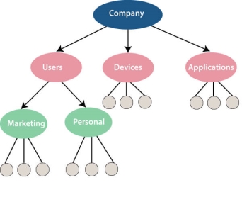
Fig 2 - Hierarchical Data Model
Like file system, this model also had some limitations like complex implementation, lack structural independence, can't easily handle a many-many relationship, etc.
Network data model
Charles Bachman developed the first DBMS at Honeywell called Integrated Data Store (IDS). It was developed in the early 1960s, but it was standardized in 1971 by the CODASYL group (Conference on Data Systems Languages).
In this model, files are related as owners and members, like to the common network model.
Network data model identified the following components:
This model also had some limitations like system complexity and difficult to design and maintain.
Relational Database
1970 - Present: It is the era of Relational Database and Database Management. In 1970, the relational model was proposed by E.F. Codd.
Relational database model has two main terminologies called instance and schema.
The instance is a table with rows or columns
Schema specifies the structure like name of the relation, type of each column and name.
This model uses some mathematical concept like set theory and predicate logic.
The first internet database application had been created in 1995.
During the era of the relational database, many more models had introduced like object-oriented model, object-relational model, etc.
Cloud database
Cloud database facilitates you to store, manage, and retrieve their structured, unstructured data via a cloud platform. This data is accessible over the Internet. Cloud databases are also called a database as service (DBaaS) because they are offered as a managed service.
Some best cloud options are:
Advantages of cloud database
Lower costs
Generally, company provider does not have to invest in databases. It can maintain and support one or more data centers.
Automated
Cloud databases are enriched with a variety of automated processes such as recovery, failover, and auto-scaling.
Increased accessibility
You can access your cloud-based database from any location, anytime. All you need is just an internet connection.
NoSQL Database
A NoSQL database is an approach to design such databases that can accommodate a wide variety of data models. NoSQL stands for "not only SQL." It is an alternative to traditional relational databases in which data is placed in tables, and data schema is perfectly designed before the database is built.
NoSQL databases are useful for a large set of distributed data.
Some examples of NoSQL database system with their category are:
Advantage of NoSQL
High Scalability
NoSQL can handle an extensive amount of data because of scalability. If the data grows, NoSQL database scale it to handle that data in an efficient manner.
High Availability
NoSQL supports auto replication. Auto replication makes it highly available because, in case of any failure, data replicates itself to the previous consistent state.
Disadvantage of NoSQL
Open source
NoSQL is an open-source database, so there is no reliable standard for NoSQL yet.
Management challenge
Data management in NoSQL is much more complicated than relational databases. It is very challenging to install and even more hectic to manage daily.
GUI is not available
GUI tools for NoSQL database are not easily available in the market.
Backup
Backup is a great weak point for NoSQL databases. Some databases, like MongoDB, have no powerful approaches for data backup.
The Object-Oriented Databases
The object-oriented databases contain data in the form of object and classes. Objects are the real-world entity, and types are the collection of objects. An object-oriented database is a combination of relational model features with objects-oriented principles. It is an alternative implementation to that of the relational model.
Object-oriented databases hold the rules of object-oriented programming. An object-oriented database management system is a hybrid application.
The object-oriented database model contains the following properties.
Object-oriented programming properties
Relational database properties
Graph Databases
A graph database is a NoSQL database. It is a graphical representation of data. It contains nodes and edges. A node represents an entity, and each edge represents a relationship between two edges. Every node in a graph database represents a unique identifier.
Graph databases are beneficial for searching the relationship between data because they highlight the relationship between relevant data.

Fig 3 - Graph databases
Graph databases are very useful when the database contains a complex relationship and dynamic schema.
It is mostly used in supply chain management, identifying the source of IP telephony.
DBMS (Data Base Management System)
Database management System is software which is used to store and retrieve the database. For example, Oracle, MySQL, etc.; these are some popular DBMS tools.
Advantage of DBMS
Controls redundancy
It stores all the data in a single database file, so it can control data redundancy.
Data sharing
An authorized user can share the data among multiple users.
Backup
It provides Backup and recovery subsystem. This recovery system creates automatic data from system failure and restores data if required.
Multiple user interfaces
It provides a different type of user interfaces like GUI, application interfaces.
Disadvantage of DBMS
Size
It occupies large disk space and large memory to run efficiently.
Cost
DBMS requires a high-speed data processor and larger memory to run DBMS software, so it is costly.
Complexity
DBMS creates additional complexity and requirements.
RDBMS (Relational Database Management System)
The word RDBMS is termed as 'Relational Database Management System.' It is represented as a table that contains rows and column.
RDBMS is based on the Relational model; it was introduced by E. F. Codd.
A relational database contains the following components:
An RDBMS is a tabular DBMS that maintains the security, integrity, accuracy, and consistency of the data.
Key takeaway
A database is an organized collection of data, so that it can be easily accessed and managed.
You can organize data into tables, rows, columns, and index it to make it easier to find relevant information.
Database handlers create a database in such a way that only one set of software program provides access of data to all the users.
The main purpose of the database is to operate a large amount of information by storing, retrieving, and managing data.
There are many dynamic websites on the World Wide Web nowadays which are handled through databases. For example, a model that checks the availability of rooms in a hotel. It is an example of a dynamic website that uses a database.
There are many databases available like MySQL, Sybase, Oracle, MongoDB, Informix, PostgreSQL, SQL Server, etc.
Modern databases are managed by the database management system (DBMS).
SQL or Structured Query Language is used to operate on the data stored in a database. SQL depends on relational algebra and tuple relational calculus.
Types of DBMS Architecture
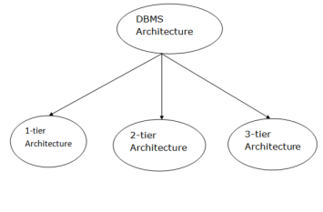
Fig 4 - DBMS Architecture
Database architecture can be seen as a single tier or multi-tier. But logically, database architecture is of two types like: 2-tier architecture and 3-tier architecture.
1-Tier Architecture
2-Tier Architecture
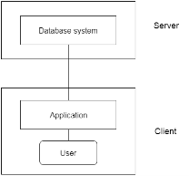
Fig 5: 2-tier Architecture
3-Tier Architecture
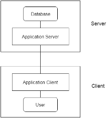
Fig 6: 3-tier Architecture
Key takeaway
Database Users
Database users are the one who really use and take the benefits of database. There will be different types of users depending on their need and way of accessing the database.
Database Administrators
The life cycle of database starts from designing, implementing to administration of it. A database for any kind of requirement needs to be designed perfectly so that it should work without any issues. Once all the design is complete, it needs to be installed. Once this step is complete, users start using the database. The database grows as the data grows in the database. When the database becomes huge, its performance comes down. Also accessing the data from the database becomes challenge. There will be unused memory in database, making the memory inevitably huge. These administration and maintenance of database is taken care by database Administrator – DBA.
A DBA has many responsibilities. A good performing database is in the hands of DBA.
In order to perform his entire task, he should have very good command over DBMS.
Types of DBA
There are different kinds of DBA depending on the responsibility that he owns.
Key takeaway
Database Users
Database users are the one who really use and take the benefits of database. There will be different types of users depending on their need and way of accessing the database.
Database Administrators
The life cycle of database starts from designing, implementing to administration of it. A database for any kind of requirement needs to be designed perfectly so that it should work without any issues. Once all the design is complete, it needs to be installed. Once this step is complete, users start using the database. The database grows as the data grows in the database. When the database becomes huge, its performance comes down. Also accessing the data from the database becomes challenge. There will be unused memory in database, making the memory inevitably huge. These administration and maintenance of database is taken care by database Administrator – DBA.
A DBA has many responsibilities. A good performing database is in the hands of DBA.
Data models define how the logical structure of a database is modeled. Data Models are fundamental entities to introduce abstraction in a DBMS. Data models define how data is connected to each other and how they are processed and stored inside the system.
The very first data model could be flat data-models, where all the data used are to be kept in the same plane. Earlier data models were not so scientific, hence they were prone to introduce lots of duplication and update anomalies.
Entity-Relationship Model
Entity-Relationship (ER) Model is based on the notion of real-world entities and relationships among them. While formulating real-world scenario into the database model, the ER Model creates entity set, relationship set, general attributes and constraints.
ER Model is best used for the conceptual design of a database.
ER Model is based on −
These concepts are explained below.

Fig 7 – ER Model
Mapping cardinalities −
Relational Model
The most popular data model in DBMS is the Relational Model. It is more scientific a model than others. This model is based on first-order predicate logic and defines a table as an n-ary relation.
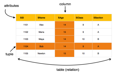
Fig 8 – Relational model
The main highlights of this model are −
Key takeaway
Data models define how the logical structure of a database is modeled. Data Models are fundamental entities to introduce abstraction in a DBMS. Data models define how data is connected to each other and how they are processed and stored inside the system.
The very first data model could be flat data-models, where all the data used are to be kept in the same plane. Earlier data models were not so scientific, hence they were prone to introduce lots of duplication and update anomalies.
Database management system is software that is used to manage the database.
What is Database?
The database is a collection of inter-related data which is used to retrieve, insert and delete the data efficiently. It is also used to organize the data in the form of a table, schema, views, and reports, etc.
For example: The college Database organizes the data about the admin, staff, students and faculty etc.
Using the database, you can easily retrieve, insert, and delete the information.
Database Management System
DBMS allows users the following tasks:
Characteristics of DBMS
Advantages of DBMS
Disadvantages of DBMS
Key takeaway
Database management system is software that is used to manage the database.
What is Database?
The database is a collection of inter-related data which is used to retrieve, insert and delete the data efficiently. It is also used to organize the data in the form of a table, schema, views, and reports, etc.
For example: The college Database organizes the data about the admin, staff, students and faculty etc.
Using the database, you can easily retrieve, insert, and delete the information.
Types of Database Language
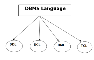
Fig 9 – DBMS Language
1. Data Definition Language
Here are some tasks that come under DDL:
These commands are used to update the database schema that's why they come under Data definition language.
2. Data Manipulation Language
DML stands for Data Manipulation Language. It is used for accessing and manipulating data in a database. It handles user requests.
Here are some tasks that come under DML:
3. Data Control Language
(But in Oracle database, the execution of data control language does not have the feature of rolling back.)
Here are some tasks that come under DCL:
There are the following operations which have the authorization of Revoke:
CONNECT, INSERT, USAGE, EXECUTE, DELETE, UPDATE and SELECT.
4. Transaction Control Language
TCL is used to run the changes made by the DML statement. TCL can be grouped into a logical transaction.
Here are some tasks that come under TCL:
Key takeaway
View of data in DBMS narrate how the data is visualized at each level of data abstraction? Data abstraction allow developers to keep complex data structures away from the users. The developers achieve this by hiding the complex data structures through levels of abstraction.
There is one more feature that should be kept in mind i.e. the data independence. While changing the data schema at one level of the database must not modify the data schema at the next level. In this section, we will discuss the view of data in DBMS with data abstraction, data independence, data schema in detail.
Data abstraction is hiding the complex data structure in order to simplify the user’s interface of the system. It is done because many of the users interacting with the database system are not that much computer trained to understand the complex data structures of the database system.
To achieve data abstraction, we will discuss a Three-Schema architecture which abstracts the database at three levels discussed below:
Three-Schema Architecture:The main objective of this architecture is to have an effective separation between the user interface and the physical database. So, the user never has to be concerned regarding the internal storage of the database and it has a simplified interaction with the database system.
The three-schema architecture defines the view of data at three levels:
1. Physical Level/ Internal Level
The physical or the internal level schema describes how the data is stored in the hardware. It also describes how the data can be accessed. The physical level shows the data abstraction at the lowest level and it has complex data structures. Only the database administrator operates at this level.
2. Logical Level/ Conceptual Level
It is a level above the physical level. Here, the data is stored in the form of the entity set, entities, their data types, the relationship among the entity sets, user operations performed to retrieve or modify the data and certain constraints on the data. Well adding constraints to the view of data adds the security. As users are restricted to access some particular parts of the database.
It is the developer and database administrator who operates at the logical or the conceptual level.
3. View Level/ User level/ External level
It is the highest level of data abstraction and exhibits only a part of the whole database. It exhibits the data in which the user is interested. The view level can describe many views of the same data. Here, the user retrieves the information using different application from the database.
The figure below describes the three-schema architecture of the database:
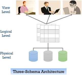
Fig 10 - Three-schema architecture
In the figure above you can clearly distinguish between the three levels of abstraction. To understand it more clearly let us take an example:
We have to create a database of a college. Now, what entity sets would be involved? Student, Lecturer, Department, Course and so on…
Now, the entity sets Student, Lecturer, Department, Course will be stored in the storage as the consecutive blocks of the memory location. This is the physical or internal level and is hidden from the programmers but the database administrator is it aware of it.
At the logical level, the programmers define the entity sets and relationship among these entity sets using a programming language like SQL. So, the programmers work at the logical level and even the database administrator also operates at this level.
At the view level, the users have the set of applications which they use to retrieve the data they are interested in.
Data Independence
Data independence defines the extent to which the data schema can be changed at one level without modifying the data schema at the next level. Data independence can be classified as shown below:
Logical Data Independence:Logical data independence describes the degree up to which the logical or conceptual schema can be changed without modifying the external schema. Now, a question arises what is the need to change the data schema at a logical or conceptual level?
Well, the changes to data schema at the logical level are made either to enlarge or reduce the database by adding or deleting more entities, entity sets, or changing the constraints on data.
Physical Data Independence:Physical data independence defines the extent up to which the data schema can be changed at the physical or internal level without modifying the data schema at logical and view level.
Well, the physical schema is changed if we add additional storage to the system or we reorganize some files to enhance the retrieval speed of the records.
Instances and Schemas
What is an instance?We can define an instance as the information stored in the database at a particular point of time. Let us discuss it with the help of an example.
As we discussed above the database comprises of several entity sets and the relationship between them. Now, the data in the database keeps on changing with time. As we keep inserting or deleting the data to and from the database.
Now, at a particular time if we retrieve any information from the database then that corresponds to an instance.
What is schema?Whenever we talk about the database the developers have to deal with the definition of database and the data in the database.
The definition of a database comprises of the description of what data it would contain what would be the relationship between the data. This definition is the database schema.
Key Takeaway
Data Model is the modelling of the data description, data semantics, and consistency constraints of the data. It provides the conceptual tools for describing the design of a database at each level of data abstraction. Therefore, there are following four data models used for understanding the structure of the database:
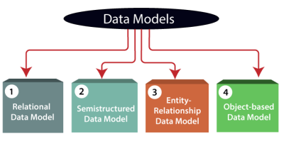
Fig 11 – Data Models
1) Relational Data Model: This type of model designs the data in the form of rows and columns within a table. Thus, a relational model uses tables for representing data and in-between relationships. Tables are also called relations. This model was initially described by Edgar F. Codd, in 1969. The relational data model is the widely used model which is primarily used by commercial data processing applications.
2) Entity-Relationship Data Model: An ER model is the logical representation of data as objects and relationships among them. These objects are known as entities, and relationship is an association among these entities. This model was designed by Peter Chen and published in 1976 papers. It was widely used in database designing. A set of attributes describe the entities. For example, student_name, student_id describes the 'student' entity. A set of the same type of entities is known as an 'Entity set', and the set of the same type of relationships is known as 'relationship set'.
3) Object-based Data Model: An extension of the ER model with notions of functions, encapsulation, and object identity, as well. This model supports a rich type system that includes structured and collection types. Thus, in 1980s, various database systems following the object-oriented approach were developed. Here, the objects are nothing but the data carrying its properties.
4) Semistructured Data Model: This type of data model is different from the other three data models (explained above). The semistructured data model allows the data specifications at places where the individual data items of the same type may have different attributes sets. The Extensible Markup Language, also known as XML, is widely used for representing the semistructured data. Although XML was initially designed for including the markup information to the text document, it gains importance because of its application in the exchange of data.
Key takeaway
Data Model is the modelling of the data description, data semantics, and consistency constraints of the data. It provides the conceptual tools for describing the design of a database at each level of data abstraction.
For example, suppose we design a school database. In this database, the student will be an entity with attributes like address, name, id, age, etc. The address can be another entity with attributes like city, street name, pin code, etc and there will be a relationship between them.
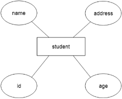
Fig 12 - Example
Component of ER Diagram
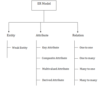
Fig 13 – Components of ER Diagram
1. Entity:
An entity may be any object, class, person or place. In the ER diagram, an entity can be represented as rectangles.
Consider an organization as an example- manager, product, employee, department etc. can be taken as an entity.

a. Weak Entity
An entity that depends on another entity called a weak entity. The weak entity doesn't contain any key attribute of its own. The weak entity is represented by a double rectangle.

2. Attribute
The attribute is used to describe the property of an entity. Eclipse is used to represent an attribute.
For example, id, age, contact number, name, etc. can be attributes of a student.
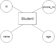
a. Key Attribute
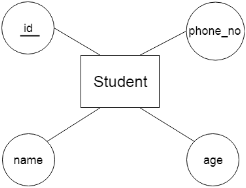
The key attribute is used to represent the main characteristics of an entity. It represents a primary key. The key attribute is represented by an ellipse with the text underlined.
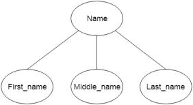
b. Composite Attribute
An attribute that composed of many other attributes is known as a composite attribute. The composite attribute is represented by an ellipse, and those ellipses are connected with an ellipse.
c. Multivalued Attribute
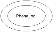
An attribute can have more than one value. These attributes are known as a multivalued attribute. The double oval is used to represent multivalued attribute.
For example, a student can have more than one phone number.
d. Derived Attribute
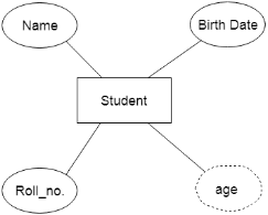
An attribute that can be derived from other attribute is known as a derived attribute. It can be represented by a dashed ellipse.
For example,A person's age changes over time and can be derived from another attribute like Date of birth.
3. Relationship
A relationship is used to describe the relation between entities. Diamond or rhombus is used to represent the relationship.

Types of relationship are as follows:
a. One-to-One Relationship
When only one instance of an entity is associated with the relationship, then it is known as one to one relationship.
For example,A female can marry to one male, and a male can marry to one female.

b. One-to-many relationship
When only one instance of the entity on the left, and more than one instance of an entity on the right associates with the relationship then this is known as a one-to-many relationship.
For example, Scientist can invent many inventions, but the invention is done by the only specific scientist.

c. Many-to-one relationship
When more than one instance of the entity on the left, and only one instance of an entity on the right associates with the relationship then it is known as a many-to-one relationship.
For example, Student enrolls for only one course, but a course can have many students.

d. Many-to-many relationship
When more than one instance of the entity on the left, and more than one instance of an entity on the right associates with the relationship then it is known as a many-to-many relationship.
For example, Employee can assign by many projects and project can have many employees.

Key takeaway
Entity in DBMS can be a real-world object with an existence, For example, in a College database, the entities can be Professor, Students, Courses, etc.
Entities has attributes, which can be considered as properties describing it, for example, for Professor entity, the attributes are Professor_Name, Professor_Address, Professor_Salary, etc. The attribute value gets stored in the database.
Example of Entity in DBMS
Let us see an example −
<Professor>
Professor_ID | Professor_Name | Professor_City | Professor_Salary |
P01 | Tom | Sydney | $7000 |
P02 | David | Brisbane | $4500 |
P03 | Mark | Perth | $5000 |
Here, Professor_Name, Professor _Address and Professor _Salary are attributes.
Professor_ID is the primary key
Types of DBMS Entities
The following are the types of entities in DBMS −
Strong Entity
The strong entity has a primary key. Weak entities are dependent on strong entity. Its existence is not dependent on any other entity.
Strong Entity is represented by a single rectangle −

Continuing our previous example, Professor is a strong entity here, and the primary key is Professor_ID.
Weak Entity
The weak entity in DBMS do not have a primary key and are dependent on the parent entity. It mainly depends on other entities.
Weak Entity is represented by double rectangle −

Continuing our previous example, Professor is a strong entity, and the primary key is Professor_ID. However, another entity is Professor_Dependents, which is our Weak Entity.
<Professor_Dependents>
Name | DOB | Relation |
This is a weak entity since its existence is dependent on another entity Professor, which we saw above. A Professor has Dependents.
Example of Strong and Weak Entity
The example of strong and weak entity can be understood by the below figure.
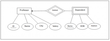
Fig 14 - Example
The Strong Entity is Professor, whereas Dependent is a Weak Entity.
ID is the primary key (represented with a line) and Name in Dependent entity is called Partial Key (represented with a dotted line).
Key takeaway
Entity in DBMS can be a real-world object with an existence, For example, in a College database, the entities can be Professor, Students, Courses, etc.
Entities has attributes, which can be considered as properties describing it, for example, for Professor entity, the attributes are Professor_Name, Professor_Address, Professor_Salary, etc. The attribute value gets stored in the database.
Types of Attributes-
In ER diagram, attributes associated with an entity set may be of the following types-
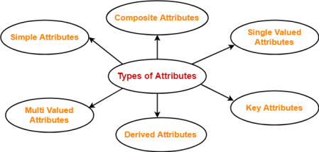
Fig 15 – Types of Attributes
1. Simple Attributes-
Simple attributes are those attributes which can not be divided further.
Example-
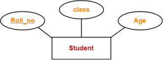
Here, all the attributes are simple attributes as they can not be divided further.
2. Composite Attributes-
Composite attributes are those attributes which are composed of many other simple attributes.
Example-
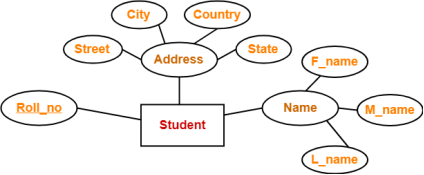
Here, the attributes “Name” and “Address” are composite attributes as they are composed of many other simple attributes.
3. Single Valued Attributes-
Single valued attributes are those attributes which can take only one value for a given entity from an entity set.
Example-
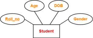
Here, all the attributes are single valued attributes as they can take only one specific value for each entity.
4. Multi Valued Attributes-
Multi valued attributes are those attributes which can take more than one value for a given entity from an entity set.
Example-
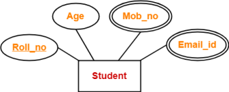
Here, the attributes “Mob_no” and “Email_id” are multi valued attributes as they can take more than one values for a given entity.
5. Derived Attributes-
Derived attributes are those attributes which can be derived from other attribute(s).
Example-
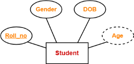
Here, the attribute “Age” is a derived attribute as it can be derived from the attribute “DOB”.
6. Key Attributes-
Key attributes are those attributes which can identify an entity uniquely in an entity set.
Example-
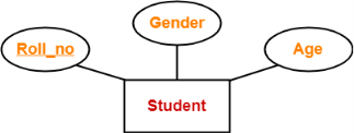
Here, the attribute “Roll_no” is a key attribute as it can identify any student uniquely.
Key takeaway
Database can be represented using the notations. In ER diagram, many notations are used to express the cardinality. These notations are as follows:
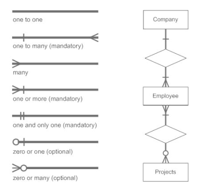
Fig16 : Notations of ER diagram
Key takeaway
Database can be represented using the notations. In ER diagram, many notations are used to express the cardinality.
There are several implicit relationships among the various entity types. In fact, whenever an attribute of one entity type refers to another entity type, some relationship exists. For example, the attribute Manager of DEPARTMENT refers to an employee who manages the department; the attribute Controlling department of PROJECT refers to the department that controls the project; the attribute Supervisor of EMPLOYEE refers to another employee (the one who supervises this employee); the attribute Department of EMPLOYEE refers to the department for which the employee works; and so on. In the ER model, these references should not be represented as attributes but as relationships, which are discussed in this section. The COMPANY database schema will be refined in Section 7.6 to represent relationships explicitly. In the initial design of entity types, relationships are typically captured in the form of attributes. As the design is refined, these attributes get converted into relationships between entity types.
This section is organized as follows: Section 7.4.1 introduces the concepts of relationship types, relationship sets, and relationship instances. We define the concepts of relationship degree, role names, and recursive relationships in Section 7.4.2, and then we discuss structural constraints on relationships—such as cardinality ratios and existence dependencies—in Section 7.4.3. Section 7.4.4 shows how relationship types can also have attributes.
1. Relationship Types, Sets, and Instances
A relationship typeR among n entity types E1, E2, ...,En defines a set of associations—or a relationship set—among entities from these entity types. As for the case of entity types and entity sets, a relationship type and its corresponding relationship set are customarily referred to by the same name, R. Mathematically, the relationship set R is a set of relationship instances ri, where each ri associates n individual entities (e1, e2, ..., en), and each entity ej in ri is a member of entity set Ej, 1 fjfn. Hence, a relationship set is a mathematical relation on E1, E2, ...,En; alter-natively, it can be defined as a subset of the Cartesian product of the entity sets E1×E2×...×En. Each of the entity types E1, E 2, ...,En is said to participate in the relationship type R; similarly, each of the individual entities e1, e2, ..., en is said to participate in the relationship instance ri= (e1,e2, ...,en).
Informally, each relationship instance ri in R is an association of entities, where the association includes exactly one entity from each participating entity type. Each such relationship instance ri represents the fact that the entities participating in ri are related in some way in the corresponding miniworld situation. For example, consider a relationship type WORKS_FOR between the two entity types EMPLOYEE and DEPARTMENT, which associates each employee with the department for which the employee works in the corresponding entity set. Each relationship instance in the relationship set WORKS_FOR associates one EMPLOYEE entity and one DEPARTMENT entity. Figure 7.9 illustrates this example, where each relationship
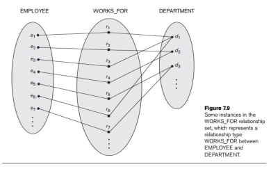
Fig 17 - Example
Instance ri is shown connected to the EMPLOYEE and DEPARTMENT entities that participate in ri. In the mini world represented by Figure 7.9, employeese1, e3, and e6 work for department d1; employees e2 and e4 work for department d2; and employ-eese5 and e7 work for department d3.
In ER diagrams, relationship types are displayed as diamond-shaped boxes, which are connected by straight lines to the rectangular boxes representing the participat-ing entity types. The relationship name is displayed in the diamond-shaped box (see Figure 7.2).
2. Relationship Degree, Role Names, and Recursive Relationships
Degree of a Relationship Type. The degree of a relationship type is the number of participating entity types. Hence, the WORKS_FOR relationship is of degree two. A relationship type of degree two is called binary, and one of degree three is called ternary. An example of a ternary relationship is SUPPLY, shown in Figure 7.10, where each relationship instance ri associates three entities—a supplier s, a part p, and a project j—whenever s supplies part p to project j. Relationships can generally be of any degree, but the ones most common are binary relationships. Higher-degree relationships are generally more complex than binary relationships; we characterize them further in Section 7.9.
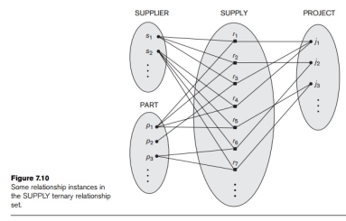
Fig 18 – Supply ternary relationship set
Relationships as Attributes. It is sometimes convenient to think of a binary relationship type in terms of attributes, as we discussed in Section 7.3.3. Consider the WORKS_FOR relationship type in Figure 7.9. One can think of an attribute called Department of the EMPLOYEE entity type, where the value of Department for each EMPLOYEE entity is (a reference to) the DEPARTMENT entity for which that employee works. Hence, the value set for this Department attribute is the set of all DEPARTMENT entities, which is the DEPARTMENT entity set. This is what we did in Figure 7.8 when we specified the initial design of the entity type EMPLOYEE for the COMPANY database. However, when we think of a binary relationship as an attribute, we always have two options. In this example, the alternative is to think of a multivalued attribute Employee of the entity type DEPARTMENT whose values for each DEPARTMENT entity is the set of EMPLOYEE entities who work for that department. The value set of this Employee attribute is the power set of the EMPLOYEE entity set. Either of these two attributes—Department of EMPLOYEE or Employee of DEPARTMENT—can represent the WORKS_FOR relationship type. If both are represented, they are constrained to be inverses of each other.
Role Names and Recursive Relationships. Each entity type that participates in a relationship type plays a particular role in the relationship. The role name signifies the role that a participating entity from the entity type plays in each relation-ship instance, and helps to explain what the relationship means. For example, in the WORKS_FOR relationship type, EMPLOYEE plays the role of employee or worker and DEPARTMENT plays the role of department or employer.
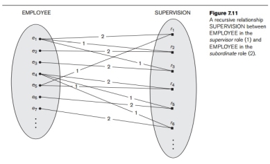
Role names are not technically necessary in relationship types where all the participating entity types are distinct, since each participating entity type name can be used as the role name. However, in some cases the same entity type participates more than once in a relationship type in different roles. In such cases the role name becomes essential for distinguishing the meaning of the role that each participating entity plays. Such relationship types are called recursive relationships. Figure 7.11 shows an example. The SUPERVISION relationship type relates an employee to a supervisor, where both employee and supervisor entities are members of the same EMPLOYEE entity set. Hence, the EMPLOYEE entity type participates twice in SUPERVISION: once in the role of supervisor (or boss), and once in the role of supervisee (or subordinate). Each relationship instance SUPERVISION associates two employee entities ej and ek, one of which plays the role of supervisor and the other the role of supervisee. In Figure 7.11, the lines marked ‘1’ represent the super-visor role, and those marked ‘2’ represent the supervisee role; hence, e1 supervises e2 and e3, e4 supervises e6 and e7, and e5 supervises e1 and e4. In this example, each relationship instance must be connected with two lines, one marked with ‘1’ (supervisor) and the other with ‘2’ (supervisee).
3. Constraints on Binary Relationship Types
Relationship types usually have certain constraints that limit the possible combinations of entities that may participate in the corresponding relationship set. These constraints are determined from the miniworld situation that the relationships rep-resent. For example, in Figure 7.9, if the company has a rule that each employee must work for exactly one department, then we would like to describe this constraint in the schema. We can distinguish two main types of binary relationship constraints: cardinality ratio and participation.
Cardinality Ratios for Binary Relationships. The cardinality ratio for a binary relationship specifies the maximum number of relationship instances that an entity can participate in. For example, in the WORKS_FOR binary relationship type, DEPARTMENT: EMPLOYEE is of cardinality ratio 1:N, meaning that each department can be related to (that is, employs) any number of employees,9 but an employee can be related to (work for) only one department. This means that for this particular relationship WORKS_FOR, a particular department entity can be related to any number of employees (N indicates there is no maximum number). On the other hand, an employee can be related to a maximum of one department. The possible cardinality ratios for binary relationship types are 1:1, 1:N, N:1, and M:N.
An example of a 1:1 binary relationship is MANAGES (Figure 7.12), which relates a department entity to the employee who manages that department. This represents the mini world constraints that—at any point in time—an employee can manage one department only and a department can have one manager only. The relation-ship type WORKS_ON (Figure 7.13) is of cardinality ratio M:N, because the mini
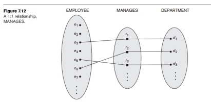
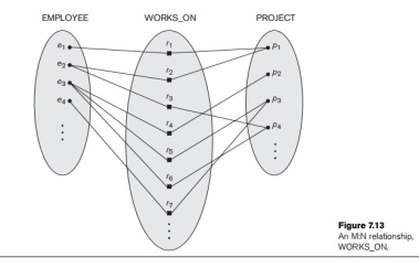
World rule is that an employee can work on several projects and a project can have several employees.
Cardinality ratios for binary relationships are represented on ER diagrams by dis-playing 1, M, and N on the diamonds as shown in Figure 7.2. Notice that in this notation, we can either specify no maximum (N) or a maximum of one (1) on participation. An alternative notation (see Section 7.7.4) allows the designer to specify a specific maximum number on participation, such as 4 or 5.
Participation Constraints and Existence Dependencies. The participation constraint specifies whether the existence of an entity depends on its being related to another entity via the relationship type. This constraint specifies the minimum number of relationship instances that each entity can participate in, and is some-times called the minimum cardinality constraint. There are two types of participation constraints—total and partial—that we illustrate by example. If a company policy states that every employee must work for a department, then an employee entity can exist only if it participates in at least one WORKS_FOR relationship instance (Figure 7.9). Thus, the participation of EMPLOYEE in WORKS_FOR is called total participation, meaning that every entity in the total set of employee entities must be related to a department entity via WORKS_FOR. Total participation is also called existence dependency. In Figure 7.12 we do not expect every employee to manage a department, so the participation of EMPLOYEE in the MANAGES relationship type is partial, meaning that some or part of the set of employee entities are related to some department entity via MANAGES, but not necessarily all. We will refer to the cardinality ratio and participation constraints, taken together, as the structural constraints of a relationship type.
In ER diagrams, total participation (or existence dependency) is displayed as a double line connecting the participating entity type to the relationship, whereas partial participation is represented by a single line (see Figure 7.2). Notice that in this notation, we can either specify no minimum (partial participation) or a minimum of one (total participation). The alternative notation (see Section 7.7.4) allows the designer to specify a specific minimum number on participation in the relationship, such as 4 or 5.
We will discuss constraints on higher-degree relationships in Section 7.9.
4. Attributes of Relationship Types
Relationship types can also have attributes, similar to those of entity types. For example, to record the number of hours per week that an employee works on a particular project, we can include an attribute Hours for the WORKS_ON relationship type in Figure 7.13. Another example is to include the date on which a manager started managing a department via an attribute Start_date for the MANAGES relationship type in Figure 7.12.
Notice that attributes of 1:1 or 1:N relationship types can be migrated to one of the participating entity types. For example, the Start_date attribute for the MANAGES relationship can be an attribute of either EMPLOYEE or DEPARTMENT, although conceptually it belongs to MANAGES. This is because MANAGES is a 1:1 relation-ship, so every department or employee entity participates in at most one relationship instance. Hence, the value of the Start_date attribute can be determined separately, either by the participating department entity or by the participating employee (manager) entity.
For a 1:N relationship type, a relationship attribute can be migrated only to the entity type on the N-side of the relationship. For example, in Figure 7.9, if the WORKS_FOR relationship also has an attribute Start_date that indicates when an employee started working for a department, this attribute can be included as an attribute of EMPLOYEE. This is because each employee works for only one department, and hence participates in at most one relationship instance in WORKS_FOR. In both 1:1 and 1:N relationship types, the decision where to place a relationship attribute—as a relationship type attribute or as an attribute of a participating entity type—is determined subjectively by the schema designer.
For M:N relationship types, some attributes may be determined by the combination of participating entities in a relationship instance, not by any single entity. Such attributes must be specified as relationship attributes. An example is the Hours attribute of the M:N relationship WORKS_ON (Figure 7.13); the number of hours per week an employee currently works on a project is determined by an employee-project combination and not separately by either entity.
Key takeaway
There are several implicit relationships among the various entity types. In fact, whenever an attribute of one entity type refers to another entity type, some relationship exists. For example, the attribute Manager of DEPARTMENT refers to an employee who manages the department; the attribute Controlling_department of PROJECT refers to the department that controls the project; the attribute Supervisor of EMPLOYEE refers to another employee (the one who supervises this employee); the attribute Department of EMPLOYEE refers to the department for which the employee works; and so on. In the ER model, these references should not be represented as attributes but as relationships, which are discussed in this section. The COMPANY database schema will be refined in Section 7.6 to represent relationships explicitly. In the initial design of entity types, relationships are typically captured in the form of attributes. As the design is refined, these attributes get converted into relationships between entity types.
What are Keys in DBMS?
KEYS in DBMS is an attribute or set of attributes which helps you to identify a row(tuple) in a relation(table). They allow you to find the relation between two tables. Keys help you uniquely identify a row in a table by a combination of one or more columns in that table. Key is also helpful for finding unique record or row from the table. Database key is also helpful for finding unique record or row from the table.
Example:
Employee ID | FirstName | LastName |
11 | Andrew | Johnson |
22 | Tom | Wood |
33 | Alex | Hale |
In the above-given example, employee ID is a primary key because it uniquely identifies an employee record. In this table, no other employee can have the same employee ID.
Why we need a Key?
Here are some reasons for using sql key in the DBMS system.
Types of Keys in Database Management System
There are mainly seven different types of Keys in DBMS and each key has it’s different functionality:
What is the Super key?
A superkey is a group of single or multiple keys which identifies rows in a table. A Super key may have additional attributes that are not needed for unique identification.
Example:
EmpSSN | EmpNum | Empname |
9812345098 | AB05 | Shown |
9876512345 | AB06 | Roslyn |
199937890 | AB07 | James |
In the above-given example, EmpSSN and EmpNum name are superkeys.
What is a Primary Key?
PRIMARY KEY is a column or group of columns in a table that uniquely identify every row in that table. The Primary Key can't be a duplicate meaning the same value can't appear more than once in the table. A table cannot have more than one primary key.
Rules for defining Primary key:
Example:
In the following example, <code>StudID</code> is a Primary Key.
StudID | Roll No | First Name | LastName | |
1 | 11 | Tom | Price | abc@gmail.com |
2 | 12 | Nick | Wright | xyz@gmail.com |
3 | 13 | Dana | Natan | mno@yahoo.com |
What is the Alternate key?
ALTERNATE KEYS is a column or group of columns in a table that uniquely identify every row in that table. A table can have multiple choices for a primary key but only one can be set as the primary key. All the keys which are not primary key are called an Alternate Key.
Example:
In this table, StudID, Roll No, Email are qualified to become a primary key. But since StudID is the primary key, Roll No, Email becomes the alternative key.
StudID | Roll No | First Name | LastName | |
1 | 11 | Tom | Price | abc@gmail.com |
2 | 12 | Nick | Wright | xyz@gmail.com |
3 | 13 | Dana | Natan | mno@yahoo.com |
What is a Candidate Key?
CANDIDATE KEY is a set of attributes that uniquely identify tuples in a table. Candidate Key is a super key with no repeated attributes. The Primary key should be selected from the candidate keys. Every table must have at least a single candidate key. A table can have multiple candidate keys but only a single primary key.
Properties of Candidate key:
Example: In the given table Stud ID, Roll No, and email are candidate keys which help us to uniquely identify the student record in the table.
StudID | Roll No | First Name | LastName | |
1 | 11 | Tom | Price | abc@gmail.com |
2 | 12 | Nick | Wright | xyz@gmail.com |
3 | 13 | Dana | Natan | mno@yahoo.com |

What is the Foreign key?
FOREIGN KEY is a column that creates a relationship between two tables. The purpose of Foreign keys is to maintain data integrity and allow navigation between two different instances of an entity. It acts as a cross-reference between two tables as it references the primary key of another table.
Example:
DeptCode | DeptName |
001 | Science |
002 | English |
005 | Computer |
Teacher ID | Fname | Lname |
B002 | David | Warner |
B017 | Sara | Joseph |
B009 | Mike | Brunton |
In this key in dbms example, we have two table, teach and department in a school. However, there is no way to see which search work in which department.
In this table, adding the foreign key in Deptcode to the Teacher name, we can create a relationship between the two tables.
Teacher ID | DeptCode | Fname | Lname |
B002 | 002 | David | Warner |
B017 | 002 | Sara | Joseph |
B009 | 001 | Mike | Brunton |
This concept is also known as Referential Integrity.
What is the Compound key?
COMPOUND KEY has two or more attributes that allow you to uniquely recognize a specific record. It is possible that each column may not be unique by itself within the database. However, when combined with the other column or columns the combination of composite keys become unique. The purpose of the compound key in database is to uniquely identify each record in the table.
Example:
OrderNo | PorductID | Product Name | Quantity |
B005 | JAP102459 | Mouse | 5 |
B005 | DKT321573 | USB | 10 |
B005 | OMG446789 | LCD Monitor | 20 |
B004 | DKT321573 | USB | 15 |
B002 | OMG446789 | Laser Printer | 3 |
In this example, OrderNo and ProductID can't be a primary key as it does not uniquely identify a record. However, a compound key of Order ID and Product ID could be used as it uniquely identified each record.
What is the Composite key?
COMPOSITE KEY is a combination of two or more columns that uniquely identify rows in a table. The combination of columns guarantees uniqueness, though individually uniqueness is not guaranteed. Hence, they are combined to uniquely identify records in a table.
The difference between compound and the composite key is that any part of the compound key can be a foreign key, but the composite key may or maybe not a part of the foreign key.
What is a Surrogate key?
SURROGATE KEYS is An artificial key which aims to uniquely identify each record is called a surrogate key. This kind of partial key in dbms is unique because it is created when you don't have any natural primary key. They do not lend any meaning to the data in the table. Surrogate key is usually an integer. A surrogate key is a value generated right before the record is inserted into a table.
Fname | Lastname | Start Time | End Time |
Anne | Smith | 09:00 | 18:00 |
Jack | Francis | 08:00 | 17:00 |
Anna | McLean | 11:00 | 20:00 |
Shown | Willam | 14:00 | 23:00 |
Above, given example, shown shift timings of the different employee. In this example, a surrogate key is needed to uniquely identify each employee.
Surrogate keys in sql are allowed when
Difference Between Primary key & Foreign key
Primary Key | Foreign Key |
Helps you to uniquely identify a record in the table. | It is a field in the table that is the primary key of another table. |
Primary Key never accept null values. | A foreign key may accept multiple null values. |
Primary key is a clustered index and data in the DBMS table are physically organized in the sequence of the clustered index. | A foreign key cannot automatically create an index, clustered or non-clustered. However, you can manually create an index on the foreign key. |
You can have the single Primary key in a table. | You can have multiple foreign keys in a table. |
Summary
Key takeaway
KEYS in DBMS is an attribute or set of attributes which helps you to identify a row(tuple) in a relation(table). They allow you to find the relation between two tables. Keys help you uniquely identify a row in a table by a combination of one or more columns in that table. Key is also helpful for finding unique record or row from the table. Database key is also helpful for finding unique record or row from the table.
EER is a high-level data model that incorporates the extensions to the original ER model. Enhanced ERD are high level models that represent the requirements and complexities of complex database.
In addition to ER model concepts EE-R includes −
These concepts are used to create EE-R diagrams.
Subclasses and Super class
Super class is an entity that can be divided into further subtype.
For example− consider Shape super class.
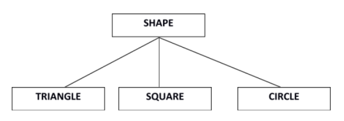
Super class shape has sub groups: Triangle, Square and Circle.
Sub classes are the group of entities with some unique attributes.Sub class inherits the properties and attributes from super class.
Specialization and Generalization
Generalization is a process of generalizing an entity which contains generalized attributes or properties of generalized entities.
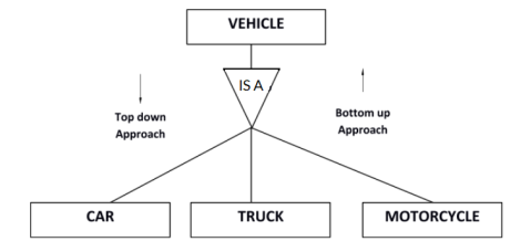
It is a Bottom up process i.e. consider we have 3 sub entities Car, Truck and Motorcycle. Now these three entities can be generalized into one super class named as Vehicle.
Specialization is a process of identifying subsets of an entity that share some different characteristic. It is a top down approach in which one entity is broken down into low level entity.
In above example Vehicle entity can be a Car, Truck or Motorcycle.
Category or Union
Relationship of one super or sub class with more than one super class.
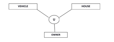
Owner is the subset of two super class: Vehicle and House.
Aggregation
Represents relationship between a whole object and its component.
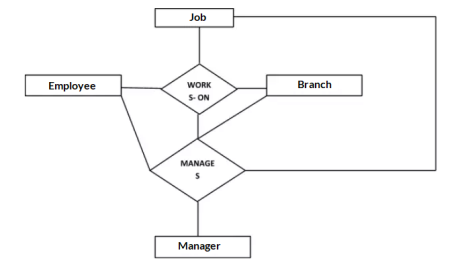
Consider a ternary relationship Works_On between Employee, Branch and Manager. Now the best way to model this situation is to use aggregation, So, the relationship-set, Works_On is a higher level entity-set. Such an entity-set is treated in the same manner as any other entity-set. We can create a binary relationship, Manager, between Works_On and Manager to represent who manages what tasks.
Key takeaway
EER is a high-level data model that incorporates the extensions to the original ER model. Enhanced ERD are high level models that represent the requirements and complexities of complex database.
In addition to ER model concepts EE-R includes −
Specialization
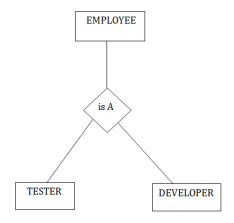
For example: In an Employee management system, EMPLOYEE entity can be specialized as TESTER or DEVELOPER based on what role they play in the company.
Aggregation
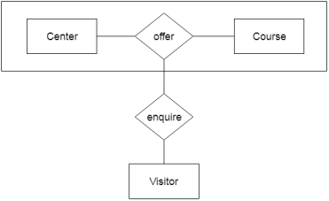
In aggregation, the relation between two entities is treated as a single entity. In aggregation, relationship with its corresponding entities is aggregated into a higher level entity.
For example:Center entity offers the Course entity act as a single entity in the relationship which is in a relationship with another entity visitor. In the real world, if a visitor visits a coaching center then he will never enquiry about the Course only or just about the Center instead he will ask the enquiry about both.
Generalization
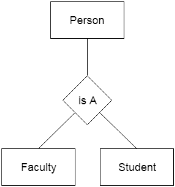
For example, Faculty and Student entities can be generalized and create a higher level entity Person.
Key takeaway
Reference Books
1. “Database Management Systems”, Raghu Ramakrishnan and Johannes Gehrke, 2002, 3rd Edition.
2. “Fundamentals of Database Systems”, RamezElmasri and ShamkantNavathe, Benjamin Cummings, 1999, 3rd Edition.
3. “Database System Concepts”, Abraham Silberschatz, Henry F. Korth and S.Sudarshan, Mc Graw Hill, 2002, 4th Edition.