Unit - 2
Computer Hardware and Software
The word "hardware" refers to the mechanical components of a machine. Computer hardware is made up of interconnected electronic components that can be used to monitor the operation, input, and output of a computer. CPU, keyboard, mouse, hard disk, and other pieces of hardware are examples of hardware.
A computer's hardware is made up of many components that function together. Some components are required, while others are optional. As seen in the image below, computer hardware consists of the CPU and peripherals.
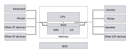
Fig 1: Hardware component
Among the various forms of hardware are:
- Input device - Data is provided to the computer with the aid of these devices. They feed data such as text, image, and sound to the machine and assist in file transfers between devices.
- Output device - This is a computer that transforms data into a readable format for humans. Normally, these devices are used for displaying information. It retrieves data from the computer and shows it to the user. The most visible output device is the computer.
- Storage device - These are the devices that aid in data storage and are separated into primary and secondary memory. The primary memory is RAM (Random Access Memory), which stores data only when the machine is turned on. The central processing unit and the accelerated processing unit read and execute all of the instructions from memory. The microprocessor does not interact directly with secondary memory. This is a non-volatile memory that is split into two types. They really are.
- Internal system – These are the gadgets that are often connected to the screen. Hard disk, for example.
- External device – External devices are plug-and-play devices that attach to the machine. External hard disk, for example.
Hardware organization of a computer
The computer system is a combination of many parts such as peripheral devices, secondary memory, CPU etc. This can be explained more clearly using a diagram.
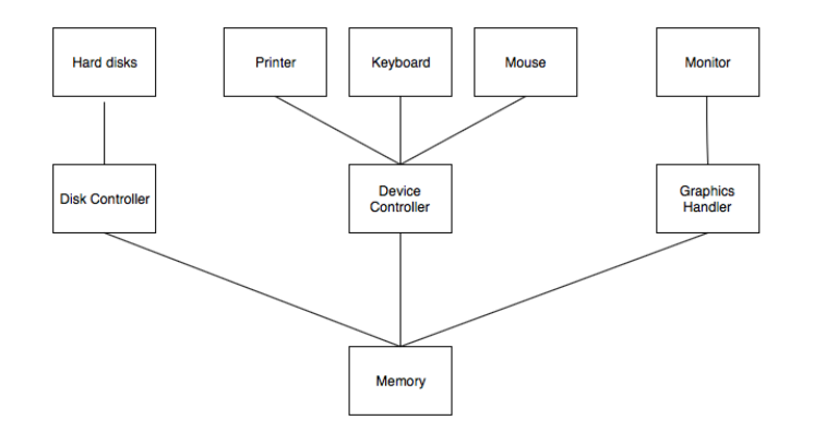
The salient points about the above figure displaying Computer System Organisation is −
● The I/O devices and the CPU both execute concurrently. Some of the processes are scheduled for the CPU and at the same time, some are undergoing input/output operations.
● There are multiple device controllers, each in charge of a particular device such as keyboard, mouse, printer etc.
● There is buffer available for each of the devices. The input and output data can be stored in these buffers.
● The data is moved from memory to the respective device buffers by the CPU for I/O operations and then this data is moved back from the buffers to memory.
● The device controllers use an interrupt to inform the CPU that I/O operation is completed.
Interrupt Handling
An interrupt is a necessary part of Computer System Organisation as it is triggered by hardware and software parts when they need immediate attention.
An interrupt can be generated by a device or a program to inform the operating system to halt its current activities and focus on something else. The types of interrupts are better explained using the following diagram −
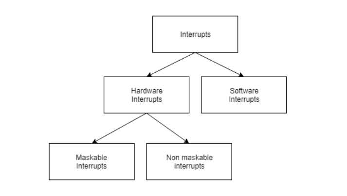
Hardware and software interrupts are two types of interrupts. Hardware interrupts are triggered by hardware peripherals while software interrupts are triggered by software function calls.
Hardware interrupts are of further two types. Maskable interrupts can be ignored or disabled by the CPU while this is not possible for non maskable interrupts.
Key takeaway
The word "hardware" refers to the mechanical components of a machine. Computer hardware is made up of interconnected electronic components that can be used to monitor the operation, input, and output of a computer.
Input Devices are the devices that are used to provide data and instructions to the machine. Depending on the type of data you want to enter in the computer, you can use a variety of input devices, such as a keyboard, mouse, joystick, light pen, and so on.
Keyboard
The keyboard is the most frequent and widely used input device for entering data into a computer. Although there are some additional keys for performing other operations, the keyboard layout is similar to that of a typical typewriter.
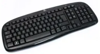
Fig 2: Keyboard
For Windows and the Internet, keyboards come in two sizes: 84 keys or 101/102 keys, but currently keyboards with 104 keys or 108 keys are also available.
The following are the keys on the keyboard:
- Typing Keys - The letter keys (A-Z) and number keys (09) are among these keys, and they have the same layout as typewriters. It is used to enter numeric data or move the cursor.
- Numeric keypad - It usually consists of a set of 17 keys that are arranged in the same way that most adding machines and calculators are.
- Function keys - The keyboard has twelve function keys, which are positioned in a row at the top of the keyboard. Each function key has a distinct significance and serves a distinct purpose.
- Control keys - These keys control the pointer and the screen. There are four directional arrow keys on it. Home, End, Insert, Delete, Page Up, Page Down, Control (Ctrl), Alternate (Alt), and Escape are all control keys (Esc).
- Special purpose keys - Enter, Shift, Caps Lock, Num Lock, Space bar, Tab, and Print Screen are among the special function keys on the keyboard.
Types of keyboards
Depending on the region and language, different keyboards may be available. The following are some of the most frequent keyboard types:
Qwerty keypad - In modern times, it is the most often used keyboard with computers. It is named after the first six letters of the top row of buttons and is popular even in nations where the alphabet is not Latin-based. It is so widespread that some people believe it is the only sort of keyboard that can be used as an input device with computers.
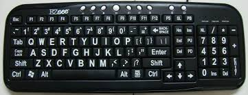
Fig 3: Qwerty keypad
AZERTY Keyboard - The normal French keyboard is this one. It was created in France as a replacement for the QWERTY keyboard, and it is primarily utilized in France and other European countries. Some countries have produced their own AZERTY keyboards.
The first six letters on the top left row of the keyboard are used to create its name. In an AZERTY keyboard, the Q and W keys are swapped with the A and Z keys in a QWERTY keyboard. Furthermore, the M key is to the left of the L key on an AZERTY keyboard.
The AZERTY keyboard differs from the QWERTY keyboard not only in terms of letter layout, but also in a variety of other ways. For example, it emphasizes accents, which is necessary when writing European languages like French.
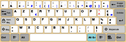
Fig 4: Azerty keyboard
DVORAK Keyboard - This keyboard layout was created to improve typing speed by minimizing finger movement while typing. To improve typing, the most frequently used letters are maintained in a home row.

Fig 5: DVORAK Keyboard
Scanner
With the aid of a scanner, we can save images, photos, and diagrams to the screen. The picture is read by the scanner and saved as a file on the disk.
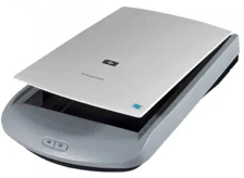
Fig 6: Scanner
Types of scanners
- Flatbed scanner - It has a moving optical CIS or CCD array and a glass window. The image is placed on the glass pane after the light illuminates it. The light passes through the glass window, scanning the page and creating a digital copy. When scanning transparent slides, you'll need a transparency adaptor.
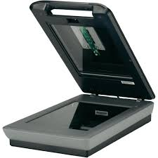
Fig 7: Flatbed scanner
- Handheld scanner - It's a small manual scanning device that's rolled over a flat image to be scanned with your hand. The disadvantage of utilizing this gadget is that it requires the user's hand to be stable when scanning; otherwise, the image may be distorted. The barcode scanner, which you may have seen in stores, is one of the most regularly used handheld scanners.

Fig 8: Handheld scanner
- Sheetfed scanner - The document is put into a slot provided by the scanner in this scanner. The sheet-feeder, scanning module, and calibration sheet are the major components of this scanner. In this scanner, the light does not move. The document instead passes through the scanner. It's just good for scanning single-page documents; it's not good for scanning thick materials like books, periodicals, and so on.
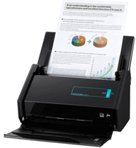
Fig 9: Sheetfed scanner
- Drum scanner - A photomultiplier tube (PMT) is used to scan images in a drum scanner. It lacks a charge-coupled device, such as a flatbed scanner. Light is particularly sensitive to the photomultiplier tube. The image is placed on a glass tube, and light passes through it, producing a reflection of the image that is collected and processed by the PMT. These scanners have a high resolution and are ideal for scanning in great detail.
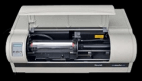
Fig 10: Drum scanner
- Photo scanner - Its purpose is to scan photos. It features a high resolution and color depth, both of which are necessary for scanning photos. Some photo scanners come with software that allows you to clean and restore outdated photos.
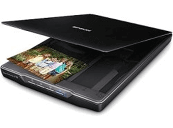
Fig 11: Photo scanner
MICR
The MICR computer input device is designed to read magnetic ink-printed text. MICR (Magnetized Ink Character Recognition) is a character recognition system that uses special magnetised ink that is sensitive to magnetic fields. It's extensively used to handle checks in banks and other companies where security is a top priority. It has the ability to process 300 cheques each minute with 100% accuracy. Magnetic ink is used to write the details on the bottom of the cheque (MICR No.). The magnetic ink can be printed using a laser printer with MICR toner.
The device reads the information and transmits it to a computer for further processing. A document written using magnetic ink must pass through a machine that magnetises the ink and then converts the magnetic information into characters.
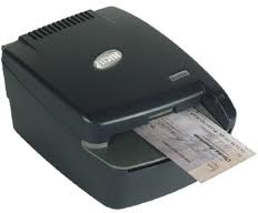
Fig 12: MICR
OCR
OCR (Optical Character Recognition) is a computer input device that converts scanned images of handwritten, typed, or printed text into digital text. It is commonly used to convert documents and books into electronic files in workplaces and libraries.
It uses a scanner to process and copy the physical form of a document. After copying the documents, the OCR programme turns them to a bitmap version, which is a two-color (black and white) version. The image is then evaluated for light and dark areas, with the dark areas chosen as characters and the light areas as background. It's commonly used to convert hard copies of legal or historical documents into PDFs. If necessary, the converted papers can be changed in the same way that we edit documents written in Microsoft Word.
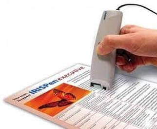
Fig 13: OCR
Key takeaway
Input Devices are the devices that are used to provide data and instructions to the machine. Depending on the type of data you want to enter in the computer, you can use a variety of input devices, such as a keyboard, mouse, joystick, light pen, and so on.
Output Devices are the devices that are used to show the results or details. The display can be seen on a monitor or printed on paper using a printer. The monitor and printer are the most popular output devices.
Printers
This is a vital computer system output unit. It prints out the results that are shown on the computer screen. Printed output is also known as hard copy output because, unlike display output, it can be saved even when the screen is turned off.
There are two types of printers −
● Impact Printers
● Non-Impact Printers
Impact Printers
Impact printers print the characters by striking them on the ribbon, which is then pressed on the paper.
Characteristics of Impact Printers are the following −
● Very low consumable costs
● Very noisy
● Useful for bulk printing due to low cost
● There is physical contact with the paper to produce an image
These printers are of two types −
● Character printers
● Line printers
Character Printers
Character printers are the printers which print one character at a time.
These are further divided into two types:
● Dot Matrix Printer(DMP)
● Daisy Wheel
Dot Matrix Printer
In the market, one of the most popular printers is Dot Matrix Printer. These printers are popular because of their ease of printing and economical price. Each character printed is in the form of pattern of dots and head consists of a Matrix of Pins of size (5*7, 7*9, 9*7 or 9*9) which come out to form a character which is why it is called Dot Matrix Printer.
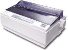
Advantages
● Inexpensive
● Widely Used
● Other language characters can be printed
Disadvantages
● Slow Speed
● Poor Quality
Daisy Wheel
Head is lying on a wheel and pins corresponding to characters are like petals of Daisy (flower) which is why it is called Daisy Wheel Printer. These printers are generally used for word-processing in offices that require a few letters to be sent here and there with very nice quality.
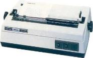
Advantages
● More reliable than DMP
● Better quality
● Fonts of character can be easily changed
Disadvantages
● Slower than DMP
● Noisy
● More expensive than DMP
Line Printers
Line printers are the printers which print one line at a time.
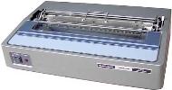
These are of two types −
● Drum Printer
● Chain Printer
Drum Printer
This printer is like a drum in shape hence it is called drum printer. The surface of the drum is divided into a number of tracks. Total tracks are equal to the size of the paper, i.e. for a paper width of 132 characters, drum will have 132 tracks. A character set is embossed on the track. Different character sets available in the market are 48 character set, 64 and 96 characters set. One rotation of drum prints one line. Drum printers are fast in speed and can print 300 to 2000 lines per minute.
Advantages
● Very high speed
Disadvantages
● Very expensive
● Characters fonts cannot be changed
Chain Printer
In this printer, a chain of character sets is used, hence it is called Chain Printer. A standard character set may have 48, 64, or 96 characters.
Advantages
● Character fonts can easily be changed.
● Different languages can be used with the same printer.
Disadvantages
● Noisy
Non-impact Printers
Non-impact printers print the characters without using the ribbon. These printers print a complete page at a time, thus they are also called as Page Printers.
These printers are of two types −
● Laser Printers
● Inkjet Printers
Characteristics of Non-impact Printers
● Faster than impact printers
● They are not noisy
● High quality
● Supports many fonts and different character size
Laser Printers
These are non-impact page printers. They use laser lights to produce the dots needed to form the characters to be printed on a page.
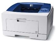
Advantages
● Very high speed
● Very high quality output
● Good graphics quality
● Supports many fonts and different character size
Disadvantages
● Expensive
● Cannot be used to produce multiple copies of a document in a single printing
Inkjet Printers
Inkjet printers are non-impact character printers based on a relatively new technology. They print characters by spraying small drops of ink onto paper. Inkjet printers produce high quality output with presentable features.
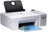
They make less noise because no hammering is done and these have many styles of printing modes available. Color printing is also possible. Some models of Inkjet printers can produce multiple copies of printing also.
Advantages
● High quality printing
● More reliable
Disadvantages
● Expensive as the cost per page is high
● Slow as compared to laser printer
Plotters
A plotter may be used to print a photograph, drawing, or picture stored on a screen. It's a printer output system that produces high-quality printed output. Engineers and architects are the most popular users.
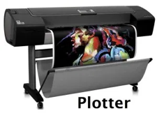
Fig 14: Plotter
A plotter is a type of output device that prints high-quality graphics in a variety of color formats. It's similar to a printer, but with more advanced capabilities. The plotter can print on cardboard, fabric, film, and other synthetic materials, but the printer can only print on paper. T-shirts, backpacks, other lightweight clothes, and even round things like cups can all be printed on with certain special models.
Plotters differ from printers in that they are more precise, faster, and can produce high-resolution graphics. That is why plotters are employed in technical applications by engineers and architects when precision is required. Printers create images based on the commands entered into the computer. In this scenario, different colored pens are utilized to draw multicolor plotters.
The plotter is used to create high-quality graphs on big sheets of paper. It is mostly utilized in engineering, building construction, city planning, map making, and other related fields. When it comes to purchasing, plotters are far more expensive than printers.
Monitors
The most popular output device connected to a computer for displaying processed data is this. It has the appearance of a television and is also known as VDU (Visual Display Unit). Pixels are a large number of very tiny dots on a projector that are used to view pictures. The resolution of a monitor refers to the amount of pixels that can be displayed on its screen.
Since the display on the computer cannot be saved for a long time, it is referred to as Soft Copy Output.
LCD monitors are becoming more common as a result of their sharp picture quality. They are flat-screen displays with a light weight.
The following are the two most popular monitor types:
1. Cathode Ray Tube (CRT)Monitor - The cathode ray tubes are used in CRT monitors. They're similar to vacuum tubes in that they generate visuals in the form of video signals. The electron guns of a cathode ray tube emit a beam of electrons that impact the inner phosphorescent surface of the screen to produce images on the screen. Millions of red, green, and blue phosphorous dots adorn the monitor. When electron beams strike these dots, they begin to glow, a phenomenon known as cathodoluminescence.
The electron gun assembly, deflection plate assembly, fluorescent screen, glass envelope, and base are the primary components of a CRT display. The face plate is the front (outside) surface of the screen where images are projected. Fiber optics make up the structure.
The screen is struck by three electron beams: red, green, and blue. As a result, the colors you see on the screen are a combination of red, blue, and green LEDs. The electron beams are guided by the magnetic field. Despite the fact that LCD monitors have mostly replaced CRT monitors, graphics experts continue to utilize CRT monitors due to their superior color quality.
2. Liquid crystal Display (LCD)Monitor - In comparison to CRT displays, an LCD monitor is a flat panel screen that is tiny and light-weight. It is based on liquid crystal display technology, which is found in laptops, tablets, smart phones, and other electronic devices. A liquid crystal solution is sandwiched between two layers of polarized glass in an LCD panel. An electric current aligns the liquid crystals when light passes through the first layer. The aligned liquid crystals allow variable amounts of light to flow through the second layer, allowing images to be created on the screen.
The image on the LCD screen is shown on the screen by a matrix of pixels. Passive-matrix panels, which control individual pixels by delivering a charge, were used in older LCDs. When images moved quickly on the screen, a few electrical charges could be transferred every second, causing screens to appear fuzzy.
Thin film transistors (TFTs) and capacitors are used in modern LCDs, which utilize active-matrix technology. Pixels can keep their charge with this technology. As a result, when images move quickly on the screen, they do not blur, and they are more efficient than passive-matrix displays.
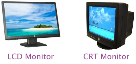
Fig 15: Monitor
LED Displays
The 'Light Emitting Diode,' or LED, is the most recent innovation in the market today, competing with LCDs and Plasma Monitors. These monitors have a slightly curved or flat panel display with light-emitting diodes (LEDs) for illumination instead of cold cathode fluorescent (CCFL) backlighting.
LED screens with 4k resolution are brighter than other displays, allowing the user to be read or seen readily in daytime. LED monitors utilise less electricity than LCD monitors, and they're popular among gamers who want to play high-resolution games.
LEDs have the advantage of producing visuals with increased contrast and bright colours, as well as having no negative environmental impact when discarded. Furthermore, LED monitors are more durable than LCD and CRT monitors.
The wavelength range of the lights used is such that they provide excellent quality. The flicker-free image produced by these LED screens reduces eye strain, fatigue, and headaches.
These displays have a longer life span, consume less electricity, are slimmer, have better contrast and colours, and have a lower environmental effect than LCDs.
LED monitors can be quite costly, making them out of reach for some individuals.
The display technology has evolved dramatically during the last decade. LED screens are one of the most recent innovations.
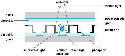
This is the field. Light emitting diodes (LEDs) are used in LED monitors to improve performance. LED monitors are LCD monitors that use an LED backlight to illuminate the LCD panel. It means that LEDs are placed behind or around the LCD display to improve the monitor's brightness and video definition.
LCD monitors employ a cold cathode light as backlight, as we saw in the previous part. All of the concepts are the same with LED displays, except for the backlight, which is replaced by LEDs.
Based on how the diodes are arranged in the display, there are three main types of LED monitors available. Direct LEDs, Edge LEDs, and RGB LEDs are the three types. White diodes are utilised to illuminate the LCD panel in both Edge and Direct LED display displays to offer increased picture quality. The following image depicts the LED layout in the monitor:
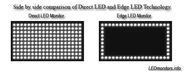
Fig 16: An Image Showing Comparison of Direct LED and Edge LED Technology
White diodes are placed all over the panel in the Direct LEDs display to provide a higher quality image, whereas LEDs are only used on the LCD panel's borders in the Edge LEDs display. Direct LEDs are commonly employed in the manufacture of high-definition televisions, whereas Edge LEDs are mostly used in the manufacture of computer screens. RGB LED displays are the best of the three types of LED displays because they use red, green, and blue diodes to produce lifelike images with a high contrast ratio.
History of LED displays
In 1977, James P. Mitchell is widely credited with developing the first LED display. On March 18, 1978, the public saw the first LED display prototype at the SEF (Science and Engineering Fair) in Iowa. On May 8, 1978, it was screened at the SEF in Anaheim, California. General Motors and NASA recognised the prototype, which was 1/4-inch thick.
OLED Display
Organic Light Emitting Diode, or OLED, is the most recent display technology. As the name implies, an organic substance (one that contains carbon, such as wood, plastic, or polymers) is utilised to convert electric current into light. Because LEDs can create several colours of light, they are directly employed to produce the desired colour, eliminating the need for a backlight, saving both power and space. OLED displays are unquestionably superior to existing display technologies in terms of response time, viewing angles, contrast levels, and brightness.
Fig 17: Image of OLED or Organic Light Emitting Diode Monitors
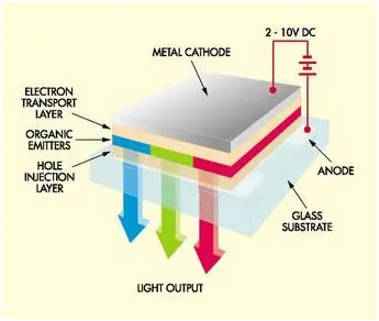
Fig 18: A Diagram Illustrating Structure and Working of a OLED Display
A stack of thin organic layers is sandwiched between two conductors – a transparent anode and a metallic cathode – which are sandwiched between two glass plates known as seal and substrate. A hole-injection layer, a hole-transport layer, an emissive layer, and an electron-transport layer make up the organic layer. An electric current passes from the cathode to the anode through the organic layers when the suitable voltage is supplied. The cathode provides electrons to the emissive layer of organic molecules, while the anode receives comparable electrons from the conducting layer. Electrons and holes congregate at the interface between emissive and conductive layers.
By releasing energy in the form of a photon of light, electrons are recombined with holes. As a result, the organic layer emits light to create the show. The hue of the light is determined by the type of organic molecules present, and the brightness is determined by the current applied. In OLED devices, the output light can be increased by enhancing the recombination process in the emissive layer. To improve the electro-luminescent efficiency and colour control, the emissive layer is gently doped with highly fluorescent molecules.
Advantages of organic LEDs
The fundamental advantage of an organic LED over an LCD is that it is more smaller, more flexible, and lighter. LCDs are typically 10 times thicker than OLEDs, which have a thickness of 0.2 to 0.3 mm. Because OLED displays do not require a backlight, they consume less energy than LCD displays. As a result, portable gadgets using OLEDs, such as smartphones, have a longer useable battery life.
When watching sports or other fast-moving images, LCDs typically take longer to respond, whereas OLEDs can refresh up to 200 times faster. When compared to LCDs, they also have a significantly wider viewing angle and display truer colours. OLED TVs boast the best contrast of any TV technology since each image pixel produces its own light and is not lighted by a backlight.
Disadvantages of organic LEDs
One major disadvantage of OLED screens is their short lifespan. Because organic molecules degrade over time, OLEDs can degrade up to four times faster than conventional LED and LCD screens. Manufacturers, on the other hand, are working hard to discover engineering solutions.
Another disadvantage is that organic molecules are water sensitive, which can cause issues for mobile electronics such as smartphones that may be exposed to higher humidity or difficult settings. Also, OLEDs are currently pricey, but as their popularity grows, they will become less so.
Key takeaway
Output Devices are the devices that are used to show the results or details. The display can be seen on a monitor or printed on paper using a printer. The monitor and printer are the most popular output devices.
Mouse
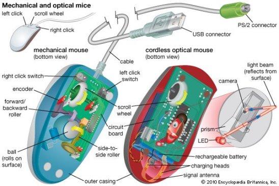
Another input device that is usually used with computers is the mouse. It's essentially a pointing system that operates on the Point and Click principle. When the mouse is pushed over the mouse pad, a light beam reflects under it, causing the cursor on the screen to turn.
The mouse is used in Windows-based applications, where the user can execute commands by using the pointer to point to objects and pressing the mouse buttons. We also use the mouse to draw in paint and take pictures of the kids.

Fig 19: Mouse
Most modern mice now have a wheel in the center of two buttons that allows us to scroll through documents more quickly. To scroll up or down in a book, we use our forefinger to turn the wheel. The optical mouse tracks the movement of the mouse to shift the cursor on the computer screen using red light.
Advantages
- Easy to use
- Not very expensive
- Moves the cursor faster than the arrow keys of the keyboard
Types of Mouses
1. Trackball mouse - It is a stationary input device that moves the pointer or cursor on the screen using a ball mechanism. The ball is half-inserted in the device and may be simply rolled to move the pointer on the screen with a finger, thumb, or palm. The device features a sensor that detects ball rotation. It does not need to be moved on the operating area; it remains stationary. As a result, it's a great device for people with limited work space because it doesn't require as much movement as a mouse.
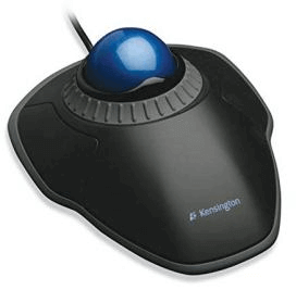
Fig 20: Trackball mouse
2. Mechanical mouse - To track its movement, it uses a ball and numerous rollers. It's a mouse with a cord. For great performance, a mechanical mouse can be used. The disadvantage is that they tend to collect dust in the mechanics, necessitating routine cleaning.
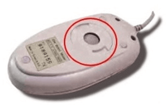
Fig 21: Mechanical mouse
3. Optical mouse - Optical electronics are used to track the movement of an optical mouse. It is more dependable and requires less maintenance than a mechanical mouse. The surface on which it is used, however, has an impact on its performance. For optimal results, use a plain, non-glossy mouse mat. The shiny surface may reflect light incorrectly, causing tracking issues, and the rough surface may cause problems for the optical identification system.
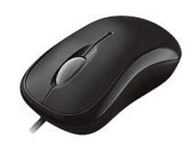
Fig 22: Optical mouse
4. Wireless mouse - This sort of mouse does not have a cable and instead uses wireless technologies such as IrDA (infrared) or radio (Bluetooth or Wi-Fi) to control cursor movement. It's used to make using a mouse more enjoyable. It gets its energy from batteries.
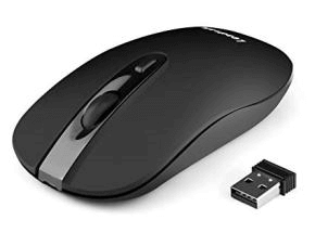
Fig 23: Wireless mouse
Basic parts
A mouse typically has two buttons: a primary button (usually the left button) and a secondary button (usually the right button). The primary button is the one you will use most often. Most mice also include a scroll wheel between the buttons to help you scroll through documents and WebPages more easily. On some mice, the scroll wheel can be pressed to act as a third button. Advanced mice might have additional buttons that can perform other functions.
Joystick
Joysticks and gamepads are examples of input devices that are used to guide the movement of objects on a computer screen. These, like the mouse, are pointing instruments. They are mostly used to play video games.
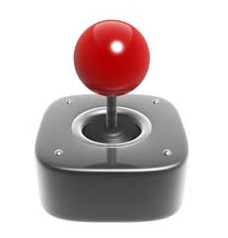
Fig 24: Joystick
A vertical stick with a trackball at the bottom of the joystick. The user needs to shift the items on the screen quickly when playing video games. Objects can be easily pushed in all directions with the movement of this vertical stick.
C. B. Mirick of the US Naval Research Laboratory designed the first joystick. Different varieties of joysticks exist, including displacement joysticks, finger-operated joysticks, hand-operated joysticks, isometric joysticks, and more. The pointer in a joystick continues to travel in the direction of the joystick until it is upright, whereas the cursor in a mouse moves only when the mouse moves.
Touch Screen
A touch screen is a display that also functions as an input device. Touching images or phrases on the screen allows users to interact with computers. Because the screens are pressure-sensitive, when a user touches them with their finger or pen, the event is recorded and sent to a controller for processing. Pictures or phrases on a touch screen can assist users in operating devices.
Touch screens are an alternative to a mouse or keyboard for navigating a GUI and also provide a simpler way to input data. Touch screens are found in a variety of devices, including smartphones, information kiosks, laptops, laptop displays, tablets, and cash registers. Some touch screens detect the presence of a finger using a grid of infrared beams rather than touch-sensitive input.
Despite the fact that it appears to be a basic display screen, it incorporates multiple layers that recognise input. The first layer is the hard protective, which protects touchscreen components and the actual display. Underneath the protective covering is an electrical grid that recognises user input.
Instead of employing a grid, most current touchscreens use capacitive material, which alters the electrical charge when the screen is touched. The LCD layer is found beneath the touchscreen layer and is responsible for the actual display.
Touch screen technologies
Touch screens are not all the same since they use different technologies to allow users to communicate with a screen. Some technologies only allow input from stylus-equipped devices, while others only take input from your finger.
The three most common touch screen technologies are briefly detailed below.
Capacitive
This screen is constructed of an electrically charged material with electronics in each corner that monitor it. The capacitance of the capacitive screen varies as users contact it, allowing the location to be sent and identified. It has the advantage of exceptional clarity and is impervious to dust and water. It also has the drawback of not being able to be utilised with a stylus and instead requiring the use of a bare finger. When wearing gloves and attempting to utilise a smartphone touch screen, the majority of people are unable to do anything.
Resistive
On a resistive touch screen, a thin metallic layer that is both conductive and resistant detects the pressure of your finger or another item. This technology is often a more appropriate answer than capacitive technology. It can, however, be damaged if it comes into contact with sharp items. It has the advantage of not being destroyed by water or dust while responding to a finger or stylus. It is also less expensive. It has one drawback: it can be damaged by a sharp item and only gives 75% clarity.
Surface acoustic wave (SAW)
When a surface wave touch screen is touched, it registers changes in the waves it detects and generates ultrasonic waves. This technique is more advanced than the other two technologies, capacitive and resistive. However, it is susceptible to the elements and does not function with hard materials. It has the advantage of being easily touched with a finger or stylus. It also has a drawback: it might be damaged by dust or water.
Motherboard
A motherboard, also known as an mboard, mobo, mainboard, modb, base board, backplane board, system board, planar board, or main circuit board, is the principal board and foundation of a computer. It's known as a logic board on Apple computers.
The motherboard in the computer houses the CPU, memory RAM expansion slots, ROM, USB ports, and PCI slots. It establishes communication between the RAM, CPU, and other hardware components.
It also has controllers for things like a keyboard, mouse, hard disc, and DVD drive. A chipset is a collection of controllers and chips found on each motherboard. At the period of development, every new motherboard employs a new chipset. Although newer motherboards are typically quicker and more efficient than their predecessors, older components are frequently incompatible with new chipsets.
There are numerous different sorts of motherboards that are designed to fit into various types and sizes of computers. Because motherboards are intended to function with specific types of memory and processors, they cannot work with all types of memory and processors.
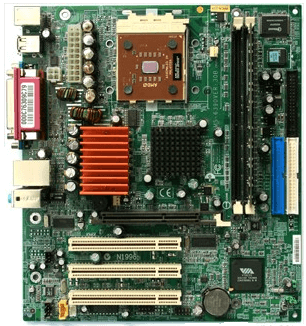
Fig 25: Motherboard
Features of Motherboard
The features of a motherboard are as follows:
● The ability of a motherboard to accommodate various types of components varies substantially.
● A single type of CPU and a limited number of memory types are supported by the motherboard.
● To work effectively, video cards, hard discs, and sound cards must be compatible with the motherboard.
● To work successfully, motherboards, casings, and power supplies must all be compatible.
Description of Motherboard
The motherboard is secured within the chassis with tiny screws that go through pre-drilled holes. All of the internal components are connected via ports on the motherboard. It has a single CPU socket, however one or more memory slots are usually available. Ribbon cables are used to connect the floppy drive, hard drive, and optical drive to the motherboard. Fans and a specific power supply port are included on the motherboard.
Video cards, sound cards, and other expansion cards can be attached to the motherboard via a peripheral card slot in front of the motherboard.
Motherboards have a number of ports on the left side for connecting the monitor, printer, mouse, keyboard, speaker, and network cables. USB ports on motherboards allow compatible devices to be connected in a plug-in/plug-out mode. Pen drives, digital cameras, and other such items are examples.
Ports
A port is a connection or a jack provided on a computer to connect external or peripheral devices to the computer, for example, you will need a port on your device to connect a keyboard, mouse, pen-drives, etc. So, it acts as an interface or a point of attachment between computer and external devices. It is also called a communication port, as it is the point where you plug in a peripheral device to allow data transfer or communication between the device and computer. Generally, they are four to six in number and present on the back or sides of the computer.
Based on the type of protocol used for communication, computer ports can be of two types: Serial Ports and Parallel Ports.
Serial Port:
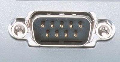
This type of ports provides an interface to connect to peripheral devices using a serial protocol. In this port, the rate of transmission of data is one bit at a time through a single communication line. For example, D-Subminiature or D-sub connector is a commonly used serial port, which carries RS-232 signals.
Parallel Port:
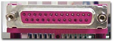
As the name suggests, a parallel port is an interface that allows communication or data transfer between a computer and a device in a parallel manner through more than one communication line. For example, a printer port is a parallel port.
Examples of Computer Ports:
1) PS/2:
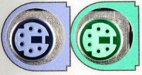
As the name suggests, it was introduced with IBM's Personal Systems/2 series of computers. These connectors are colour coded, e.g., green was for mouse, and purple was for the keyboard. Besides this, it is a DIN connector with six pins. At present, it is superseded by USB ports.
2) VGA Port:
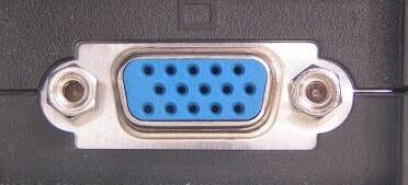
This port is commonly found in computers, projectors, and high definition TVs. It is a D-sub connector called DR-15 as it has 15 pins, which are arranged in 3 rows with five pins in each row. It was most often used to connect CPU with CRT monitors. Still, most of the LCD and LED monitors come with VGA ports. However, these ports don't assure high picture quality as VGA can carry only analogue video signals up to a resolution of 648X480.
As the demand and emphasis on video quality kept growing, the VGA ports were gradually replaced by more advanced ports that can assure high video quality such as HDMI and Display Ports.
3) Digital Video Interface (DVI):
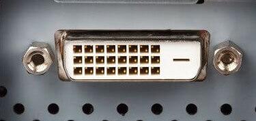
It is another interface between a CPU and a monitor. It is a high-speed interface that is developed to transmit the lossless digital video signals and to replace analogue digital video signal transmission through VGA technology.
The DVI interface can be of three types based on the signals transmitted by it: DVI-I, DVI-D, and DVI-A. The DVI-I supports combined digital and analogue signals, whereas DVI-A supports only analogue signals, and DVI-D supports only digital signals.
Mini-DVI: As the name suggests, it is smaller than a commonly used DVI port. It is a 32 pin port developed by Apple as a substitute to Mini-VGA port. It can transmit various types of signals such as S-Video, VGA, and composite signals using respective adapters.
4) Display Port:

This interface allows transmitting a video and audio from a device to a display screen. It is an advanced display technology that is developed as a substitute for older interfaces such as DVI and VGA. A display port can be seen on laptops, desktops computers, tablets, monitors, etc. It has a 20-pin connector and offers a better resolution than DVI port.
5) RCA Connector:
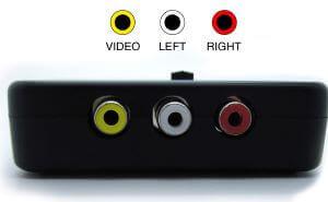
It is designed to accept composite video and stereo signals transmitted by three cables called RCA cable. A RAC cable has three color-coded plugs that are connected to the three corresponding coloured jacks of an RCA connector. Each of the coloured jack is ringed with metal. The red jack supports the right stereo channel, and the white one supports the left stereo channel, while the yellow is used for composite video.
6) Component Video:
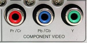
This interface allows splitting video signals into three channels. The component video generally has three color-coded slots; Red, Blue, and Green. Each slot receives and then transmits a particular component of the video signal. It offers high-quality videos than composite video and can carry both analogue and digital video signals.
7) HDMI port:
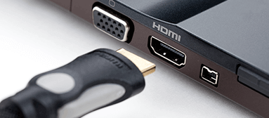
HDMI (High Definition Media Interface) is a digital interface developed to connect high definition devices such as digital cameras, gaming consoles, etc., to computers and TVs with HDMI ports. Besides this, it can carry uncompressed video and uncompressed or compressed audio signals. The advanced version of HDMI, such as 2.0, can transfer video signals of up to a resolution of 4096x2160.
8) USB:
USB (Universal Serial Bus) port is very versatile in use; It can be used for various purposes, such as to transfer data, to connect peripheral devices, and even as an interface for charging devices such as smartphones, digital cameras, etc. Today, it has replaced PS/2 connectors, game ports, serial and parallel ports, etc.
Types of USB ports:
USB Type A:
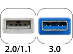
It is a four-pin connector and has many versions that include USB 1.1, USB 2.0 and USB 3.0, and USB 3.1. Version 3.0 is a common standard that supports a data transfer rate of upto 400 MBps. Version 3.1 allows a data rate of upto 10 Gbps.
USB Type C:
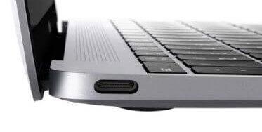
It is the latest design of the USB that comes with 24 pins and can handle a current of 3A. As it can handle high current, it is also used in devices for fast charging. This port was developed by the USB Implementers Forum (USB-IF). One of the distinguishing features of this port is that it has no up or down orientation, which means you don't need to flip the male connecter over to plug it in the USB port. For example, a USB-C plug is symmetrical, so that it can be inserted or plugged in either way.
9) RJ-45:
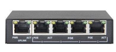
It is an Ethernet style network port found on the computer and other devices such as routers, switches, etc. This port allows your computer to interact or communicate with other computers and networking devices where Ethernet networking is required.
Its full form is Registered Jack 45. It is also known as Ethernet port, network jack, or RJ45 jack. It has eight pins; accordingly, the RJ45 cable comprises eight separate wires of different colours. Besides this, it looks like a telephone jack; however, it is slightly wider than that.
10) RJ11:
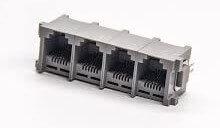
It is also a registered jack, which is often used as an interface for modem, ADSL, and telephone and for terminating the telephone wires. Although it looks like RJ45, it is different from that as it is smaller and has only six pins; it is a 6P4C connector that shows it has six pins with four contacts. This port is mainly used to connect to dial-up modems and is also known as a phone connector, modem port, phone jack, etc.
11) 3.5 mm Audio Jack:
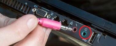
It is a small round connector, port, or an audio jack commonly found on laptops, computers, phones, etc. It is designed to connect to wired headphones and speakers. In other words, it accepts a pin-shaped plug from a headphone, earphone, etc. The measurement "3.5 mm" denotes the diameter of the connector.
However, in older devices, there were two audio jacks, one for mic and another one for headphone. Besides this, they have a 2.5 mm jack or port for phone headphones.
HDD
It is also known as a hard disc drive, "disc drive," (hard drive), or hard disc. It's a data-storage device that's made of a hard magnetic disc. It is housed within a drive unit and saves data indefinitely.
A hard drive is another name for a hard disk. As a non-volatile storage device, it is a hard magnetic disc that saves data permanently. The hard disk is housed in a drive unit on the motherboard of the computer and consists of one or more platters encased in an airtight housing. By rotating a magnetic head over the platters as they spin, data is written on them. The operating system, installed software, and the user's files and programs, such as images, music, movies, and text documents, are all saved on a computer's hard drive.
Component of hard drive
A head actuator, read/write actuator arm, read/write head, platter, and spindle are the key components of a hard disk. On the back of a hard drive, there is a circuit board known as the disk controller or interface board. It allows the computer to connect with the hard disk.
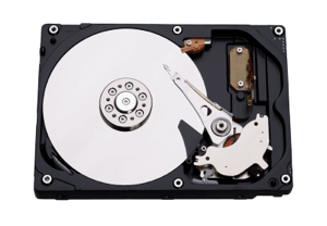
Fig 26: Hard disks
HDD interface types
● 40 pin IDE male connector on the motherboard.
● 50 pin SCSI connector
● SATA connector
● USB connector.
Advantages of Hard Disk Drive (HDD)
Hard disc drives have the following advantages:
● One of the most significant benefits of a hard disc drive is its low cost.
● Another advantage of hard disc drives is their widespread availability.
● Optical discs are slower than hard disc drives.
● HDDs have a large amount of storage capacity.
Disadvantages of Hard Disk Drive (HDD)
Hard Disk Drives have the following drawbacks or limitations:
● The read and write speeds of HDDs are slower than RAM.
● HDDs are noisy devices.
● The inefficiency of HDDs is another issue.
● HDDs use more energy.
● HDDs have a larger physical footprint than SSDs.
CPU
Central Processing Unit (CPU) consists of the following features −
● CPU is considered as the brain of the computer.
● CPU performs all types of data processing operations.
● It stores data, intermediate results, and instructions (program).
● It controls the operation of all parts of the computer.
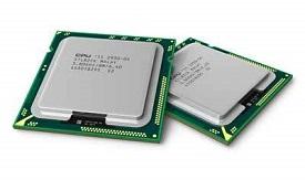
CPU itself has following three components.
● Memory or Storage Unit
● Control Unit
● ALU(Arithmetic Logic Unit)
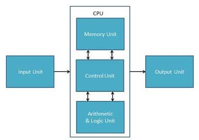
Memory or Storage Unit
This unit can store instructions, data, and intermediate results. This unit supplies information to other units of the computer when needed. It is also known as internal storage unit or the main memory or the primary storage or Random Access Memory (RAM).
Its size affects speed, power, and capability. Primary memory and secondary memory are two types of memories in the computer. Functions of the memory unit are −
● It stores all the data and the instructions required for processing.
● It stores intermediate results of processing.
● It stores the final results of processing before these results are released to an output device.
● All inputs and outputs are transmitted through the main memory.
Control Unit
This unit controls the operations of all parts of the computer but does not carry out any actual data processing operations.
Functions of this unit are −
● It is responsible for controlling the transfer of data and instructions among other units of a computer.
● It manages and coordinates all the units of the computer.
● It obtains the instructions from the memory, interprets them, and directs the operation of the computer.
● It communicates with Input/Output devices for transfer of data or results from storage.
● It does not process or store data.
ALU (Arithmetic Logic Unit)
This unit consists of two subsections namely,
● Arithmetic Section
● Logic Section
Arithmetic Section
Function of arithmetic section is to perform arithmetic operations like addition, subtraction, multiplication, and division. All complex operations are done by making repetitive use of the above operations.
Logic Section
Function of logic section is to perform logic operations such as comparing, selecting, matching, and merging of data.
SMPS
Switched-Mode Power Supply (SMPS) stands for switched-mode power supply. It is an electronic power supply that converts electrical power effectively using a switching regulator. Switching Mode Power Supply is another name for it. It is a power supply unit (PSU) that is used in computers to convert voltage into a range that is acceptable to the computer.
This gadget contains power-handling electronic components that efficiently convert electrical power. To reduce total power loss, a Switched Mode Power Supply employs an excellent power conversion technique.
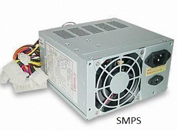
Fig 27: SMPS
How does SMPS work
To regulate and stabilise the output voltage, the SMPS device employs switching regulators that turn on and off the load current. The proper power for a gadget is produced by averaging the voltage between off and on. Unlike linear power supplies, SMPS pass transistors swing between low dissipation, full-on and full-off mode quickly and spend little time in high-dissipation transitions, reducing wasted energy.
Uses
● Rectifiers and invertors are used to convert analogue current to direct current and vice versa. Similarly, frequency changers are used in AC-AC while convertors are used in DC-DC.
● To produce regulated dc output voltage by stepping up or down an uncontrolled dc input voltage.
● Using various converters, invert and provide numerous dc output voltage for appropriate parts.
● Short-circuit and overload protection.
Advantages of the switched-mode power supply
● Efficiency: Because this supply has switching action, very little energy is dissipated in the form of heat. As a result, its efficiency ranges from 68 percent to 90 percent.
● Compact size: the switched-mode power supply is small in size. As a result, they can be made smaller.
● Versatile technology: This technology can be used to deliver high-efficiency voltage conversions in voltage step up (or "Boost") or step down (or "Buck") applications.
● It has a high power density.
● Instead of varying input supply voltage, it features controlled and stable outputs.
● It has a wide ac input voltage range, which makes it lighter than other linear power supplies.
Disadvantages of the switched-mode power supply
● Prices: Before developing the system, we must carefully evaluate the expenses of a switched-mode power supply. • If further filtering is required, it increases the system's value.
● Noise: The transient spikes that occur during the switching process are the most serious concern with switched-mode power supplies. These spikes can produce electromagnetic interference, which can impact other surrounding electronic equipment.
● External components: Although we can construct a switch mode regulator using a single integrated circuit, external components are usually required. The series switch element may be embedded within the integrated circuit in some designs, but it will be an external component if any current is consumed. External components require more room and cost.
● Expert design is required: Some experts are required so that the required specifications can be met.
A computer bus is made up of a series of parallel conductors that can be wires, copper tracks on a printed circuit board, or minuscule aluminium trails on a silicon chip's surface. Because each wire carries just one bit, the number of wires on the bus specifies the maximum data WORD it can broadcast: a bus with eight wires can only transmit 8-bit data words, defining the device as an 8-bit device.
On either end of a computer bus, a single word memory circuit called a LATCH stores the word being transferred quickly and guarantees that each bit has settled to its intended state before its value is transmitted.
The computer bus facilitates communication between the many components of the computer. There would be an unmanageable quantity of cables linking every part to every other part if there was no bus. It would be the equivalent of having individual wiring for each light bulb and outlet in your home.
Data bus
● The data bus is used to transfer data between the microprocessor (CPU) and memory (RAM).
● Is a path on the motherboard that connects the CPU, memory, and other components.
● These lines are used to convey data from one system component to another.
● Because each bus line can only transfer one bit at a time, the number of bus lines enhances the speed of data transfer.
The data bus transports data from one part of the computer to another. These lines contain the meaningful data that will be sent or retrieved from a device. A data bus is used by the CPU to transport data. A 16-bit or 32-bit data bus is possible. It is an electrical channel that connects the motherboard's CPU, memory, and other hardware devices. These lines are bidirectional, allowing data to flow in both directions between the processor and peripheral devices.
The number of wires in the bus influences the speed at which data can flow between hardware components, just as the number of lanes on a highway influences the time it takes for passengers to arrive at their destination. Each wire can transport one bit of data at a time; an eight-wire bus can move eight bits at a time, or one byte of data. Two bytes can be transferred on a 16-bit bus. 32-bit can transport four bytes, for example. The data bus of the Intel 80286 CPU was 16 bits wide. The data bus of the Intel 80386 was 32 bits. More data can be exchanged as the data bus width widens.
Address bus
The address bus transports data location information in memory.
The number of wires in the bus influences the speed at which data can flow between hardware components, just as the number of lanes on a highway influences the time it takes for passengers to arrive at their destination. Each wire can transport one bit of data at a time; an eight-wire bus can move eight bits at a time, or one byte of data. Two bytes can be transferred on a 16-bit bus. 32-bit can transport four bytes, for example. The data bus of the Intel 80286 CPU was 16 bits wide. The data bus of the Intel 80386 was 32 bits. More data can be exchanged as the data bus width widens.
The address bus is a set of links between the processor and memory that transmit signals related to the addresses that the CPU is currently processing, such as the places that it is reading from or writing to. The address bus is used by the processor to identify a peripheral or memory location.
The CPU could only address (i.e. 2^8) 256 bytes of RAM if the address bus could convey 8 bits at a time. Most early PCs used 20-bit address buses, allowing the CPU to address up to 2^20 bytes (1 MB) of data. Today's CPUs can access 4 GB (nearly a billion bytes) of RAM using 32-bit address buses. More information may be processed at a time when the bus path is wider, hence it affects computer processing speed.
Purpose of Address Bus
The address bus connects the CPU to the memory and conveys the address from which the CPU will write. The amount of memory that the CPU can address is determined by the number of bits in the address bus.
Example
Modern PCs contain up to 36 address lines or buses, allowing them to access up to 64 GB of main memory. Due to chipset and motherboard limits, the actual amount of RAM that can be accessed is frequently substantially less than this theoretical limit.
Key takeaway
A computer bus is made up of a series of parallel conductors that can be wires, copper tracks on a printed circuit board, or minuscule aluminium trails on a silicon chip's surface.
Software
A program is a series of instructions that directs a machine to perform specific tasks. Software instructions are written in a programming language, then converted into machine code and executed by the computer.
Advantages of software -
- Computer software's greatest benefit is that it lowers the cost of manual labor. Every piece of software has been created with a particular purpose in mind. The app allows you to store and retrieve information easily.
- In today's industry, there are several different types of applications. Education, jobs, workplaces, entertainment, pharmacy, law, airlines, railways, and a variety of other fields all rely heavily on computer software.
- Not to mention the dangers that computers and software have brought, such as fraud, hacking, and computer viruses.
- When we consider all of the applications of software in the modern world, we can see that there are many advantages in the way we interact and conduct business.
Types
There are two types of software available -
- System software
- Application software
Key takeaway
A program is a series of instructions that directs a machine to perform specific tasks. Software instructions are written in a programming language, then converted into machine code and executed by the computer.
System software
Software is a part of computer system that contains data or set of instructions. It is considered as set of programs, which is then executed to perform a well-defined function. A program consists of a set of instructions which are used to perform a specific task in an orderly manner.
There are two types of software −
● System Software
● Application Software
System Software
The system software is a group of programs designed to operate, control, perform and extend the processing capabilities of the computer itself. System software is generally prepared by the computer manufacturers. These software products contain mainly programs which are written in low-level languages, understandable language where they interact with the hardware at a very basic level. It is very cumbersome to write a program in the machine language. System software acts as the interface between the hardware and the end users.
Some examples of system software are Operating System, Compilers, Interpreter, Assemblers, etc.

Here is a list of some of the most prominent features of a system software −
● Close to the system
● Very fast in speed
● Complicated to design
● Difficult to understand
● Less interactive
● Smaller in size
● Difficult to manipulate
● Generally written in low-level language i.e machine language
Application Software
Application software products are specially designed to satisfy the needs of the user to perform the functions properly. All software applications prepared in the computer lab can come under the category of Application software.
Application software may consist of a single program, such as Microsoft's notepad. It is used to write and edit a simple text. It may also consist of a series of programs, often called a software package, which work together to perform a specific task, such as a spreadsheet package.
Examples of Application software are the following −
● Payroll Software
● Student Record Software
● Inventory Management Software
● Income Tax Software
● Railways Reservation Software
● Microsoft Office Suite Software
● Microsoft Word
● Microsoft Excel
● Microsoft PowerPoint

Features of application software are as follows −
● Close to the user
● Easy to design
● More interactive
● Slow in speed
● Generally written in high-level language
● Easy to understand
● Easy to manipulate and use
● Bigger in size and requires large storage capacity.
Application Software
Application software products are created to meet a specific need in a specific setting. Application software encompasses many of the software programs produced in the computer lab. Typical applications include word processing, medical software, database, educational software etc. Applications are almost always independent programs from the operating system.
Customized or general-purpose application software is usable.
- Customized Application software:
The software which is developed to meet all the requirements of a specific user or organization. For example, software prepared to automate the result process of any institute is an application software.
- General Application software:
The software which is developed by keeping all the general requirements in mind for carrying out a specific task. These are software which are developed by a group of people. For e.g., word processing software, electronic spreadsheet etc.
Example
Examples of Application software are the following −
● Payroll Software
● Student Record Software
● Inventory Management Software
● Income Tax Software
● Railways Reservation Software
● Microsoft Office Suite Software
● Microsoft Word
● Microsoft Excel
● Microsoft PowerPoint
Features
Features of application software are as follows −
● Close to the user
● Easy to design
● More interactive
● Slow in speed
● Generally written in high-level language
● Easy to understand
● Easy to manipulate and use
● Bigger in size and requires large storage space
Key takeaway
Application software products are created to meet a specific need in a specific setting.
Application software encompasses many of the software programs produced in the computer lab.
System and application software
What is System Software?
System Software is a set of programs that control and manage the operations of computer hardware. It also helps application programs to execute correctly.
System Software are designed to control the operation and extend the processing functionalities of a computer system. System software makes the operation of a computer more fast, effective, and secure. Example: Operating system, programming language, Communication software, etc.
What is an Application Software?
Application Software is a program that does real work for the user. It is mostly created to perform a specific task for a user.
Application Software acts as a mediator between the end-user and System Software. It is also known as an application package. This type of software is written using a high-level language like C, Java, VB. Net, etc. It is a user-specific and is designed to meet the requirements of the user.
You can also install multiple Application Software on a single System Software. You can store this kind of software on CDs, DVDs, flash derive, or keychain storage devices. Example: Word-processing, Spreadsheet, Database, etc.
KEY DIFFERENCES:
● System software are designed to manage the resources of the system, like memory and process management, security, etc. whereas Application software are designed to fulfil the requirements of the user for performing specific tasks.
● The System Software is a general-purpose software while the Application Software is specific purpose software.
● System Software is written in a low-level language like a machine or assembly language but Application software is a high-level language is used to write Application Software.
● System Software is capable of running independently while Application software can't run independently.
● The System Software starts running when the system is powered on and runs until the system is powered off while the Application Software starts when the user begins, and it ends when the user stops it.
● System software are independent of the application software while an Application software needs system software to run.
Types of System Software
Here are the important types of System Software:
● Operating systems:- Operating system software helps you for the effective utilization of all hardware and software components of a computer system.
● Programming language translators:- Transforms the instructions prepared by developers in a programming language into a form that can be interpreted or compiled and executed by a computer system.
● Communication Software : - Communication software allows us to transfer data and programs from one computer system to another.
● Utility programs: - Utility programs are a set of programs that help users in system maintenance tasks, and in performing tasks of routine nature.
Types of Application Software
Here, are some important types of Application Software
● Word-processing software:- It makes use of a computer for creating, modifying, viewing, storing, retrieving, and printing documents.
● Spreadsheet software:- Spreadsheet software is a numeric data-analysis tool that allows you to create a computerized ledger.
● Database software:- A database software is a collection of related data that is stored and retrieved according to user demand.
● Graphics software:- It allows computer systems for creating, editing, drawings, graphs, etc.
● Education software:- Education software allows a computer to be used as a learning and teaching tool.
● Entertainment software:- This type of app allows a computer to be used as an entertainment tool.
Features of Application Software
An important feature of Application Software:
● Perform more specialized tasks like word processing, spreadsheets, email, photo editing, etc.
● It needs more storage space as it is bigger in size
● Easy to design and more interactive for the user
● Generally written in a high-level language
Features of System Software
An important feature of System Software are:
● System Software is closer to the system
● Generally written in a low-level language
● The system software is difficult to design and understand
● Fast in speed
● Less interactive
● Smaller in size
● Hard to manipulate
Difference between system software and application software
System Software | Application Software |
It consists of low-level programs that Interact with the computer at the very basic level. | It sits at the top of the system Software because it is unable to run Without the operating system & system utilities. |
It controls and coordinates the computer Operations. | It is used for special and general Purpose Operations. |
Functions: □ Programs □ Manages Resources □ Controls I/O □ Communications | Function: - Word Processing - Desktop Publishing - Spreadsheets - Databases - Telecommunications |
Earlier computers were used only for the purpose of calculations i.e. they were only used as a calculating device. But now computers are not just used for numeric representations, they are also used to represent information such as names, addresses, item descriptions etc. Such information is represented using letters and symbols. Computer is a digital system and can only deal with l’s and 0’s. So to deal with letters and symbols they use alphanumeric codes.
Alphanumeric codes, also called character codes, are binary codes used to represent alphanumeric data. The codes write alphanumeric data, including letters of the alphabet, numbers, mathematical symbols and punctuation marks, in a form that is understandable and process able by a computer. Using these codes, we can interface input-output devices such as keyboards, monitors, printers etc. with computer.
Several coding techniques have been invented that represent alphanumeric information as a series of l’s and O’s. The earliest better-known alphanumeric codes were the Morse code used in telegraph and 12-bit Hollerith code used when punch cards were used as a medium of inputting and outputting data. As the punched cards have completely vanished with the evolution of new mediums, the Hollerith code was rendered obsolete. Now the ASCII and EBCDIC codes are the two most widely used alphanumeric codes. The ASCII Code is very popular code used in all personal computers and workstations whereas the EBCDIC code is mainly alphanumeric code, the UNICODE, has evolved to overcome the limitation of limited character encoding as in case of ASCII and EBCDIC code.
BCD
The binary coded decimal (BCD) is a sort of binary code that is used to convert a decimal number to its binary equivalent. Its key benefit is that it enables simple decimal digit conversion for printing or display, as well as speedier calculations.
The 8421 BCD code is the most widely used. Each decimal digit in integer and fractional components is replaced with its four-bit binary equivalent to produce the BCD equivalent of a decimal number (or nibble). The weights of distinct bits in the four-bit groups are represented by the numbers 8, 4, 2, and 1, starting with the most significant (MSB) bit (far left) and progressing to the least significant (LSB) bit.
Each decimal digit is represented by a 4-bit binary number in this code. BCD is a binary code that expresses each of the decimal digits. With four bits in the BCD, we can represent sixteen numerals (0000 to 1111). However, only the first ten of them are used in BCD code (0000 to 1001). In BCD, the last six code combinations (1010-1111) are incorrect.
This property makes it a weighted code, whose major feature is that each binary digit in a four-bit group representing a particular decimal digit is given a weight, and the total of the weights of those binary digits whose value is 1 equals the decimal digit they represent for each group of four bits.
For example, if we look at the table, we can see that the decimal digit 9 equals 1001 in 8421 BCD. The decimal digit assigned to the first 1 is now 8, while the decimal digit assigned to the second 1 is now 1. We may acquire the requisite decimal number by adding 8 and 1, which is 9.
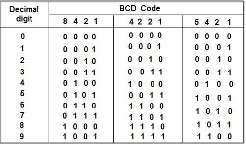
Let's look at several cases where we're converting decimal values to BCD.
The 8421 BCD code for 9.2 is 1001.0010.

The 4221 BCD code for 9.2 is 1111.0010.
The 5421 BCD code for 9.2 is 1100.0010.
BCD coding is useful for displaying information on displays that are always numeric (0–9), such as digital clocks and voltmeters.
Advantages
- It's a lot like the decimal system.
- Only the binary equivalents of decimal numerals 0 to 9 must be remembered.
Disadvantages
- The rules for adding and subtracting BCD are different.
- The math in BCD is a little more difficult.
- To express a decimal number in BCD, more bits are required than in binary. As a result, BCD is inefficient in comparison to binary.
EBCDIC
EBCDIC stands for extended binary coded decimal interchange code, and it has an eight-bit (or one-byte) width. This is a coding method for representing characters in digital text, such as letters, numbers, punctuation marks, and other symbols. In EBCDIC, a character is represented by eight bits. EBCDIC is a computer operating system that is mostly used on IBM mainframe and mid-range computers. Each byte is made up of two four-bit wide nibbles. The first four bits specify the character class, whereas the second specifies the exact character within that class.
EBCDIC is incompatible with the ASCII character set, which is used by all other computers. There are 256 distinct characters in the EBCDIC code. However, ASCII is the standard for personal computers. You can acquire a file conversion software that will convert between EBCDIC and ASCII if you wish to move text between your computer and a mainframe.
The character codes employed in IBM's per-electronic PUNCHED CARD devices were modified into EBCDIC, which rendered it less than optimal for current computers. The use of non-contiguous codes for alphabetic characters, as well as the omission of numerous punctuation marks, such as the square brackets [] utilised by much modern software, were among its many drawbacks.
Setting the first nibble to all-ones,1111, for example, specifies that the character is a number, whereas the second nibble specifies which number is encoded. Up to 256 distinct characters can be encoded using EBCDIC.
There have been at least six incompatible versions of EBCDIC, the most recent of which includes all ASCII characters but also includes characters that aren't supported by ASCII.
ASCII
The American Standard Code for Information Interchange (ASCII) is an acronym for American Standard Code for Information Interchange. A character collection of 128 7-bit characters that has been coded. The space character and the remove character are among the 32 control characters, 94 graphic characters, and the space character. The ASCII protocol consists of data encoded in ASCII values with just a few control codes. The printer interprets the control codes that are applied. ASCII communication is supported by all parallel, serial, and Ethernet mediums, and it is considered the industry standard.
Bits are tiny pieces of information that make up all data files. Each byte in an ASCII file corresponds to a particular character specified by the standard ASCII code. A text document produced without any formatting, such as font styles or paragraph indentations, is a common example of an ASCII file. A binary file containing ASCII codes is known as an ASCII file. There are 128 different ASCII codes, which means that an ASCII character can be represented with only 7 bits.
The American Standard Code for Information Interchange (ASCII) is an acronym for American Standard Code for Information Interchange. The ASCII code is an alphanumeric code used in digital computers to communicate data. ASCII is a 7-bit code that can represent a total of 27 or 128 distinct characters. The ASCII code consists of a three-bit group followed by a four-bit code.
Representation of ASCII
- The ASCII Code is an alphanumeric code that is 7 or 8 bits long.
- This code can be used to represent 127 different characters.
- From 00h to 7Fh, the ASCII code is used. Control characters are represented by the code from 00h to 1Fh, whereas graphic symbols are represented by the code from 20h to 7Fh.
- The 8-bit code contains ASCII, which may hold up to 256 symbols, including math and visual symbols.
- The extended ASCII ranges from 80h to FFh.
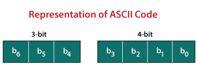
Below, you will find a table listing the standard ASCII codes, as used by computer programmers in the United States of America.
|
| ||||||||||||||||||||||||||||||||||||||||||||||||||||||||||||||||||||||||||||||||||||||||||||||||||||||||||||||||||||||||||||||||||||||||||||||||||||||||||||||||||||||||||||||||||||||||||||||||||||||||||||||||||||||||||||||||||||||||||||||||||||||||||||||||||||||||||||||||||||||||||||||||||||||||||||||||||||||||||||||||||||||||||||||||||||||||||||||||||||||||||||||||||||||||||||||||||||||||||||||||||||||||||||||||||||||||||||||||||||||||||||||||||||||||||||||||||||||||||||||||||||||||||||||||||||||||||||||||||||||||||||||||
Grey
The Gray Code, also known as reflected binary code, is a series of binary number systems. The initial N/2 values are compared to the last N/2 values in reverse order, which is why this code is called reflected binary code. Two successive values are separated by one bit of binary digits in this coding. In the general sequence of hardware-generated binary numerals, grey codes are employed. When transitioning from one number to the next, certain numbers might generate ambiguity or problems. When the transition between numbers is complete, this code simply addresses the problem by modifying only one bit.
Because it is not dependent on the value of the digit indicated by the location, the grey code is a very light weighted code.
How to generate grey code?
To generate the Gray code of a number, the prefix and reflect methods are applied recursively. To generate grey code, follow these steps:
- The amount of bits required to represent a number is determined.
- Then we look for the code for zero, which is 0000, which is the same as binary.
- Now we'll replace the most significant portion of the prior code, which is 0000.
- We carry doing this procedure in secret until all of the codes are unidentifiable.
- If changing the most significant bit yields the same result as changing the second most significant bit, the third most significant bit will be altered, and so on.
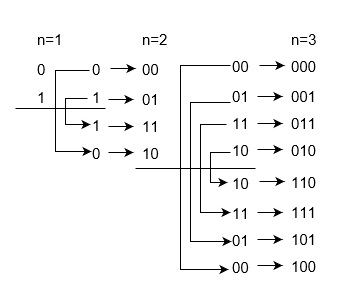
Grey code table
Decimal Number | Binary Number | Grey Code |
0 | 0000 | 0000 |
1 | 0001 | 0001 |
2 | 0010 | 0011 |
3 | 0011 | 0010 |
4 | 0100 | 0110 |
5 | 0101 | 0111 |
6 | 0110 | 0101 |
7 | 0111 | 0100 |
8 | 1000 | 1100 |
9 | 1001 | 1101 |
10 | 1010 | 1111 |
11 | 1011 | 1110 |
12 | 1100 | 1010 |
13 | 1101 | 1011 |
14 | 1110 | 1001 |
15 | 1111 | 1000 |
Key takeaway
The binary coded decimal (BCD) is a sort of binary code that is used to convert a decimal number to its binary equivalent.
EBCDIC stands for extended binary coded decimal interchange code, and it has an eight-bit (or one-byte) width.
The American Standard Code for Information Interchange (ASCII) is an acronym for American Standard Code for Information Interchange.
The Gray Code, also known as reflected binary code, is a series of binary number systems.
Excess-3 code
● It is also known as XS-3 code.
● It is a non-weighted code used to express decimal numbers.
● They are derived from the 8421 BCD code words adding (0011)2 or (3)10 to each code word in 8421.
● The excess-3 codes are obtained as −

Example
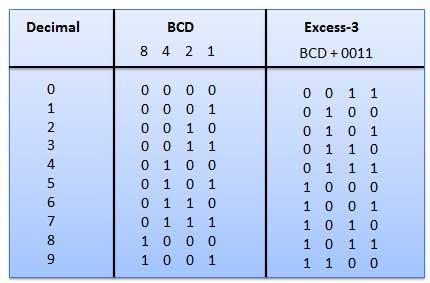
Fig: BCD to XS 3 conversion
Key takeaway
The binary coded decimal (BCD) is a sort of binary code that is used to convert a decimal number to its binary equivalent.
The American Standard Code for Information Interchange (ASCII) is an acronym for American Standard Code for Information Interchange.
The Gray Code, also known as reflected binary code, is a series of binary number systems.
Basic Input and Output Settings (BIOS)
BIOS (basic input/output system) is the program a computer's microprocessor uses to start the computer system after it is powered on. It also manages data flow between the computer's operating system (OS) and attached devices, such as the hard disk, video adapter, keyboard, mouse and printer.
History of BIOS
The term BIOS was first coined in 1975 by American computer scientist Gary Kildall. It was incorporated into IBM's first personal computer in 1981 and, in the years to come, gained popularity within other PCs, becoming an integral part of computers for some time. However, BIOS' popularity has waned in favour of a newer technology: Unified Extensible Firmware Interface (UEFI). Intel announced a plan in 2017 to retire support for legacy BIOS systems by 2020, replacing them with UEFI.
Uses of BIOS
The main use of BIOS is to act as a middleman between OSes and the hardware they run on. BIOS is theoretically always the intermediary between the microprocessor and I/O device control information and data flow. Although, in some cases, BIOS can arrange for data to flow directly to memory from devices, such as video cards, that require faster data flow to be effective.
How does BIOS work?
BIOS comes included with computers, as firmware on a chip on the motherboard. In contrast, an OS like Windows or iOS can either be pre-installed by the manufacturer or vendor or installed by the user. BIOS is a program that is made accessible to the microprocessor on an erasable programmable read-only memory (EPROM) chip. When users turn on their computer, the microprocessor passes control to the BIOS program, which is always located at the same place on EPROM.
When BIOS boots up a computer, it first determines whether all of the necessary attachments are in place and operational. Any piece of hardware containing files the computer needs to start is called a boot device. After testing and ensuring boot devices are functioning, BIOS loads the OS -- or key parts of it -- into the computer's random access memory (RAM) from a hard disk or diskette drive (the boot device).
The 4 functions of BIOS
BIOS identifies, configures, tests and connects computer hardware to the OS immediately after a computer is turned on. The combination of these steps is called the boot process.
These tasks are each carried out by BIOS' four main functions:
- Power-on self-test (POST). This tests the hardware of the computer before loading the OS.
- Bootstrap loader. This locates the OS.
- Software/drivers. This locates the software and drivers that interface with the OS once running.
- Complementary metal-oxide semiconductor (CMOS) setup. This is a configuration program that enable users to alter hardware and system settings. CMOS is the name of BIOS' non-volatile memory.
Accessing BIOS
With BIOS, the OS and its applications are freed from having to understand exact details, such as computer hardware addresses, about the attached I/O devices. When device details change, only the BIOS program needs to be changed. Sometimes, this change can be made during system setup.
Users can access BIOS and configure it through BIOS Setup Utility. Accessing BIOS Setup Utility varies somewhat depending on the computer being used. However, the following steps generally enable users to access and configure BIOS through Setup Utility:
● Reset or power off the computer.
● When the computer turns back on, look for a message that says "entering setup" or something similar. Accompanying that message will be a key that the user should press to enter system configuration. Here's an example message a user might see: "Press [key] to enter BIOS setup." Some keys often used as prompts are Del, Tab, Esc and any of the function keys (F1-F12).
● Upon seeing the prompt, quickly press the key specified.
Once in BIOS Setup Utility, users can change hardware settings, manage memory settings, change the boot order or boot device, and reset the BIOS password, among other configuration tasks.
BIOS security
BIOS security is a somewhat overlooked component of cybersecurity; however, it should still be managed to prevent hackers from executing malicious code on the OS. Security group Cylance, in 2017, showed how modern BIOS security flaws could enable ransomware programs inside a motherboard's UEFI and exploit other PC BIOS vulnerabilities.
Another unique exploit involving the manipulation of BIOS was Plundervolt. Plunder Volt could be used to mess with a computer's power supply at the time data was being written to memory, causing errors that lead to security gaps. Intel released a BIOS patch to defend against it.
BIOS manufacturers
BIOS, in its beginnings, was originally owned by IBM. However, some companies, such as Phoenix Technologies, have reverse-engineered IBM's original version to create their own. Phoenix, in doing this, allowed other companies to create clones of the IBM PC and, more importantly, create non-IBM computers that work with BIOS. One company that did this was Compaq.
Today, many manufacturers produce motherboards with BIOS chips in them. Some examples are the following:
● AMI
● Asus
● Foxconn
● Hewlett Packard (HP)
● Ricoh
Knowing the motherboard manufacturer is important because users may want to update their BIOS and chipset drivers -- the drivers that enable the OS to work with other devices in the computer, such as a video card -- to the most recent versions. Driver updates may improve computer performance or patch recent BIOS-level security vulnerabilities. Each manufacturer has a unique way of updating these drivers.
View BIOS information at POST
The first way is by restarting your computer. When the initial load (also called POST) screen is displayed, the BIOS Type and version is also displayed.
Tip
If the load screen is displayed for only a few seconds, you can try pressing the Pause/Break key on your keyboard to pause the loading process. Pausing the screen should make it easier to find and read the BIOS information. When you're ready to resume the boot process, press Pause/Break again.
The BIOS information is often found at or near the top of the POST screen.
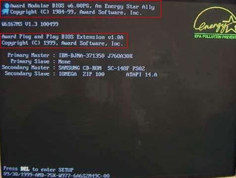
Also, you will see information on what hard drive(s) and CD/DVD drives are installed in your computer.
Tip
On the boot screen, you can also access the CMOS setup for more hardware.
● How to enter the BIOS or CMOS setup.
To help with load times, or display a company logo, this screen may not be viewable. If this is the case, try the below alternate resolutions.
Through Windows System Information
The BIOS information is also shown in the Windows System Information utility. To open this utility, click Start, Programs, Accessories, System Tools, and then System Information. If you're running Windows Vista or Windows 7, or Windows 10 type System Information in the Start search box.
The System Information window displays information about your computer, including the type of BIOS you have and the version, under the System Summary section. As seen in the picture below, this computer has a DELL BIOS version 1.0.0 with a BIOS Version/Date of 11/5/2008.
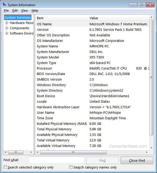
Using the system info command line command
You can also use the system info command from the command line to view the BIOS version and other system information by following the following steps.
- Open the Windows command line.
- Type system info and press Enter to get a screen similar to the example shown below.
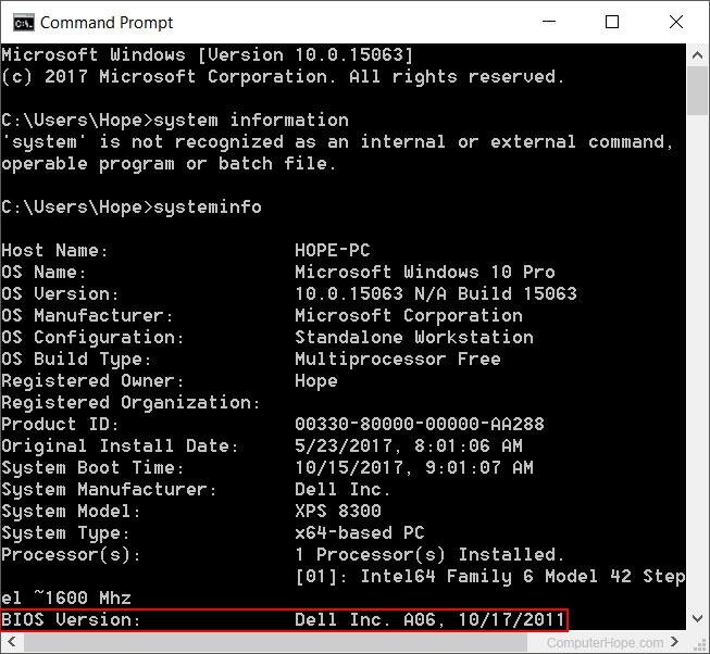
Note
You may need to scroll up to see the BIOS version.
In the Windows registry
You can also find BIOS information in the Windows registry. While in the registry, realize that improperly changing a setting can affect how Windows operates. So be careful if you choose to use this option to view your BIOS information.
To access the registry, click Start and in the Run or Search box, type regedit in the text field and press Enter. In the Registry Editor, navigate to the below registry directory.
HKEY_LOCAL_MACHINE\HARDWARE\DESCRIPTION\System
Find the subkeys SystemBiosDate and SystemBiosVersion to see the BIOS and version for your motherboard. As seen in the picture below, the BIOS date and version are shown in these two keys.
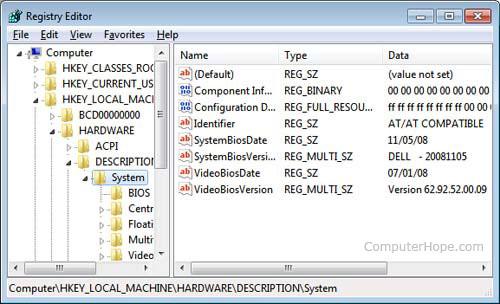
Finding BIOS date through debug routine
Earlier computers without access to the above tools can also use the MS-DOS and Windows command line debug command to view the BIOS date, as shown below.
At the C:\> prompt, type the following commands.
Debug
- d FFFF:5 L 8
After typing the above command, a string similar to the example below is shown.
FFFF:0000 30 34 2F-33 30 2F 39 38 4/30/98
The 4/30/98 would be the date of your computer BIOS.
Network Interface Card (NIC)
A network interface card (NIC) is a piece of hardware that allows a computer to connect to a network. It is a circuit board that is installed in a computer and provides the machine with a dedicated network connection. It's also known as a network adapter, network interface controller, or LAN adapter.
It connects various networking devices, such as computers and servers, in order to share data via a network. Support for I/O interrupts, Direct Memory Access (DMA) interfaces, partitioning, and data transmission are all included.
The NIC is required for us to establish a wired or wireless network connection.
Purpose
● Both cable and wireless communication are possible with the NIC.
● The network interface card (NIC) permits communication between computers linked via a local area network (LAN) as well as communication over a large-scale network using Internet Protocol (IP).
● A network interface card (NIC) is a physical layer and data link layer device that provides the essential hardware circuitry for physical layer and some data link layer activities to execute on it.
Types of NIC Cards
There are two types of NIC cards:
Internal Network Cards
Internal network cards have a slot on the motherboard into which they can be put. Network access necessitates the use of network cables. There are two types of internal network cards. The first uses a Peripheral Component Interconnect (PCI) connection, whereas the second uses an Industry Standard Architecture (ISA) connection (ISA).
External Network Cards
External NICs are utilised in desktops and laptops that do not have an internal NIC. There are two types of external network cards: wireless and USB-based. Although a wireless network card must be put into the motherboard, there is no requirement for a network cable to connect to the network. They can in handy whether travelling or trying to connect to a wireless network.
Advantages
● NIC delivers a more secure, faster, more stable connection than a wireless network card.
● We can share large amounts of data among numerous people thanks to NIC.
● It allows us to connect peripheral devices to multiple NIC ports.
● Communication is quite fast.
● Network Interface Cards are reasonably priced.
Troubleshooting NICs is simple.
Disadvantages
● In comparison to the wireless card, the NIC is inconvenient.
● A hard-wired connection is required for wired NIC.
● To function properly, the NIC must be configured properly.
● Because NIC cards are insecure, the data stored on them is also insecure.
Graphic Card
Graphics cards, often known as video cards, are computer cards that feature graphics processing units and specialised memory for storing video data. Dedicated GPUs can produce video and 3D graphics faster than a computer's central processor unit because they can process graphics data more efficiently. Graphics cards also improve graphics work in other ways, such as allowing for higher-quality renderings, enabling specific capabilities in design applications, and accelerating video encoding.
A graphics card is a piece of hardware that is used to boost a computer's video memory and improve its display quality. It increases the computer's power and allows it to perform higher-level tasks. The image quality is determined by the graphics card's capabilities. It is critical for gaming and video editing on a computer. To begin, every game requires graphics memory, which varies depending on the type of game and is specified on the game box.
Features of Graphics Card
● Memory – Each graphics card is equipped with its own memory. Memory sizes could range from 128MB to 2GB. We should purchase a memory card. Higher resolutions, more colours on the screen, and the best special effects all come with more RAM.
● Multiple Screen support – Most recent video cards can link two monitors to a single card. This functionality is essential for video editing, and dedicated gamers appreciate the extra space. You have the option of seeing two independent Desktops or combining the two monitors into one.
● Gaming And Video Editing – A separate graphics card is useful not just for gamers, but also for individuals who utilise high-end video editing software, since it reduces image rendering time and provides a high-definition environment.
Types of Graphic Cards
If you install a separate video card to your computer, the video and video games will run faster. However, there are many different types of graphics cards on the market; you should know which one is best for your computer.
On-Board
Most budget-based PCs come with an on-board graphics card rather than separate graphics cards because they include an expansion slot. The on-board graphics card is usually not powerful enough to decode high-quality video and play graphics-intensive games. On-board graphics are not physically removable. If you need to replace on-board graphics with an add-on graphics card, you must disable on-board graphics in the computer's BIOS first.
External Graphics Cards
Since laptop computer manufacturers no longer include space for an add-on graphics card, some firms have begun to offer external graphics cards to improve graphics capabilities.
AGP
AGP, which stands for Accelerated Graphics Port, was the standard graphics card type in the early to mid-2000s. These cards have been supplanted by PCI Express in recent years, and they are no longer commercially available. Furthermore, most hardware manufacturers do not provide AGP ports in their computers. ATI announced the Radeon HD 4000 series in 2008, however no additional cards have been produced since.
PCI Express
As of 2009, PCI Express is a standard in video cards. PCI Express graphics cards are only made by two companies: NVIDIA and ATI. It has three architectures, the most recent being PCI Express 3.0.
Key takeaway
BIOS (basic input/output system) is the program a computer's microprocessor uses to start the computer system after it is powered on.
A network interface card (NIC) is a piece of hardware that allows a computer to connect to a network.
Graphics cards, often known as video cards, are computer cards that feature graphics processing units and specialised memory for storing video data.
HTTP stands for Hypertext Transfer Protocol. It is a protocol used to access the data on the World Wide Web (www). The HTTP protocol can be used to transfer the data in the form of plain text, hypertext, audio, video, and so on. This protocol is known as Hypertext Transfer Protocol because of its efficiency that allows us to use it in a hypertext environment where there are rapid jumps from one document to another document.
HTTP is similar to the FTP as it also transfers the files from one host to another host. But HTTP is simpler than FTP as HTTP uses only one connection, i.e., no control connection to transfer the files. HTTP is used to carry the data in the form of MIME-like format. HTTP is similar to SMTP as the data is transferred between client and server. The HTTP differs from the SMTP in the way the messages are sent from the client to the server and from server to the client. SMTP messages are stored and forwarded while HTTP messages are delivered immediately.
Hypertext Transfer Protocol (HTTP) is an application layer protocol which enables WWW to work smoothly and effectively. It is based on a client-server model. The client is a web browser which communicates with the web server which hosts the website. This protocol defines how messages are formatted and transmitted and what actions the Web Server and browser should take in response to different commands. When you enter a URL in the browser, an HTTP command is sent to the Web server, and it transmits the requested Web Page.
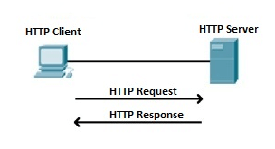
Fig 28: HTTP Request and Response
When we open a website using a browser, a connection to the web server is opened, and the browser communicates with the server through HTTP and sends a request. HTTP is carried over TCP/IP to communicate with the server. The server processes the browser's request and sends a response, and then the connection is closed. Thus, the browser retrieves content from the server for the user.
Features of HTTP
- Connectionless protocol: HTTP is a connectionless protocol. HTTP client initiates a request and waits for a response from the server. When the server receives the request, the server processes the request and sends back the response to the HTTP client after which the client disconnects the connection. The connection between client and server exists only during the current request and response time only.
- Media independent: HTTP protocol is a media independent as data can be sent as long as both the client and server know how to handle the data content. It is required for both the client and server to specify the content type in MIME-type header.
- Stateless: HTTP is a stateless protocol as both the client and server know each other only during the current request. Due to this nature of the protocol, both the client and server do not retain the information between various requests of the web pages.
HTTP Transactions
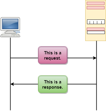
Fig 29: HTTP Transaction
The above figure shows the HTTP transaction between client and server. The client initiates a transaction by sending a request message to the server. The server replies to the request message by sending a response message.
Messages
HTTP messages are of two types: request and response. Both the message types follow the same message format.
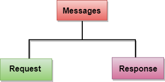
Fig 30: Message
Request Message: The request message is sent by the client that consists of a request line, headers, and sometimes a body.
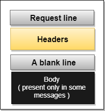
Fig 31: Request Message
Response Message: The response message is sent by the server to the client that consists of a status line, headers, and sometimes a body.
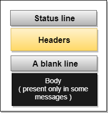
Fig 32: Response Message
Key takeaway
HTTP stands for Hypertext Transfer Protocol. It is a protocol used to access the data on the World Wide Web (www). The HTTP protocol can be used to transfer the data in the form of plain text, hypertext, audio, video, and so on.
FTP
● FTP stands for File transfer protocol.
● FTP is a standard internet protocol provided by TCP/IP used for transmitting the files from one host to another.
● It is mainly used for transferring the web page files from their creator to the computer that acts as a server for other computers on the internet.
● It is also used for downloading the files to computer from other servers.
Objectives of FTP
● It provides the sharing of files.
● It is used to encourage the use of remote computers.
● It transfers the data more reliably and efficiently.
Why FTP?
Although transferring files from one system to another is very simple and straightforward, but sometimes it can cause problems. For example, two systems may have different file conventions. Two systems may have different ways to represent text and data. Two systems may have different directory structures. FTP protocol overcomes these problems by establishing two connections between hosts. One connection is used for data transfer, and another connection is used for the control connection.
Mechanism of FTP
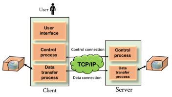
Fig 33: Mechanism of FTP
The above figure shows the basic model of the FTP. The FTP client has three components: the user interface, control process, and data transfer process. The server has two components: the server control process and the server data transfer process.
Types
There are two types of connections in FTP:
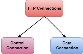
Fig 34: FTP Connections
● Control Connection: The control connection uses very simple rules for communication. Through control connection, we can transfer a line of command or line of response at a time. The control connection is made between the control processes. The control connection remains connected during the entire interactive FTP session.
● Data Connection: The Data Connection uses very complex rules as data types may vary. The data connection is made between data transfer processes. The data connection opens when a command comes for transferring the files and closes when the file is transferred.
FTP Clients
● FTP client is a program that implements a file transfer protocol which allows you to transfer files between two hosts on the internet.
● It allows a user to connect to a remote host and upload or download the files.
● It has a set of commands that we can use to connect to a host, transfer the files between you and your host and close the connection.
● The FTP program is also available as a built-in component in a Web browser. This GUI based FTP client makes the file transfer very easy and also does not require to remember the FTP commands.
Advantages of FTP:
● Speed: One of the biggest advantages of FTP is speed. The FTP is one of the fastest way to transfer the files from one computer to another computer.
● Efficient: It is more efficient as we do not need to complete all the operations to get the entire file.
● Security: To access the FTP server, we need to login with the username and password. Therefore, we can say that FTP is more secure.
● Back & forth movement: FTP allows us to transfer the files back and forth. Suppose you are a manager of the company, you send some information to all the employees, and they all send information back on the same server.
Disadvantages of FTP:
● The standard requirement of the industry is that all the FTP transmissions should be encrypted. However, not all the FTP providers are equal and not all the providers offer encryption. So, we will have to look out for the FTP providers that provides encryption.
● FTP serves two operations, i.e., to send and receive large files on a network. However, the size limit of the file is 2GB that can be sent. It also doesn't allow you to run simultaneous transfers to multiple receivers.
● Passwords and file contents are sent in clear text that allows unwanted eavesdropping. So, it is quite possible that attackers can carry out the brute force attack by trying to guess the FTP password.
● It is not compatible with every system.
Key takeaway
FTP stands for File transfer protocol. FTP is a standard internet protocol provided by TCP/IP used for transmitting the files from one host to another.
● The TCP/IP model was developed prior to the OSI model.
● The TCP/IP model is not exactly similar to the OSI model.
● The TCP/IP model consists of five layers: the application layer, transport layer, network layer, data link layer and physical layer.
● The first four layers provide physical standards, network interface, internetworking, and transport functions that correspond to the first four layers of the OSI model and these four layers are represented in TCP/IP model by a single layer called the application layer.
● TCP/IP is a hierarchical protocol made up of interactive modules, and each of them provides specific functionality.
Here, hierarchical means that each upper-layer protocol is supported by two or more lower-level protocols.
Functions of TCP/IP layers:
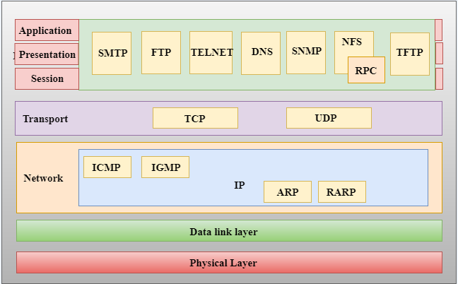
Fig 35: TCP/IP
Network Access Layer
● A network layer is the lowest layer of the TCP/IP model.
● A network layer is the combination of the Physical layer and Data Link layer defined in the OSI reference model.
● It defines how the data should be sent physically through the network.
● This layer is mainly responsible for the transmission of the data between two devices on the same network.
● The functions carried out by this layer are encapsulating the IP datagram into frames transmitted by the network and mapping of IP addresses into physical addresses.
● The protocols used by this layer are Ethernet, token ring, FDDI, X.25, frame relay.
Internet Layer
● An internet layer is the second layer of the TCP/IP model.
● An internet layer is also known as the network layer.
● The main responsibility of the internet layer is to send the packets from any network, and they arrive at the destination irrespective of the route they take.
Following are the protocols used in this layer are:
IP Protocol:
IP protocol is used in this layer, and it is the most significant part of the entire TCP/IP suite.
ARP Protocol
Following are the responsibilities of this protocol:
● IP Addressing: This protocol implements logical host addresses known as IP addresses. The IP addresses are used by the internet and higher layers to identify the device and to provide internetwork routing.
● Host-to-host communication: It determines the path through which the data is to be transmitted.
● Data Encapsulation and Formatting: An IP protocol accepts the data from the transport layer protocol. An IP protocol ensures that the data is sent and received securely; it encapsulates the data into message known as IP datagram.
● Fragmentation and Reassembly: The limit imposed on the size of the IP datagram by data link layer protocol is known as Maximum Transmission unit (MTU). If the size of IP datagram is greater than the MTU unit, then the IP protocol splits the datagram into smaller units so that they can travel over the local network. Fragmentation can be done by the sender or intermediate router. At the receiver side, all the fragments are reassembled to form an original message.
● Routing: When IP datagram is sent over the same local network such as LAN, MAN, WAN, it is known as direct delivery. When source and destination are on the distant network, then the IP datagram is sent indirectly. This can be accomplished by routing the IP datagram through various devices such as routers.
● ARP stands for Address Resolution Protocol.
● ARP is a network layer protocol which is used to find the physical address from the IP address.
● The two terms are mainly associated with the ARP Protocol:
- ARP request: When a sender wants to know the physical address of the device, it broadcasts the ARP request to the network.
- ARP reply: Every device attached to the network will accept the ARP request and process the request, but only recipient recognize the IP address and sends back its physical address in the form of ARP reply. The recipient adds the physical address both to its cache memory and to the datagram header
ICMP Protocol
● ICMP stands for Internet Control Message Protocol.
● It is a mechanism used by the hosts or routers to send notifications regarding datagram problems back to the sender.
● A datagram travels from router-to-router until it reaches its destination. If a router is unable to route the data because of some unusual conditions such as disabled links, a device is on fire or network congestion, then the ICMP protocol is used to inform the sender that the datagram is undeliverable.
● An ICMP protocol mainly uses two terms:
- ICMP Test: ICMP Test is used to test whether the destination is reachable or not.
- ICMP Reply: ICMP Reply is used to check whether the destination device is responding or not.
● The core responsibility of the ICMP protocol is to report the problems, not correct them. The responsibility of the correction lies with the sender.
● ICMP can send the messages only to the source, but not to the intermediate routers because the IP datagram carries the addresses of the source and destination but not of the router that it is passed to.
Key takeaway
The TCP/IP model was developed prior to the OSI model. The TCP/IP model is not exactly similar to the OSI model. The TCP/IP model consists of five layers: the application layer, transport layer, network layer, data link layer and physical layer.
References:
- Computer Today –Basandara
- Fundamentals of Computers --V. Rajaraman.
- Computer Fundamentals – By P .K Sinha