Unit-3
Time Domain Analysis
3.1.1 Unit step response of First and second order systems
The OLTF G(s) = 1/TS
CLTF c(s)/R(s) = 1/1+TS
CE: HTS = 0
S= -1/T
C(s) = R(s) [G(S)/1+G(s)]
C(s) = R(s)/1+TS
So, Calculating value of c(s), c(t) for different input
a) Unit Step:
R(t) = u(t)
R(s) = 1/s
C(s) = 1/s(1+ST)
1/s(1+ST) = A/s + o/1+TS
1/s(1+ST) = A/S + 0/1+TS
1= A(1+ST) + BS
AT +B =0
A = 1
B= -T
C(s) = 1/s + (-T)/1+TS
= 1+ (-T)/1-(-T)s = 1-I/n/1+ass+1/T =e-t/s
C(t) = [ 1-e-t/T]
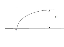
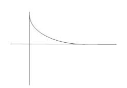
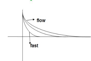
Fig 1 Output response for Unit Step input
b) Ramp:
For ramp input
R(t) = t
R(s) = 1/s2
C(s) = R(s) [G(s)/1+G(s)]
C(s) = 1/s2 1/(1+TS) + c
1/s2 (1+TS) = A/(s) + B/s2 + c(1+TS)
1 = A (s+s2. T) + B(1+TS) +cs2
TA +c = 0
A+TB =0
B =1
A = -T
C = T2
C(s) = -T/s + 1/s2 +T2/1+ST
=(-T) u(t) + t(u) + T e-t/T u(t)
= [ -T + t +Te-t/T u(t)
= [ -T+ t+Te-t/T] u(t)
C(s) = t- T+ Te-t/T
ess =  R(t) – c(t)
=  [ t- t+ 7-Te –t/T]
=  T( 1-e-t/T]
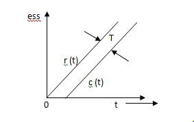 ess = The less the value of T the less in the errors.
Fig 2 Output response for ramp input
Key takeaway
1) From both the Cases input unit step, ramp Unit step
Unit Step Ramp
c(t) = 1-e-t/T r(t) = t
ess = e-t/T (r/t)-(t) c(t) = t- T+te-t/T
ess= e-t/T (r/t) (t) ess = T- Te-t/T
For :- for
 :-
:-
ess =0 ess = T
2) In both the vases (values of T) must be as small as possible (so, that e-t/T) must be as small as possible which gives us
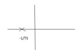
Fig 3 Location of poles
G(s) = 1/Ts
ATf = 1/1+TS
1st order system
Poles must be situated as far as possible from origin i.e. deeper and deeper into the left half of s-place. Thus, we get less errors.
Time response specifications
Specifications:
1) Rise Time (tp):- The time taken by the output to reach the already status value for the first time is known as Rise time.
C(t) = 1-e- wnt/
wnt/ 1-
1- 2 sin (wdt+ø)
Sin (wd +ø) = 0
Wdt +ø = n
tr =n -ø/wd
-ø/wd
For first time so ,n=1.


2) Peak Time (tp)
The peak value attained by the output is called peak time. The time required by the output to reach this value is lp.
d(cct) /dt = 0 (maxima)
d(t)/dt = peak value
tp = n /wd for n=1
tp =  wd
wd
3) Peak Overshoot Value:
Maximum deviation of output from steady state value is called peak overshoot value (Mp).
(ltp) = 1 = Mp
( Sin(Wat + φ )
( Sin( Wd∏/Wd + φ)
Mp = e-∏ξ / √1 –ξ2
Condition 3 ξ = 1
C( S ) = R( S ) Wn2 / S2 + 2ξWnS + Wn2
C( S ) = Wn2 / S(S2 + 2WnS + Wn2) [ R(S) = 1/S ]
C( S ) = Wn2 / S( S2 + Wn2 )
C( t ) = 1 – e-Wnt + tWne-Wnt
The response is critically damped.
(4). Settling Time (ts) :
ts = 3 / ξWn ( 5% )
ts = 4 / ξWn ( 2% )
Key takeaway
Rise Time tr =  -ø/wd
-ø/wd
Peak Time tp = n /wd for n=1
tp =  wd
wd
Peak Overshoot Value
Mp% = e-∏ξ / √1 –ξ2
Settling Time
ts = 3 / ξWn ( 5% )
ts = 4 / ξWn ( 2% )
3.1.2 Time response specifications of second order systems
OLTF G(s) = k/s(1+TS)
CLTF
C(s)/R(s) = k/k+s(1+Ts)
= k/s2+ s/T +k/T
 Comparing above equation with standard 2nd order eqn
Standard 2nd order equation
CEs2+2 wn s+wn2= 0
S= -2 wn±
wn± /2
/2
=2 wn±2wn
 /2
/2
S= wn±wn
wn±wn
S= - wn±wn
wn±wn
S= - wn ±wn
S= - wn ±gwn
Standard eqn:-
T(s) = wn2/s2+2 wns+wn2
Our eqn T(s) = K/T/s2+1/T s+ K/T
Wn2 = k/T
2 wn = 1/T
2 k/T = 1/T
 k/T = 1/2T
 = 1/2T
  T/K
T/K
 = 1
= 1 2KT
2KT
Graphically showing the position of loops s1,s2 for offered of
As the characteristic Equn (location of poles ) is dependent only on (wn constant for a given system)
S1 = - wn + jwn
  1-
1- 2
2
S2= - wn - jwn
 1-
1- 2
2
CASE 1: ( =0)
=0)
S1=jwn,S2, = -jwn
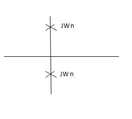
Fig 4 Location of poles for  =0
=0
Undamped
CASE 2:(0< <1)
<1)
S1= -wn + jwn  0.75
0.75
=-wn/2 +jwn(0.26)
S2 = -wn/2 – jwn (0.86)
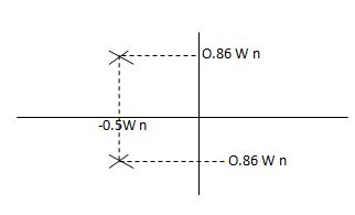
Fig 5 Location of poles for  <1
<1
CASE:3 ( =1)
=1)
S1= S2 = - wn = -wn
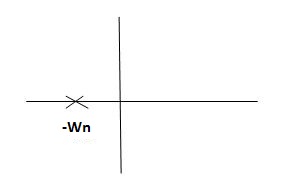
Fig 6 Location of poles for  =1
=1
CASE4:- ( =-2)
=-2)
S1 = -2wn +jwn  -3
-3
=-2wn – jwn (1.73)
S1 = -3.73wn
S2 = -2wn –jwn  -3
-3
= -2wn + jwn (1.73)
= -0.27  wn
wn
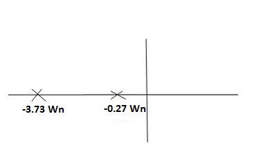
Fig 7 Location of poles for  >1
>1
Overdamped
CLTF = e(s)/ R(s) = wn2/s2+2 wns+wn2
Now calculating c(s) , c(t) for different values of input
1) Impulse I/p
R(t) =  (t)
(t)
R(s) = 1
C(s) = R(s) wn2/s2+2 wns+wn2
C(s) = wn2/s2 +2 wn+wn2
Under this i/p (R(t) =  (t)) the output varies with different values of
  . So,
. So,
CONDITION 1: ( =0)
=0)
C(s) =wn2/s2 +wn2
Os2 +wn2 =0
S=+-jwn
C(t) = wn sinwnt
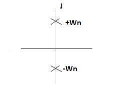
Sinwnt
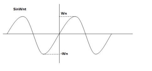
Fig 8 Undamped oscillations
As there in no damping i.e. oscillations at t= 0 are some at t  so, called UNDAMPED
CONDITION 2: 0<<1
c(s) = R(s) wn2/s22 wn+wn2 R(t) =
  (t)
(t)
R(s) =1
C(s) = wn2/s2+2 wns+wn2
CE
S2+2 wns +wn2 =0
S2, S1 = - wn ±jwn
  1-
1- 2
2
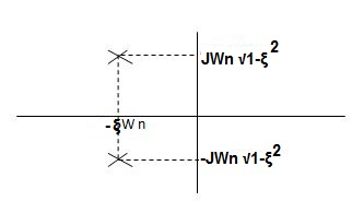
C(t) = e- wnt sin( wn
  )t
)t

C(t)=e- wnt sin (wdt)
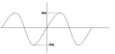
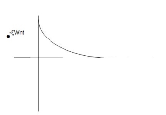
Fig 9 Underdamped oscillations
The oscillations are present but at t- infinity the Oscillations are 0 so, it is UNDERDAMPED
CONDITION 3 : =1
=1
C(s) = R(s) wn2/s2+2 wns+wn2
C(s)=wn2/S2 +2wns+wn2
=wn2/(s +wn)2
CE S= -Wn
C(t)= w2n /(
 )2
)2
C(t)=
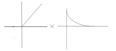
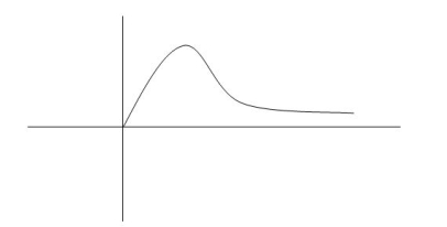
Fig 10 Critically damped oscillations
No damping obtained at  so is called CRITICALLY DAMPED.
CONDITIONS 4 :- >1
>1
C(s) = wn2/s22 wnS+Wn2
S1,s2 =  WN+-jwn
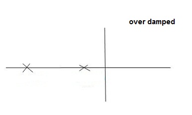
Fig 11 location of poles for over damped oscillations
c) UNIT Step Input:
R(s) = 1/s
C(s)/R(s) = wn2/s2+2 wns+wn2
C(s) = R(s) wn2 /s2 +2 wns+wn2
C(s) = R(s) wn2/s2+2 wns+wn2
C(s) = R(s) wn2/s2+2 wns+wn2
C(s) = wn2s(s2+2 wns+wn2)
C(t) = 1- e wnt/
wnt/ 1-es2 sin (wdt + ø)
Wd = wn 1-
1- 2
2
Ø= 
Where:
Wd = Damping frequency of oscillations
Wn = natural frequency of oscillations
 wn = damping coefficient.
T= Time constant
Condition 1 = 0
= 0
C(s) = wn2 /s(s2+wn2)
C(t) = 1- e° sin wdt +ø
C(t)= 1- sin( wn +90)
C(t) = 1+cos wnt
Constant
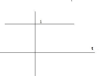

C(t) = 1+constant
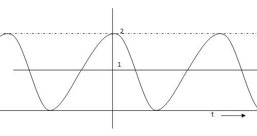
Fig 12 C(t) = 1+cos wnt
Condition 2:- 0< <1
<1
C(s) =  /s2+
/s2+ wns +wn2
C(s) =1/s – s+ wn/s2+
 wns +wn2
=1/s – s+ wn/(s+
 wn)2+wd2-
  wn/(s+
 wn2) +wd2
Wd = wn  1-
1- 2
2
Taking Laplace inverse of above equation
L --1 s+ wn/(s+
 wn) +wd2= e-
 wnt cos wdt
L-1 s+ wn/(s+
 wn)2+wd2 = e-
 wnt sinWdt
C(t) = 1-e- wnt [coswdt +
 /
/ 1-
1- 2 sinwdt]
= 1-e wnt /
wnt / 1-
1- 2 sin [wdt +
  1-
1- 2/
2/ ] t>=0
C(t) = 1-e wnt/
wnt/ 1-
1- 2 sin(wdt+ø)
Ø =  1+
1+ 2/
2/
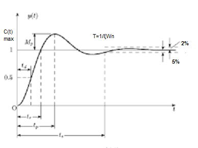
Fig 13 Transient Response of second order system
Key takeaway
All practical systems are 2 order to, if R(e) =  (t) R(s) = 1 :. CLTF = 2nd order standard eqn and hence already the system is possible.
Practice Problems
Q.1. The open loop transfer function of a system with unity feedback gain G( S ) = 20 / S2 + 5S + 4. Determine the ξ, Mp, tr, tp.
Soln : Finding closed loop transfer function,
C( S ) / R( S ) = G( S ) / 1 + G( S ) + H( S )
As it is unity feedback so, H(S) = 1
C(S)/R(S) = G(S)/1 + G(S)
= 20/S2 + 5S + 4/1 + 20/S2 + 5S + 4
C(S)/R(S) = 20/S2 + 5S + 24
Standard equation for second order system,
S2 + 2ξWnS + Wn2 = 0
We have,
S2 + 5S + 24 = 0
Wn2 = 24
Wn = 4.89 rad/sec
2ξWn = 5
(a). ξ = 5/2 x 4.89 = 0.511
(b). Mp% = e-∏ξ / √1 –ξ2 x 100
= e-∏ x 0.511 / √1 – (0.511)2 x 100
Mp% = 15.4%
(c). tr = ∏ - φ / Wd
φ = tan-1√1 – ξ2 / ξ
φ= tan-1√1 – (0.511)2 / (0.511)
φ = 1.03 rad.
tr = ∏ - 1.03/Wd
Wd = Wn√1 – ξ2
= 4.89 √1 – (0.511)2
Wd = 4.20 rad/sec
tr = ∏ - 1.03/4.20
tr = 502.34 msec
(d). tp = ∏/4.20 = 747.9 msec
Q.2. A second order system has Wn = 5 rad/sec and is ξ = 0.7 subjected to unit step input. Find (i) closed loop transfer function. (ii) Peak time (iii) Rise time (iv) Setteling time (v) Peak overshoot.
Soln: The closed loop transfer function is
C(S)/R(S) = Wn2 / S2 + 2ξWnS + Wn2
= (5)2 / S2 + 2 x 0.7 x S + (5)2
C(S)/R(S) = 25 / S2 + 7s + 25
(ii). tp = ∏ / Wd
Wd = Wn√1 - ξ2
= 5√1 – (0.7)2
= 3.571 sec
(iii). tr = ∏ - φ/Wd
φ= tan-1√1 – ξ2 / ξ = 0.795 rad
tr = ∏ - 0.795 / 3.571
tr = 0.657 sec
(iv). For 2% settling time
ts = 4 / ξWn = 4 / 0.7 x 5
ts = 1.143 sec
(v). Mp = e-∏ξ / √1 –ξ2 x 100
Mp = 4.59%
Q.3. The open loop transfer function of a unity feedback control system is given by
G(S) = K/S(1 + ST)
Calculate the value by which k should be multiplied so that damping ratio is increased from 0.2 to 0.4?
Soln: C(S)/R(S) = G(S) / 1 + G(S)H(S) H(S) = 1
C(S)/R(S) = K/S(1 + ST) / 1 + K/S(1 + ST)
C(S)/R(S) = K/S(1 + ST) + K
C(S)/R(S) = K/T / S2 + S/T + K/T
For second order system,
S2 + 2ξWnS + Wn2
2ξWn = 1/T
ξ = 1/2WnT
Wn2 = K/T
Wn =√K/T
ξ = 1 / 2√K/T T
ξ = 1 / 2 √KT
Forξ1 = 0.2, for ξ2 = 0.4
ξ1 = 1 / 2 √K1T
ξ2 = 1 / 2 √K2T
ξ1/ ξ2 = √K2/K1
K2/K1 = (0.2/0.4)2
K2/K1 = 1 / 4
K1 = 4K2
Q.4. Consider the transfer function C(S)/R(S) = Wn2 / S2 + 2ξWnS + Wn2
Find ξ, Wn so that the system responds to a step input with 5% overshoot and settling time of 4 sec?
Soln:
Mp = 5% = 0.05
Mp = e-∏ξ / √1 –ξ2
0.05 = e-∏ξ / √1 –ξ2
Cn 0.05 = - ∏ξ / √1 –ξ2
-2.99 = - ∏ξ / √1 –ξ2
8.97(1 – ξ2) = ξ2∏2
0.91 – 0.91 ξ2 = ξ2
0.91 = 1.91 ξ2
ξ2 = 0.69
(ii). ts = 4/ ξWn
4 = 4/ ξWn
Wn = 1/ ξ = 1/ 0.69
Wn = 1.45 rad/sec
So, for difficult input, less will be different Input still be
1) R(s) = unit step
2) R (s) = Ramp
3) R(s) = parabolic
1) R(s)= Unit step
R(t) = u(t)
R(s) = 1/s
Ess =  s[ R(s)/1+G(s)]
=  s[ys/1+G(s)]
ess=  1+1/1+G(s)
 =1/1+lt G(s) s- 0
(Position error coefficient)

2) R(s) = Ramp
R(t) = t
R(s) = 1/s2
ess=  s[ R(s)/1+G(s)]
=  s[ys2/1+G(s)]
=  1/s(1+G(S)
= 1/s+SG(s)
ess = l/s-0 SG (s)
 ess =
ess =  t L/SG (s)
 velocity errors coefficient
(3) Parabolic
R(t) = t2
R(s) =1/s3
Ess =  s[ R(s)/1+G(s)]
=  s(1/s3)/1+G(s)
=  1/s2+s2G(s)
 Ess =
Ess =  1/s2G(s)
Acceleration error coefficient

Input Error coefficient
(1) Unit step ess= 1/1+kv kv =  G(S)
G(S)
(2) Ramp ess= 1/kv kv =  sG(s)
sG(s)
(3) Parabolic ess = 1/ka ka =  s2 G(s)
Now finding errors in type 0,1,2 system
1) Type 0:-
G(s) = 1/(s+a) (s+b)
2) Kp :
Kp =
= 1/(s+a)(s+b)
Kp= 1/ab
Ess=1/1+np = 1/1+(1/ab) 
o/p not locking the input
(b) kv:-
Kv =  s G(s)
=  s/(s+a) (s+b)
= s/(s+a) (s+b)
Kv = 0
ess = 1/kv = 
o/p not locating the input
(3)ka:-
Ka =  s2 G(s)
=  s2 /(s+a) (s+b)
Ka =0
ess = 1/ka = 
o/p not locking the input
(2)Type –I :-
G(s) = 1/s(s+a) (s+b)
(a)Kp:-
Kp =  G(s)
G(s)
= 1/s(s2+as+ab)
Kp = 1/0 = 
ess = 1/1+kp = 0
o/p is tracking the input
(b)kv:-
Kv =  S G(s)
= 1/(s+a) (s+b)
=1/ab
Kv = 1/ab
ess =1/ka = ab 
o/p is not tracking the input
3)ka :
Ka=  s2G(s)
=  s2 /s(s+a)(s+b)
=  s/(s+a)(s+b)
Ka= 0
Ess = 1/ka = 
O/p is not tracking the input .
3) Type 2 :-
G(s) = 1+/(s2(s+a) (s+b)
a) Kp:-
Kp =  G(s)
G(s)
=  1/s2 (s+a) (s+b)
Kp = 
ess = 1/1+kp = 0
o/p tracking the i/p
b) kv:-
Kv = s G(s)
= 1/s(s+a) (1+b)
kv = 
ess =1/ = 0
= 0
o/p tracking the o/p
(b) ka:-
Ka=  s2G(s)
= 1/(s+a) (s+b)
Ka = 1/ab
ess = 1/(ab) ≠0
o/p not locking the i/p
Key takeaway:
|
Unit step ≠0 0 0 |
Ramp  |
Parabolic  |
The root locus is a graphical produce for determining the stability of a control system which is determined by the location of the poles. The poles are nothing but the roots of the characteristic equation.
The root locus concepts
Features of Root Locus
- It is symmetrical to the real axis.
- Number of branches of root locus is equal to number of max (poles or zero).
- Starting point (k=0) End point(k—>∞)
(open loop poles) (open loop zeros)
4. A point on the real axis lies on the root locus if number of open loop poles or zero to the right side of that point is odd in number.
5. Value of K anywhere on the root locus is given as
K = 
6. I)If poles > zeros then (Þ-z) branches will terminate at ∞ (where k=∞)
II)If Z > P, then (Z-P) branches will start from ∞ (K = 0)
7. When P>Z, (P-Z) branches will terminate at ∞ (open loop zeros). But by which path. So the path is shown by asymptotes and this asymptotes is given by
Asymptote =  q = o,1,2……(P-Z-1)
8. There asymptotes intersect the real axis at a single point and this point is known as centroid.
Centroid = 
9. Break away and break in point when root locus lie between two poles its called break in point.
Centroid and Breakaway points are not same
Differentials the characteristic equation and equate to zero 
10. Angle of arrival and angle of departure this print is used when the roots are complex.
Angle of departure - for complex poles
Angle of arrival – for complex zero.
 øD =(2q+1) 180° + ø
øA = (2q+1) 180° - ø ø = ∠Z– ∠P.
11. Intersection of root locus with imaginary axis can be calculated by Routh Hurwitz. By calculating valve of k at intersection point (we can comment about system stability) so by knowing values of k at intersection point (imaginary axis) the valve of s at that point can also be calculated.
Absolutely stable: If the root low (all the branches) lies within the left side of S-plane.
Conditionally Stable:- If some part of the root locus lies on the left half and same
Part on the right of S-plane then it is conditionally stable.
Unstable: If the root locus lies completely on right side of S-plane then it is unstable.
Key takeaway
The values of S which satisfy both the angle and magnitude conditions are the roots of the characteristic equation.
Angle condition:
LG(S)H(S) = +-1800(2 KH) (K = 1,2,3,--)
If angle is odd multiple of 1800 it satisfies above condition.
Magnitude condition:
| G(S)H(S) = 1 | at any point on root locus. The magnitude condition can be applied only if angle condition is satisfied.
Construction of root loci.
Q1. Sketch the root locus for given open loop transfer function G(S) =  .
.
Soln:1) G(s) = 
Number of Zeros = 0
Number of polls S = (0, -1+j, -1-j) = (3).
1) Number of Branches = max (P, Z) = max (3, 0) = 3.
2) As there are no zeros in the system so, all branches terminate at infinity.
3) As P>Z, branches terminate at infinity through the path shown by asymptotes
Asymptote =  × 180° q = 0, 1, 2………..(p-z-1)
P=3, Z=0.
q= 0, 1, 2.
For q=0
Asymptote = 1/3 × 180° = 60°
For q=1
Asymptote =  × 180°
= 180°
For q=2
Asymptote =  × 180° = 300°
Asymptotes = 60°,180°,300°.
4) Asymptote intersects real axis at centroid
Centroid =
= 
Centroid = -0.66
5) As poles are complex so angle of departure
øD = (2q+1)×180°+ø
ø = ∠Z –∠P.
Calculating ø for S=0
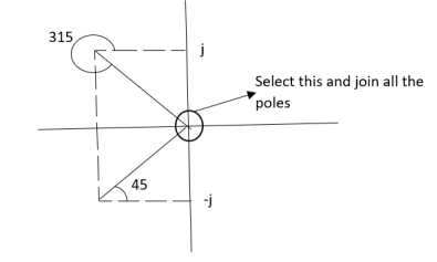
Join all the other poles with S=0
ø = ∠Z –∠P.
= 0-(315°+45°)
= -360°
ØD = (2q + 1)180 + ø.
= 180° - 360°
ØD = -180° (for q=0)
= 180° (for q=1)
=540° (for q=2)
Calculation ØD for pole at (-1+j)
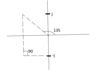
ø = ∠Z –∠P.
= 0 –(135°+90°)
= -225°
ØD = (2q+1) 180°+ø.
= 180-225°
= -45°
ØD = -45° (for q = 0)
= 315° (for q = 1)
= 675° (for q =2)
6) The crossing point on imaginary axis can be calculated by Routh Hurwitz the characteristic equation is.
1+G(s) H (s) = 0
1+
S (S2+2s+2)+k = 0
S3+2s2+2s+K = 0

S3 | 1 | 1 | 0 |
S2 | 2 | K | 0 |
S1 |  | 0 |
|
S0 | K |
|
|
|
|
|
|
For stability  > 0. And K > 0.
0<K<2.
So, when K=2 root locus crosses imaginary axis
S3 + 2S2 + 2S + 2 =0
For k
Sn-1 = 0 n : no. Of intersection
S2-1 = 0 at imaginary axis
S1 = 0
 = 0
= 0
K<4
For Sn = 0 for valve of S at that K
S2 = 0
2S2 + K = 0
2S2 + 2 = 0
2(S2 +1) = 0
32 = -2
S = ± j 
The root locus plot is shown in figure 1.
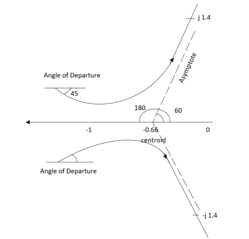
Fig 1 Root Locus for G(S) = 
Q2. Sketch the root locus plot for the following open loop transfer function
G(s) = 
- Number of zero = 0, number of poles = 3
- As P>Z, branches will terminates at infinity
- There are no zeros so all branches will terminate at infinity.
- The path for the branches is shown by asymptote
Asymptote =  ×180°. q=0,1,………p-z-1
P=3, Z=0
q= 0,1,2.
For q = 0
Asymptote =  × 180° = 60.
For q=1
Asymptote =  × 180° = 180°
For q=2
Asymptote =  × 180° = 300°
5. Asymptote intersect real axis at centroid
Centroid = 
=  = -1
= -1
6. As root locus lies between poles S= 0, and S= -1
So, calculating breakaway point.
 = 0
= 0
The characteristic equation is
1+ G(s) H (s) = 0.
1+  = 0
= 0
K = -(S3+3S2+2s)
 = 3S2+6s+2 = 0
3s2+6s+2 = 0
S = -0.423, -1.577.
So, breakaway point is at S=-0.423
Because root locus is between S= 0 and S= -1
7. The intersection of root locus with imaginary axis is given by Routh criterion.
Characteristics equation is
S3+3S3+2s+K = 0
| 1 | 2 |
S2 | 3 | K |
S1 |  | 0 |
S0 | K |
|
For k
Sn-1= 0 n: no. Of intersection with imaginary axis
n=2
S1 = 0
 = 0
= 0
K < 6 Valve of S at the above valve of K
Sn = 0
S2 = 0
3S2 + K =0
3S2 +6 = 0
S2 + 2 = 0
S = ±  j
j
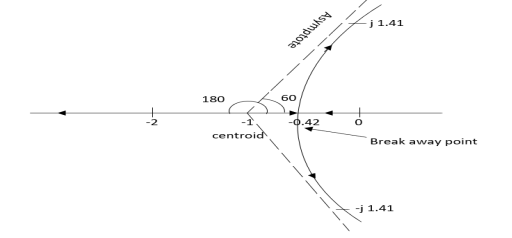
Fig 2 Root Locus for G(s) = 
The root locus plot is shown in fig. 2.
Q3. Plot the root locus for the given open loop transfer function
G(s) = 
- Number of zeros = 0 number of poles = 4
P = (S=0,-1,-1+j,-1-j) = 4
2. As P>Z all the branches will terminated at infinity.
3. As no zeros so all branches terminate at infinity.
4. The path for branches is shown by asymptote.
Asymptote =  q = 0,1,…..(Þ-z-1)
q=0,1,2,3. (P-Z = 4-0)
For q=0
Asymptote =  ×180° =45°
For q=1
Asymptote =  ×180° =135°
For q=2
Asymptote =  ×180° =225°
For q=3
Asymptote =  ×180° =315°
5. Asymptote intersects real axis at unmarried
Centroid = 
Centroid =  =
=  = -0.75
6) As poles are complex so angle of departure is
ØD = (2q+1) ×180 + ø ø = ∠Z –∠P.
A) Calculating Ø for S=0
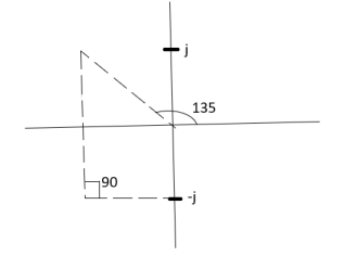
ø = ∠Z –∠P.
= 0 –[315° + 45°]
Ø = -360°
For q = 0
ØD = (2q+1) 180° + Ø
= 180 - 360°
ØD = -180°
b) Calculating Ø for S=-1+j
ø = ∠Z –∠P.
= 0-[135° + 90° + 90°]
Ø = -315°
For q=0
ØD= (2q+1) 180° +Ø
= 180° -315°
ØD = -135°
ØD for S=1+j will be ØD = 45°
7) As the root locus lie between S=0 and S=-1
So, the breakaway point is calculated

1+ G(s)H(s) = 0
1+  = 0
= 0
(S2+S)(S2 +2S+2) + K =0
K = -[S4+S3+2s3+2s2+2s2+2s]
 = 4S3+9S2+8S+2=0
S = -0.39, -0.93, -0.93.
The breakaway point is at S = -0.39 as root locus exists between S= 0 and S=-1
8) Intersection of root locus with imaginary axis is given by Routh Hurwitz
I + G(s) H(s) = 0
K+S4+3S3+4S2+2S=0

S4 | 1 | 4 | K |
S3 | 3 | 2 |
|
S2 | 3.33 | K |
|
S1 |  |
|
|
S0 | K |
|
|
For system to be stable
 >0
>0
6.66>3K
0<K<2.22.
For K = 2.22
3.3352+K =0
3.3352 + 2.22 = 0
S2 = -0.66
S = ± j 0.816.
The root locus plot is shown in figure 3.
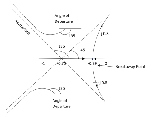
Fig 3 Root Locus for G(s) = 
Q4. Plot the root locus for open loop system
G(s) = 
1) Number of zero = 0 number of poles = 4 located at S=0, -2, -1+j, -1-j.
2) As no zeros are present so all branches terminated at infinity.
3) As P>Z, the path for branches is shown by asymptote
Asymptote = 
q = 0,1,2……p-z-1
For q = 0
Asymptote = 45°
q=1
Asymptote = 135°
q=2
Asymptote = 225°
q=3
Asymptote = 315°
4) Asymptote intersects real axis at centroid.
Centroid = 
= 
Centroid = -1.
5) As poles are complex so angle of departure is
ØD=(2q+1)180° + Ø
ø = ∠Z –∠P
= 0-[135°+45°+90°]
= 180°- 270°
ØD = -90°
6) As root locus lies between two poles so calculating point. The characteristic equation is
1+ G(s)H(s) = 0
1+ = 0.
= 0.
K = -[S4+2S3+2S2+2S3+4S2+4S]
K = -[S4+4S3+6S2+4S]
 = 0
= 0
 = 4s3+12s2+12s+4=0
S = -1
So, breakaway point is at S = -1
7) Intersection of root locus with imaginary axis is given by Routh Hurwitz.
S4+4S3+6S2+4s+K = 0

S4 | 1 | 6 | K |
S3 | 4 | 4 |
|
S2 | 5 | K |
|
S1 |  |
|
|
S0 | K |
|
|
 ≤ 0
≤ 0
K≤5.
For K=5 valve of S will be.
5S2+K = 0
5S2+5 = 0
S2 +1 = 0
S2 = -1
S = ±j.
The root locus is shown in figure 4.
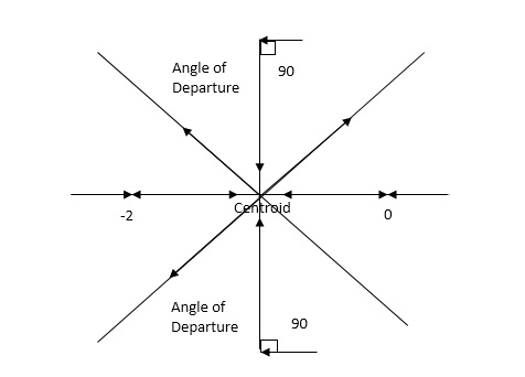
Fig 4 Root Locus For G(s) = 
Q5. Plot the root locus for open loop transfer function G(s) = 
- Number of zeros = 0. Number of poles = 4 located at S=0, -3, -1+j, -1-j.
- As no. Zero so all branches terminate at infinity.
- The asymptote shows the both to the branches terminating at infinity.
Asymptote =  q=0,1,….(p-z).
For q = 0
Asymptote = 45
For q = 1
Asymptote = 135
For q = 2
Asymptote = 225
For q = 3
Asymptote = 315
(4). The asymptote intersects real axis at centroid.
Centroid = ∑Real part of poles - ∑Real part of zero / P – Z
= [-3-1-1] – 0 / 4 – 0
Centroid = -1.25
(5). As poles are complex so angle of departure
φD = (29 + 1)180 + φ
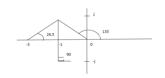
ø = ∠Z –∠P.
= 0 – [ 135 + 26.5 + 90 ]
= -251.56
For q = 0
φD = (29 + 1)180 + φ
= 180 – 215.5
φD = - 71.56
(6). Break away point dk / ds = 0 is at S = -2.28.
(7). The intersection of root locus on imaginary axis is given by Routh Hurwitz.
1 + G(S)H(S) = 0
K + S4 + 3S3 + 2S3 + 6S2 + 2S2 + 6S = 0
S4 1 8 K
S3 5 6
S2 34/5 K
S1 40.8 – 5K/6.8
K ≤ 8.16
For K = 8.16 value of S will be
6.8 S2 + K = 0
6.8 S2 + 8.16 = 0
S2 = - 1.2
S = ± j1.09
The plot is shown in figure 20.
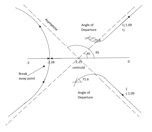
Fig 5 Root Locus for G(s) = 
Q.6. Sketch the root locus for open loop transfer function.
G(S) = K(S + 6)/S(S + 4)
- Number of zeros = 1(S = -6)
Number of poles = 2(S = 0, -4)
2. As P > Z one branch will terminate at infinity and the other at S = -6.
3. For Break away and breaking point
1 + G(S)H(S) = 0
1 + K(S + 6)/S(S + 4) = 0
Dk/ds = 0
S2 + 12S + 24 = 0
S = -9.5, -2.5
Breakaway point is at -2.5 and Break in point is at -9.5.
4. Root locus will be in the form of a circle. So finding the centre and radius. Let S = + jw.
G( + jw) = K( + jw + 6)/( + jw)( + jw + 4 ) = +- π
Tan-1 w/ + 6 - tan-1 w/ – tan-1 w / + 4 = - π
Taking tan of both sides.
w/ + w/ + 4 / 1 – w/ w/ + 4 = tan π + w / + 6 / 1 - tan π w/ + 6
w/ + w/ + 4 = w/ + 6[ 1 – w2 / ( + 4) ]
(2 + 4)( + 6) = (2 + 4 – w2)
2 2 + 12 + 4 + 24 = 2 + 4 – w2
22 + 12 + 24 = 2 – w2
2 + 12 – w2 + 24 = 0
Adding 36 on both sides
( + 6)2 + (w + 0)2 = 12
The above equation shows circle with radius 3.46 and centre (-6, 0) the plot is shown in figure 6
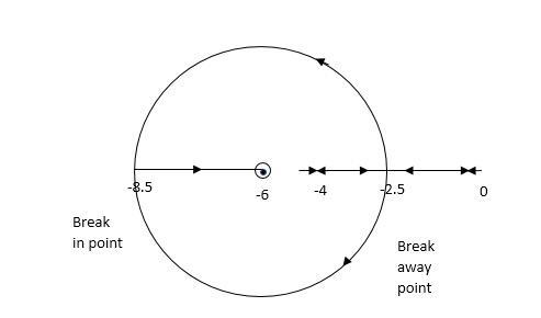
Fig 6 Root locus for G(S) = K (S + 6)/S (S + 4)
Root Locus analysis is useful for you to check the places where the poles of your linear system will be located on when you close its feedback loop with a gain factor. When you change the gain, the poles change their place through the loci.
If you have a simple SISO LTI system with its Transfer Function:
Y(s)=G(s)U(s)
Where,
G(s)=N(s)/D(s)
When you close the loop with a feedback gain, you’ll get
Y(s)=[G(s)/1+kG(s)]U(s)
=[N(s)/D(s)+kN(s)]U(s)
Without mathematical rigor, observe that if k→0k→0, the poles of the two systems are almost equal. It means that the poles are near from the original ones. But if k→∞⇒D(s)≪kN(s)k→∞⇒D(s)≪kN(s), and the poles approximate to the zeroes.
The most important is that if the loci go through the right-half plane, the system can become unstable for some gain values - those which place poles there.
Reference
1 A. Ananadkumar, “Control system Engineering” PHI publication 2nd edition.
2 R. Anandanatarajan, P. Ramesh Babu , “Control Systems Engineering”, Scitech Publications .
3 John R. Hackworth,Fredrick D. Hackworth “ Programmable Logic Controller” Pearson publication.
4 I.J. Nagrath, M.Gopal “Control Systems Engineering”, 5th Edition, New Age International


