Unit-6
Compensators & controllers
For getting the required performance we need to adjust the design parameters and this is called compensation. To achieve the required output parameters a device called compensator is used. The compensators are mainly used to increase the steady state accuracy of system. These compensators minimise the overshoot. As these compensators are introduced in the system the transfer function changes and hence the performance specifications also change.
Phase – Lead Compensation:
The phase of output voltage leads the phase of input voltage for the applied sinusoidal input. The circuit diagram is shown below. The transfer function is given as,
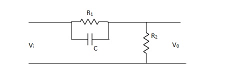
Fig 1 Phase Lead Compensation
Vo/Vi = α(1 + ST)/(1 + S α T)
Where, α = R2/R1 + R2 and α< 1
T = R1C
w = 1/T lower corner frequency due to zero.
w = 1/ αT upper corner frequency due to pole.
Mid frequency is given as,
wm = 1/T√ α
The maximum phase lead angle is φm
Φm = tan-1(1- α)/2√α = Sin-11- α/1 + α
Phase Lag Compensation:
The phase of the output voltage lags the phase of the input voltage for applied sinusoidal input. The circuit diagram is shown below,
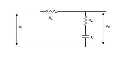
Fig 2 Phase Lag Compensation
Vo/Vi = 1 + ST/1 + SβT
Where, β = R1 + R2/R2, β> 1
T = R2C
w = 1/T upper corner frequency due to zero
w= 1/βT lower corner frequency due to pole
The mid frequency wm,
wm = 1/T√β
The maximum phase lead angle Φm
Φm = tan-11- β/2 √β
= sin-11 – β/1 + β
Phase Lag-Lead Network:
To overcome the disadvantages of lead and lag compensation, they are used together. As lead compensation does not provide phase margin but has fast response and lag compensation stabilize the system but does not provide enough bandwidth.
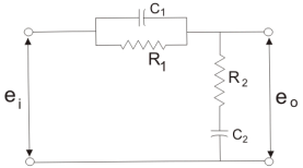
Fig 3 Lag-Lead Compensation
eo/ei = (1 + α ST1)/(1 + S T2)
T2)
Where, αT1 = R1C1
 T2= R2C2
We can say in the lag-lead compensation pole is more dominating than the zero and because of this lag-lead network may introduces positive phase angle to the system when connected in series.
Key takeaway
Phase Lead Network Phase Lag Network
1>. It is used to improve the 1>It is used to improve the
Transient response. Steady state response.
2>. It acts as a high pass filter. 2>It acts as a low pass filter.
3>. The system becomes fast as 3>The Bandwidth decreases
Bandwidth increases as rise through rise time the speed
Time decreases. is slow.
4>. As the circuit acts as 4>Signal to noise ratio is higher as it a differentiator, signal to acts as integrator.
Noise ratio is poor.
5>. Maximum peak overshoot 5>It reduces steady state error thus
Is reduced. improve the steady state accuracy
The controller is required when the system is unstable and the compensation will stabilize the system to improve its performance. There is one more situation when we require compensation that is when system is stable but not giving the proper performance. The type-2 or higher systems are mostly unstable and require lead compensator so that the stability of such systems can be increased. The techniques are discussed in detail below.
6.5.1 Basic ON-OFF Controller
The elements which are used to control only two positions either ON or OFF are called as ON-OFF controllers. They do not operate for any other value. In this kind of system, the output will change in process variable. As the output is affected the process variable again changes in reverse direction and at this stage when the process variable exceeds certain limits the output is closed. As the output is closed the process variable will again change in its normal direction and when the pre-set level is crossed the output is open. This process continues making the valve ON-OFF. These are mainly used in electrical power transformer for cooling purpose.
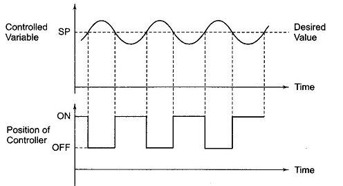
Fig 4 ON-OFF controller
The fan used for cooling the transformer uses these controllers. When the temperature (process variable) is more than the preset value the fan is turned ON and when temperature comes below the preset value the fan is turned OFF. In practical application there is a time lag in the switching of the circuit from ON to OFF and this is defined as dead time. This dead time or delay changes the actual curve of the system.
Key takeaway
The ON-OFF controller never works on any intermediate stage it will be either on or completely off.
6.5.2. Proportional (P) Controller
Effects of controller are viewed on time response and stability.
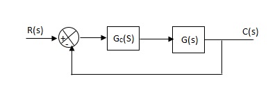
Fig 5 Controller with unity feedback system
Gc(S) = TF of the controller
G(S) = OLTF without controller
G’(S) = Gc(S).G(S)
= OLTF with controller
Proportional means scalar Multiplier.
Gc(S) = Kp Stability can be controlled
Que) G(S) = 1/S(S + 8)
CLTF = 1/S2 + 8S + 1
w2n = 1
wn = 1
2ξWn = 8
ξ = 4
ξ>/1 so, overdamped.
Now introducing Gc(S) = K
G’(S) = Kp/S(S + 8)
CLTF = Kp/S2 + 8S + Kp
wn = √Kp
2 ξwn = 8
ξ = 4/√Kp
If,
Kp = 16; ξ = 1; critically damped
Kp> 16; ξ< 1; undamped
Kp< 16; ξ> 1; overdamped
6.5.3 Integral (I) controller
The transfer function of this controller is
Gc(S) = Ki/S
Integral controller is used to improve the steady state response or reduce the steady state error.
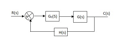
Fig 6 Integral Controller
G’(S) = Gc(S).G(S)
G(S) = 1/S + 5, Gc(S) = Ki/S
G’(S) = Ki/S(S + 5). After applying the Gc(S) the type of system is increasing and hence, the steady state error is decreasing (Refer Time Response).
Disadvantage -
By using integral controller, the stability of closed loop system decreases.
G(S) = 1/S + 5
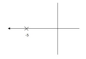
Fig 7 Pole Locations For given system
G’(S) = Ki/S(S + 5)
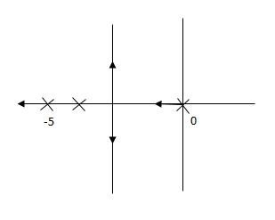
Fig 8 Pole Location after Integral controller
Fig(7), is more stable than (8) as more the away the pole from origin (imaginary axis) more is the stability.
Que. G(S) = 1/(S + 5)(S + 10)
G’(S) = Kp/S(S + 5)(S + 10)
G(S) = 1/(S + 5)(S + 10)
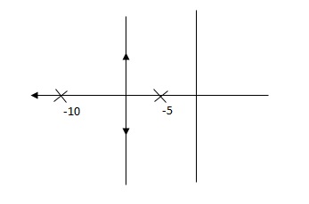
Fig 9 Root Locus Without controller
G’(S) = Ki/S(S + 5)(S + 10)
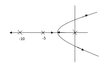
Fig 11 Root Locus Without controller
So, Fig 11 is less stable at root locus lies on the R.H.S,
6.5.4 Derivative (D) Controller -
Gc(S) = Kd(S)
They are used to improve the stability.
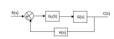
Fig 12 Derivative controller system
G’(S) = KdS/S2(S + 10)
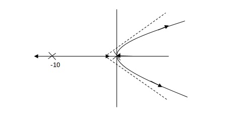
Fig 13 Root Locus for system without controller
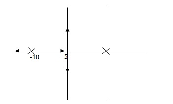
Fig 14 Root locus with controller
Fig 14 is stable i.e more stable than the Fig 13.
Disadvantage –
It increases the steady state i.e. o/p will not track the input at steady state.
6.5.5. Proportional Plus Integral [PI] controller -
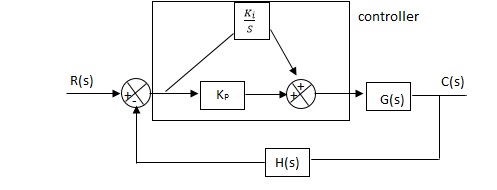
Fig 15 PI controller
Gc(S) = KpS + Ki/S
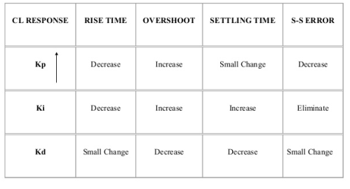
The steady state error will decrease and the stability will depend on Kp i.e. if Kp is increased/decreased than according to it stability will change (Kpα stability).
Used to reduce ess without much affecting the stability.
6.5.6. Proportional Plus Derivative (PD) Controller -
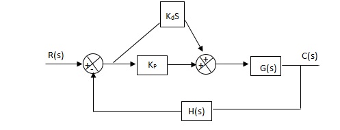
Fig 16 PD controller
Used to improve the stability without affecting much the steady state error.
6.5.7. PID controller
Gc(S) = Kp + Ki/S + KdS
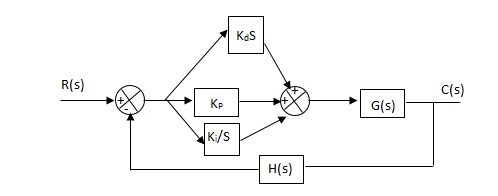
Fig 17 PID Controller
It improves the stability. It decreases the steady state error and both are proportional to Kp.
Key takeaway
Que) The block diagram of a system using PI controllers is shown in the figure 18 Calculate:
(a). The steady state without and with controller for unit step input?
(b). Determine TF of newly constructed sys. With controller so, that a CL Poles is located at -5?

Fig 18 Block diagram with PI controller
(a). Without :
C(S)/R(S) = 0.2/(S + 1)
C(S) = R(S) 0.2/(S + 1) + 0.2
For unit step
Ess = 1/1 + Kp
Kp = lt G(S)
S 0
= lt 0.2/(S + 1)
S 0
Kp = 0.2
Ess = 1/1.2 = 5/6 = 0.8
(b). With controller :
Gc(S) = Kp + Ki/S
G’(S) = Gc(S).G(S)
= ( Kp + Ki/S )0.2/(S + 1)
= (KpS + Ki)0.2/S(S + 1)
Ess = 1/1 + Kp = 0
So, the value of ess is decreased.
(b). Given
Kpi/Kp = 0.1
G’(S) = (Kp + Ki/S)(0.2/S + 1)
= (KpS + Ki)0.2/S(S + 1)
As a pole is to be added so, we have to examine the CE,
1 + G’(S) = 0
1 + (Kp + Ki)0.2/S(S + 1) = 0
S2 + S + 0.2KpS + 0.2Ki = 0
S2 + (0.2Kp + 1)S + 0.2Ki = 0
Given,
Kpi = 0.1Ki
Kp = 10Ki
S2 + (2Ki + 1)S + 0.2Ki = 0
Pole at S = -5
25 + (2Ki + 1)(-5) + 0.2Ki = 0
-10Ki – 5 + 25 + 0.2Ki = 0
-9.8Ki = -20
Ki = 2.05
Kp = 10Ki
= 20.5
Now,
G’(S) = (KpS + Ki)(0.2)/S(S + 1)
= (20.5S + 2.05)(0.2)/S(S + 1)
G’(S) = 4.1S + 0.41/S(S + 1)
Que. The block diagram of a system using Pd controller is shown, the PD is used to increase ξ to 0.8. Determine the T.F of controller?

Fig 19 Block diagram with PD controller
(1). Kp = 1
Without controller:-
C(S)/R(S) = 16/S2 + 1.6S + 16
wn = 4
2 ξwn = 16
ξ = 1.6/2 x 4 = 0.2
(b). With derivative :-
ξS = 0.2 to 0.8
Undamped to critically damped,
G’(S) = (1 + KdS)(16)/(S2 + 1.6S)
CE:
S2 + 1.6S + 16(1 + KdS) = 0
S2 + (1.6 + Kd)S + 16 = 0
2 ξwn = 1.6 + Kd1.6
wn = 4
ξS = 0.8
2 x 4 x 0.8 = 1.6 + Kd1.6
4.8/16 = Kd
Kd = 0.3
TF = (1 + 0.3S)16/S(S + 16)
It is called programmable logic control base on microprocessor-based technique. It can be used for various control operations in industries according to the requirement of that process. It uses sequence programming which has open and closed contacts connected in parallel or series. They take input in the form of instructions fed through a software.
The CPU receives the instructions and decodes them. The basic block diagram is shown below.
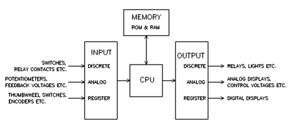
Fig 20 PLC Block Diagram
The main blocks are
i) CPU: It is the centre and most important part of PLC all the processing of input provided is done in this unit. It replaces relays, counters and times. It takes the data input from the various devices connected to it executes the user program from memory and sends the output commands to control devices.
Ii) Programming device: To entre program or code which is in the ladder form we need a keyboard and to read we need a monitor with it.
Iii) Input/Output module: They are used as interface between the input and the microprocessor. The input module transfers the information to the processor and output information from the processor to the load through output module. The input module is shown below.
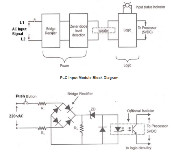
Fig 17 Circuit Diagram for PLC input module
There a power unit and a logical unit as seen above in the input module. A 220V ac is applied to the bridge rectifier when a push button is closed. The dc output is generated through the rectifier and Zener diode provides the low voltage to LED. The phototransistor conducts when the LED light strikes them and provides dc voltage to the processor.
The output module acts as an interface between output load and processor. It also has power and logical unit but works in reverse order to that of input module. The phototransistor will conduct when the light from LED strikes it happens when the processor generates high signal.
Key takeaway
It uses sequence programming which has open and closed contacts connected in parallel or series. They take input in the form of instructions fed through a software. The CPU receives the instructions and decodes them.
There is always a memory map available with the microprocessor-based systems. The Allen-Bradley brand is the most commonly used PLC brand. In this section we will study the I/O addressing for this brand. In Allen Bradley the input and output images are held in data files. The data files have basic information about discrete input/output values, values associated with timers and counters, status information etc.
The memory mapping of I/O is explained by the following example.
For X1:x.0/0
X represents the data file type. This file type can be input (I), output (O), status (S), binary (B), timer (T), counter (C).
1 represents data file number.
: is file separator
x represents slot number.
. is word separator
0(first one after x): represents word number.
0 (last value in the example): represents bit number.
A discrete input file type (I), though, needs to be addressed as individual bits because each separate I/O point refers to a single bit. Thus, I:3/7 would be bit number seven residing in input element three.
The “slash” symbol is necessary when addressing discrete I/O bits because we do not wish to refer to all sixteen bits in a word when we just mean a single input or output point on the PLC.
The timer files are more complex as each timer element consists of two different 16-bit words with three more bits which define the status of the timer. Those three bits are Enabled bit, Timing bit, Done bit.
Basic Instructions Used
- Examine if closed (XIC): This is called as normally open contact. This instruction is used to check if a bit is on. If the bit addressed is on then the instruction is evaluated as true (1) and if 0 then false. The symbol for this instruction is

Fig 18 Instruction symbol
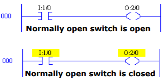
Fig 19 Ladder Logic
- Examine if open (XIO): It is also known as normally closed contact. This instruction is used to check if a bit is off. If the bit addressed is off then the instruction is evaluated as false (1) and if 0 then true. The symbol for this instruction is

Fig 20 Instruction symbol
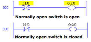
Fig 21 Ladder Logic
- Output energize (OTE): This is used in conjunction with any input instruction. If the logic for this instruction I true (1) the OTE instruction will be energized. The instruction symbol is shown below.

Fig 22 Instruction Symbol
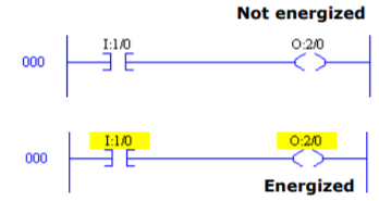
Fig 23 Ladder Logic
- Output Latch (OTP): For turning on any bit and latch it on this instruction is used. The instruction symbol is shown below.

Fig 24 Instruction symbol
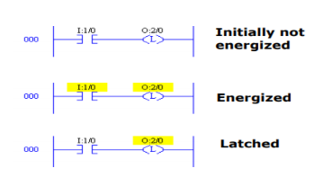
Fig 25 Ladder Logic
- Output Unlatch (OUT): For turning off any bit and latch it off this instruction is used. The OUT and OTL are used in pairs. The instruction symbol is shown below

Fig 26 Instruction symbol

Fig 27 Ladder Logic
- One shot rising (OSR): When the rung conditions preceding the OSR go from false-to true, the OSR instruction goes true also but for only one scan. The address on the OSR instruction is a bit that is used to reflect the state of the input to the OSR.

Fig 28 Instruction Symbol
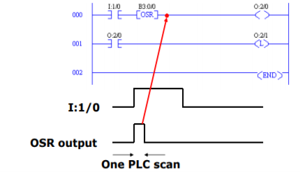
Fig 29 Ladder Logic
- Branches: Branches can be inserted in ladder logic programs to create parallel combinations of various ladder logic elements
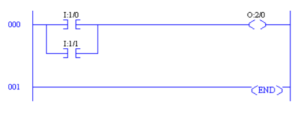
Fig 30 Ladder Logic for parallel combination
Key takeaway
The memory mapping of I/O is explained by the following example.
For X1:x.0/0
The timer files are more complex as each timer element consists of two different 16-bit words with three more bits which define the status of the timer. Those three bits are Enabled bit, Timing bit, Done bit.
- To detect high and low level of liquid in the tank, two level switches are used which gives output in digital terms, that is when corresponding levels are detected, it gives output high otherwise remain low.
- To control level of this system, Single Acting piston valve can be used which has two states, either fully open or fully close.
- Low Level Switch is mounted at the bottom of the tank and Level High switch mounted at the side upper most position.
- When these inputs are detected, output to Control Valve has to be latched in order to continuously fill or empty the system.
- Master start/stop is also provided to shut down or start the entire process.
List of Inputs and Outputs
I:1/0 = Level High Switch (Input)
I:1/1 = Level Low Switch (Input)
O:2/0 = Inlet Valve (Output)
O:2/1 = Outlet Valve (Output)
I:1/14 = Start (Input)
I:1/15 = Stop (Input)
The ladder diagram for the above control process is shown below.
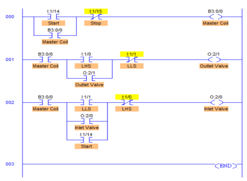
Fig 31 Ladder Diagram for Tank Control
Program Description
- RUNG000 is simply for latching a coil and master start-stop buttons.
- RUNG001 is to control the outlet valve through O:2/1. This is done when Level High is detected.
- Latching of Output O:2/1 is done because when High Level is detected, input to RUNG001 is temporary, like Push Button. So, in order to keep outlet valve open until the Level Low I:1/1 is detected, latching is done. XIO of Level Low Switch is connected in series so that when Level Low is detected, it goes true closing the outlet valve.
- Similarly, in RUNG002, it works exactly same. The only difference in RUNG002 is that extra I:1/14 contact in parallel with LLS.
- Suppose when the system is started and the tank is partially filled, neither LHS nor LLS is detected, in this case, outlet and inlet valves remain closed while inlet valve should open to start filling the tank because it’s partially filled.
- To eliminate this error, I:1/14 (Start) is connected in parallel to LLS I:1/1 contact. This checks if LHS (I:1/0) is detected or not. If LHS is not detected, then it opens the inlet valve until LHS is detected.
Reference:
1 A. Ananadkumar, “Control system Engineering” PHI publication 2nd edition.
2 R. Anandanatarajan, P. Ramesh Babu , “Control Systems Engineering”, Scitech Publications .
3 John R. Hackworth,Fredrick D. Hackworth “ Programmable Logic Controller” Pearson publication.
4 I.J. Nagrath, M.Gopal “Control Systems Engineering”, 5th Edition, New Age International