UNIT- 6
Spread Spectrum Modulation
An RF communications system in which the baseband signal bandwidth is intentionally spread over a larger bandwidth by injecting a higher frequency signal. As a direct consequence, energy used in transmitting the signal is spread over a wider bandwidth, and appears as noise. The ratio (in dB) between the spread baseband and the original signal is called processing gain.
To apply a spread-spectrum technique, simply inject the corresponding spread-spectrum code somewhere in the transmitting chain before the antenna (receiver). (That injection is called the spreading operation.) The effect is to diffuse the information in a larger bandwidth.
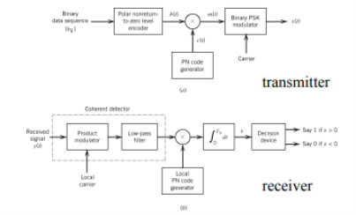
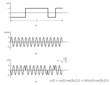
Direct Sequence Spread Spectrum (DSSS) using BPSK modulation, so the first reversing switch introduces 180-degree phase reversals according to a pseudo-random code, while the second introduces the same reversals to reconstitute the original, narrow-band signal. The output is a “recompressed” narrow-band signal.
DSSS is a spread spectrum modulation technique used for digital signal transmission over airwaves. It was originally developed for military use, and employed difficult-to-detect wideband signals to resist jamming attempts.
It is also being developed for commercial purposes in local and wireless networks.
The stream of information in DSSS is divided into small pieces, each associated with a frequency channel across spectrums. Data signals at transmission points are combined with a higher data rate bit sequence, which divides data based on a spreading ratio. The chipping code in a DSSS is a redundant bit pattern associated with each bit transmitted.
This helps to increase the signal's resistance to interference. If any bits are damaged during transmission, the original data can be recovered due to the redundancy of transmission.
The entire process is performed by multiplying a radio frequency carrier and a pseudo-noise (PN) digital signal. The PN code is modulated onto an information signal using several modulation techniques such as quadrature phase-shift keying (QPSK), binary phase-shift keying (BPSK), etc. A doubly-balanced mixer then multiplies the PN modulated information signal and the RF carrier. Thus, the TF signal is replaced with a bandwidth signal that has a spectral equivalent of the noise signal. The demodulation process mixes or multiplies the PN modulated carrier wave with the incoming RF signal. The result produced is a signal with a maximum value when two signals are correlated. Such a signal is then sent to a BPSK demodulator. Although these signals appear to be noisy in the frequency domain, bandwidth provided by the PN code permits the signal power to drop below the noise threshold without any loss of information.
|
Fig.1: DSSS
Key Takeaways:
- Direct Sequence Spread Spectrum (DSSS) using BPSK modulation, so the first reversing switch introduces 180-degree phase reversals according to a pseudo-random code.
- DSSS is a spread spectrum modulation technique used for digital signal transmission over airwaves. It was originally developed for military use, and employed difficult-to-detect wideband signals to resist jamming attempts.
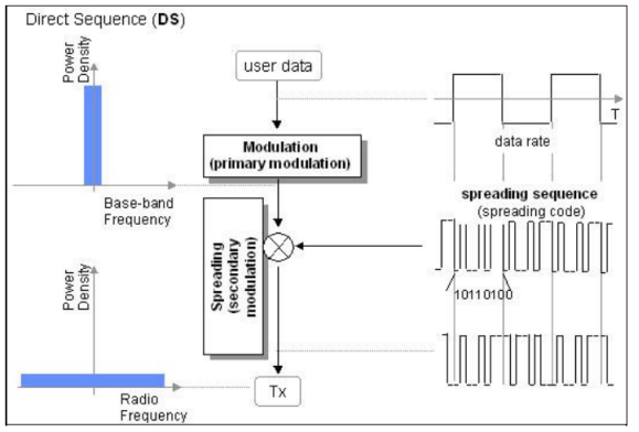
In this method, the direct sequence (input data) which is spread over a limited bandwidth is multiplied with a code or spreading sequence (a pseudorandom sequence also known as PN sequence) which will spread the input data over the entire bandwidth of the communication channel. The power density is also reduced and is spread over the frequency spectrum and hence is known as spread spectrum method. The modulation part of DSSS is as shown below.
|
Fig.2: CDMA Modulation
CDMA Modulation
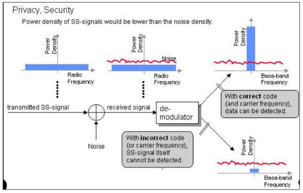
The modulated signal is transmitted over the channel and all users can receive it but only the user which knows the correct code can decode the message. This is depicted in the figure above.
CDMA Demodulation
CDMA's spread spectrum technique overlaps every transmission on the same carrier frequency by assigning a unique code to each conversation.
The signal is spread at two levels first using a Walsh Code and then using a PN Code. The number of bits in either of the two codes is known as the "chip rate," and each bit in the spreading signal is called a "chip". One bit from each conversation (baseband signal) is multiplied with the walsh code and then the PN code by the spreading techniques, giving the receiving side an enormous amount of data, it can average just to determine the value of one bit.
Base station is the one that assigns spreading code to each call when a mobile request for a call (unique Walsh code for each conversation and a same PN code for each call in a cell sector). In the analysis henceforth we discuss the dynamic allocation of these spread codes in accordance with the required QoS.
|
Fig.3: CDMA demodulation
Key Takeaways:
- The modulated signal is transmitted over the channel and all users can receive it but only the user which knows the correct code can decode the message.
- Base station is the one that assigns spreading code to each call when a mobile request for a call (unique Walsh code for each conversation and a same PN code for each call in a cell sector).
Assume coherent detection SNR before spreading
SNR after spreading
Orthonormal basis vused at the receiver end
SNR before spreading (SNR)
SNR afterv spreading
|
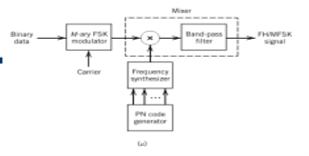
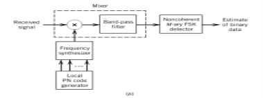
This is frequency hopping technique, where the users are made to change the frequencies of usage, from one to another in a specified time interval, hence called as frequency hopping. For example, a frequency was allotted to sender 1 for a particular period of time. Now, after a while, sender 1 hops to the other frequency and sender 2 uses the first frequency, which was previously used by sender 1. This is called as frequency reuse.
The frequencies of the data are hopped from one to another in order to provide a secure transmission. The amount of time spent on each frequency hop is called as Dwell time.
|
Fig.4: FHSS
Comparison between FHSS and DSSS
.
FHSS | DSSS |
Multiple frequencies are used | Single frequency is used |
Hard to find the user’s frequency at any instant of time | User frequency, once allotted is always the same |
Frequency reuse is allowed | Frequency reuse is not allowed |
Sender need not wait | Sender has to wait if the spectrum is busy |
Power strength of the signal is high | Power strength of the signal is low |
Stronger and penetrates through the obstacles | It is weaker compared to FHSS |
It is never affected by interference | It can be affected by interference |
It is cheaper | It is expensive |
This is the commonly used technique | This technique is not frequently used |
A pseudo-noise code (PN code) or pseudo-random-noise code (PRN code) is one that has a spectrum similar to a random sequence of bits but is deterministically generated. The most commonly used sequences in direct-sequence spread spectrum systems are maximal length sequences, Gold codes, Kasami codes, and Barker codes.
A pseudorandom binary sequence (PRBS) is a binary sequence that, while generated with a deterministic algorithm, is difficult to predict and exhibits statistical behavior similar to a truly random sequence. PRBS generators are used in telecommunication, such as in analog-to-information conversion, but also in encryption, simulation, correlation technique.
A binary sequence (BS) is a sequence
ABS consist of ABS is a pseudorandom binary sequence (PRBS) if its autocorrelation given by
Has only two values
is called the duty cycle of the PRBS, similar to the duty cycle of a continuous time signal. For a maximum length sequence, where
|
A PN data sequence is an M-sequence that is generated using a linear feedback shift-register circuit, as illustrated below. M is the number of shift registers. D(M) is the mth shift register, and {c1,c2,…,cM} are the coefficients of them. At each clock pulse, the data in the registers will right shift once and one PN datum is output from register D(M).
|
Mathematically, the procedure can be defined by a generator polynomial. {c1,c2,…,cM} becomes the coefficients of the generator polynomial. For instance, the polynomial for PN9 is x9+x5+1, therefore, M=9 and c9=1, c5=1, ci∈{1~9},and i≠9,i≠5=0
The PN sequence, {an}, 0 ≤ n < 2M, is generated by the equation below.
|
where, the initial state of registers {D1,D2…DM} is the seed. D(M) stores the LSB of the seed, and D1 stores the MSB of the seed. For example, if the seed is 10 (binary form 1010), the initial state in register {D1,D2…DM} is {0 0 0 0 0 1 0 1 0}. The figure below shows the initial state of each register for PN9. It’s obvious that LSB of the seed comes out first.
Afterwards, the registers store previously generated data, Dm=an-m,m∈(1,M).
The generator polynomial for PN15 is x15+x14+1, therefore M=15 and c15=1, c14=1, ci∈{1~15},and i≠15,i≠14=0.
|
Reference:
1. P RamkrishnaRao, Digital Communication, McGrawHill Publication
2. Ha Nguyen, Ed Shwedyk, ―A First Course in Digital Communication‖, Cambridge
University Press.
3. B P Lathi, Zhi Ding ―Modern Analog and Digital Communication System‖, Oxford
University Press, Fourth Edition.
4. Bernard Sklar, Prabitra Kumar Ray, ―Digital Communications Fundamentals and
Applications‖ Second Edition,Pearson Education
5. Taub, Schilling, ―Principles of Communication System‖, Fourth Edition, McGraw Hill.
