● A dipole whose length is far less than wavelength is infinitesimal dipole. This antenna is actually impractical. Here, the length of the dipole is less than even fiftieth part of the wavelength.
● The length of the dipole, Δl <<λ. Where, λ is the wavelength.
Δl=λ/50
Hence, this is the infinitely small dipole, as the name implies.
● As the length of these dipoles is very small, the current flow in the wire will be dI. These wires are generally used with capacitor plates on both sides, where low mutual coupling is needed. Because of the capacitor plates, we can say that uniform distribution of current is present. Hence the current is not zero here.
● The capacitor plates can be simply conductors or the wire equivalents. The fields radiated by the radial currents tend to cancel each other in the far field so that the far fields of the capacitor plate antenna can be approximated by the infinitesimal dipole.
● The radiation pattern of infinitesimal dipole is similar to a half wave dipole. If the dipole is vertical, the pattern will be circular. The radiation pattern is in the shape of “figure of eight” pattern, when viewed in two-dimensional pattern.
● The following figure shows the radiation pattern of infinitesimal antenna, which is in omni-directional pattern.
|
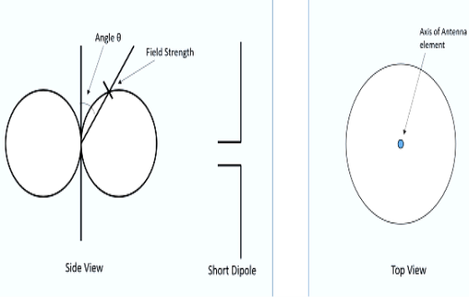
Figure 3.1.1Radiation pattern of Infinitesimal Dipole
3.1.2. Advantages
The following are the advantages of short dipole antenna −
● Ease of construction, due to small size
3.1.3. Disadvantages
The following are the disadvantages of infinitesimal dipole antenna −
● High resistive losses
● High power dissipation
● Low Signal-to-noise ratio
● Radiation is low
● Not so efficient
3.1.4. Applications
The following are the applications of infinitesimal dipole antenna −
● Used in narrow band applications.
● Used as an antenna for tuner circuits.
Key takeaways:
● A dipole whose length is far less than wavelength is infitesimal dipole. This antenna is actually impractical. Here, the length of the dipole is less than even fiftieth part of the wavelength.
● The radiation pattern is in the shape of “figure of eight” pattern, when viewed in two-dimensional pattern.)
● The dipole antenna is cut and bent for effective radiation. The length of the total wire, which is being used as a dipole, equals half of the wavelength (i.e., l = λ/2). Such an antenna is called as half-wave dipole antenna.
● This is the most widely used antenna because of its advantages. It is also known as Hertz antenna.
3.2.1. Frequency range
● The range of frequency in which half-wave dipole operates is around 3 KHz to 300GHz. This is mostly used in radio receivers.
3.2.2. Construction & Working of Half-wave Dipole
● It is a normal dipole antenna, where the frequency of its operation is half of its wavelength. Hence, it is called as half-wave dipole antenna.
● The edge of the dipole has maximum voltage. This voltage is alternating (AC) in nature.
● At the positive peak of the voltage, the electrons tend to move in one direction and at the negative peak, the electrons move in the other direction. This can be explained by the figures given below.
|
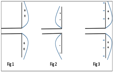
Figure 3.2 Working of a half-wave dipole.
● Fig 1 shows the dipole when the charges induced are in positive half cycle. Now the electrons tend to move towards the charge.
● Fig 2 shows the dipole with negative charges induced. The electrons here tend to move away from the dipole.
● Fig 3 shows the dipole with next positive half cycle. Hence, the electrons again move towards the charge.
● The cumulative effect of this produces a varying field effect which gets radiated in the same pattern produced on it.
● Hence, the output would be an effective radiation following the cycles of the output voltage pattern. Thus, a half-wave dipole radiates effectively.
Key takeaways:
● The dipole antenna is cut and bent for effective radiation.
● The length of the total wire, which is being used as a dipole, equals half of the wavelength (i.e., l = λ/2). Such an antenna is called as half-wave dipole antenna. (It is also known as Hertz antenna.)
● Waves radiated from the antenna directly downward reflect vertically from the ground and, in passing the antenna on their upward journey, induce a voltage in it. The magnitude and phase of the current resulting from this induced voltage depends on the height of the antenna above the reflecting surface.
● The total current in the antenna consists of two components. The amplitude of the first is determined by the power supplied by the transmitter and the free-space feed-point resistance of the antenna.
● The second component is induced in the antenna by the wave reflected from the ground. This second component of current, while considerably smaller than the first at most useful antenna heights.
● At some heights, the two components will be in phase, so the total current is larger than is indicated by the free-space feed-point resistance. At other heights, the two components are out of phase, and the total current is the difference between the two components.
● Changing the height of the antenna above ground will change the amount of current flow, assuming that the power input to the antenna is constant. A higher current at the same power input means that the effective resistance of the antenna is lower, and vice versa.
● In other words, the feed-point resistance of the antenna is affected by the height of the antenna above ground because of mutual coupling between the antenna and the ground beneath it.
● Different impedance values may be encountered when an antenna is erected at identical heights but over different types of earth.
|
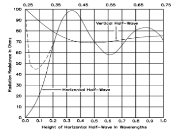
Figure 3.3. Effect of ground in Reactive near field
● Above Fig shows the way in which the radiation resistance of horizontal and vertical half-wave antennas vary with height above ground (in λ, wavelengths). For horizontally polarized half-wave antennas, the differences between the effects of perfect ground and real earth are negligible.
● If the antenna height is greater than 0.2 λ. At lower heights, the feed-point resistance over perfect ground decreases rapidly as the antenna is brought closer to a theoretically perfect ground, but this does not occur so rapidly for actual ground.
● Over real earth, the resistance begins increasing at heights below about 0.08 λ. The reason for the increasing resistance at very low heights is that more and more of the reactive (induction) field of the antenna is absorbed by the lossy ground in close proximity.
Key takeaways:
● Changing the height of the antenna above ground will change the amount of current flow, assuming that the power input to the antenna is constant.)
● A monopole antenna is one half of a dipole antenna, almost always mounted above some sort of ground plane.
● The case of a monopole antenna of length L mounted above an infinite ground plane is shown in Figure below (a).
|
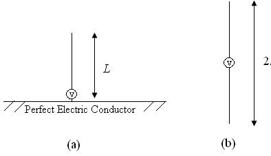
Figure 3.4. Monopole above a PEC (a), and the equivalent source in free space (b).
● Using image theory, the fields above the ground plane can be found by using the equivalent source (antenna) in free space as shown in Figure 1(b).
● This is simply a dipole antenna of twice the length. The fields above the ground plane in Figure 1(a) are identical to the fields in Figure 1(b), which are known and presented in the dipole antenna section.
● The monopole antenna fields below the ground plane in Figure 1(a) are zero.
3.4.1. Radiation Pattern
● The radiation pattern of monopole antennas above a ground plane are also known from the dipole result. The only change that needs to be noted is that the impedance of a monopole antenna is one half of that of a full dipole antenna.
● For a quarter-wave monopole (L=0.25* ), the impedance is half of that of a half-wave dipole, so
Zin = 36.5 + j21.25 Ohms.
● This can be understood since only half the voltage is required to drive a monopole antenna to the same current as a dipole. Since Zin = V/I, the impedance of the monopole antenna is halved.
Key takeaways:
● A monopole antenna is one half of a dipole antenna, almost always mounted above some sort of ground plane.
● The impedance of a monopole antenna is one half of that of a full dipole antenna.
● The folded dipole antenna consists of a basic dipole, but with an added conductor connecting the two ends together. This makes a ‘loop’ of wire that is a short circuit to DC. As the ends appear to be folded back, the antenna is called a folded dipole antenna.
● The basic format for the folded dipole aerial is shown below. Like the basic dipole, the folded dipole antenna is a balanced antenna, and needs to be fed with a balanced feeder.
● Unbalanced feeders can be used provided that a balun (unbalanced to balanced transformer) is used.
|
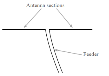
Figure 3.5. Basic dipole antenna
● One of the main reasons for using a folded dipole antenna is the increase in feed impedance that it provides. If the conductors in the main dipole and the second or "fold" conductor are the same diameter, then it is found that there is a fourfold increase (i.e. two squared) in the feed impedance.
● In free space, this gives an increase in feed impedance from 73Ω to around 300Ω ohms. Additionally the RF antenna has a wider bandwidth.
3.5.1. Folded dipole advantages
There are two main advantages for using a folded dipole antenna over a standard dipole:
● Increase in impedance
When higher impedance feeders need to be used, or when the impedance of the dipole is reduced by factors such as parasitic elements, a folded dipole provides a significant increase in impedance level that enables the antenna to be matched more easily to the feeder available.
● Wide bandwidth
The folded dipole antenna has a flatter frequency response - this enables it to be used over a wider bandwidth with many transmissions utilising a variety of different selectable channels, e.g. television and broadcast radio, a wide bandwidth antenna is needed. The standard dipole antenna does not always provide the required bandwidth and the additional bandwidth of the folded dipole meets the requirements.
3.5.2. Folded dipole applications
There are many ways in which folded dipoles can be used. They find uses in many applications:
● On their own
Folded dipole antennas are sometimes used on their own, but they must be fed with a high impedance feeder, typically 300 ohms. This on its own can be very useful in certain applications where balanced feeders may be used.
● As part of another antenna
However folded dipoles find more uses when a dipole is incorporated in another RF antenna design with other elements nearby. The issue is that incorporating a dipole into an antenna such as a Yagi where elements are closely coupled reduces the feed impedance. If a simple dipole was used, then the feed impedance levels of less than 20 Ω or less can easily be experienced.
● Using a folded dipole enables the impedance to be increased by a factor of four or whatever is required by having multiple wires in the folded dipole.
● Increased bandwidth
Sometimes folded dipoles may be employed purely to give a greater bandwidth. When used to increase bandwidth, folded dipoles may be used on their own or within another antenna system.
Key takeaways:
● The folded dipole antenna consists of a basic dipole, but with an added conductor connecting the two ends together.
● This makes a ‘loop’ of wire that is a short circuit to DC. As the ends appear to be folded back, the antenna is called a folded dipole antenna.)
● An RF current carrying coil is given a single turn into a loop, can be used as an antenna called as loop antenna.
● The currents through this loop antenna will be in phase. The magnetic field will be perpendicular to the whole loop carrying the current.
3.6.1. Frequency Range
The frequency range of operation of loop antenna is around 300MHz to 3GHz. This antenna works in UHF range.
3.6.2. Construction & Working of Loop Antennas
A loop antenna is a coil carrying radio frequency current. It may be in any shape such as circular, rectangular, triangular, square or hexagonal according to the designer’s convenience.
Loop antennas are of two types.
● Large loop antennas
● Small loop antennas
3.6.3. Large loop antennas
● Large loop antennas are also called as resonant antennas. They have high radiation efficiency. These antennas have length nearly equal to the intended wavelength.
L=λ
Where,
● L is the length of the antenna
● λ is the wavelength
● The main parameter of this antenna is its perimeter length, which is about a wavelength and should be an enclosed loop Small loop antenna
3.6.4. Small loop antennas
● Small loop antennas are also called as magnetic loop antennas. These are less resonant. These are mostly used as receivers.
● These antennas are of the size of one-tenth of the wavelength.
L=λ/10
Where,
● L is the length of the antenna
● λ is the wavelength
3.6.4.1. The features of small loop antenna
● A small loop antenna has low radiation resistance. If multi-turn ferrite core constructions are used, then high radiation resistance can be achieved.
● It has low radiation efficiency due to high losses.
● Its construction is simple with small size and weight.
Due to its high reactance, its impedance is difficult to match with the transmitter. If loop antenna have to act as transmitting antenna, then this impedance mis-match would definitely be a problem. Hence, these loop antennas are better operated as receiver antennas.
● The radiation pattern of these antennas will be same as that of short horizontal dipole antenna.
|
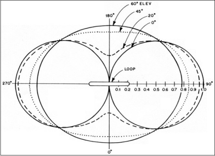
● The radiation pattern for small, high-efficiency loop antennas is shown in the figure given above. The radiation patterns for different angles of looping are also illustrated clearly in the figure.
● The tangent line at 0° indicates vertical polarization, whereas the line with 90° indicates horizontal polarization.
3.6.6. Advantages
The following are the advantages of Loop antenna −
● Compact in size
● High directivity
3.6.7. Disadvantages
The following are the disadvantages of Loop antenna −
● Impedance matching may not be always good
● Has very high resonance quality factor
3.6.8. Applications
The following are the applications of Loop antenna −
● Used in RFID devices
● Used in MF, HF and Short wave receivers
● Used in Aircraft receivers for direction finding
● Used in UHF transmitters
Key takeaways:
● An RF current carrying coil is given a single turn into a loop, can be used as an antenna called as loop antenna.
● The frequency range of operation of loop antenna is around 300MHz to 3GHz. This antenna works in UHF range.)
3.6.7. Helical Antenna
Helical antenna is an example of wire antenna and itself forms the shape of a helix. This is a broadband VHF and UHF antenna.
3.6.7.1. Frequency Range
The frequency range of operation of helical antenna is around 30MHz to 3GHz. This antenna works in VHF and UHF ranges.
3.6.7.2. Construction & Working of Helical Antenna
● Helical antenna or helix antenna is the antenna in which the conducting wire is wound in helical shape and connected to the ground plate with a feeder line.
● It is the simplest antenna, which provides circularly polarized waves. It is used in extra-terrestrial communications in which satellite relays etc., are involved.
|
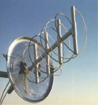
Figure 3.6.7.2. Helical Antenna
● The above image shows a helical antenna system, which is used for satellite communications. These antennas require wider outdoor space.
● It consists of a helix of thick copper wire or tubing wound in the shape of a screw thread used as an antenna in conjunction with a flat metal plate called a ground plate.
● One end of the helix is connected to the center conductor of the cable and the outer conductor is connected to the ground plate.
● The image of a helix antenna detailing the antenna parts is shown above.
The radiation of helical antenna depends on the diameter of helix, the turn the pitch angle.
● Pitch angle is the angle between a line tangent to the helix wire and plane normal to the helix axis.
α=tan−1(S/πD)
where ,
● D is the diameter of helix.
● S is the turn spacing (centre to centre).
3.6.8. Modes of Operation
The predominant modes of operation of a helical antenna are −
● Normal or perpendicular mode of radiation.
● Axial or end-fire or beam mode of radiation.
3.6.8.1. Normal Mode
● In normal mode of radiation, the radiation field is normal to the helix axis. The radiated waves are circularly polarized.
● This mode of radiation is obtained if the dimensions of helix are small compared to the wavelength.
● The radiation pattern of this helical antenna is a combination of short dipole and loop antenna.
|
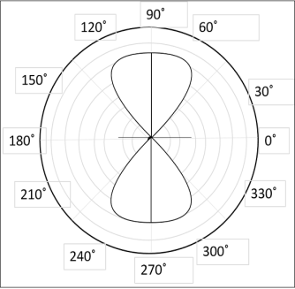
Figure 3.6.8.1.Radiation pattern for normal mode of radiation in helical antenna
● It depends upon the values of diameter of helix, D and its turn spacing, S. Drawbacks of this mode of operation are low radiation efficiency and narrow bandwidth. Hence, it is hardly used.
3.6.8.2. Axial Mode
● In axial mode of radiation, the radiation is in the end-fire direction along the helical axis and the waves are circularly or nearly circularly polarized.
● This mode of operation is obtained by raising the circumference to the order of one wavelength (λ) and spacing of approximately λ/4.
● The radiation pattern is broad and directional along the axial beam producing minor lobes at oblique angles.
|
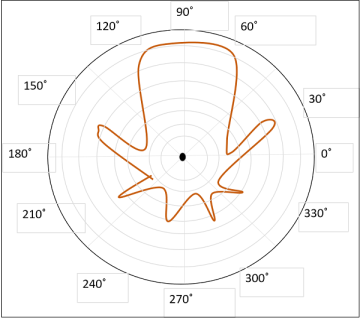
Figure 3.6.8.2. Radiation pattern for axial mode of radiation in helical antenna
● If this antenna is designed for right-handed circularly polarized waves, then it will not receive left-handed circularly polarized waves and vice versa.
● This mode of operation is generated with great ease and is more practically used.
3.6.9. Advantages
The following are the advantages of Helical antenna −
● Simple design
● Highest directivity
● Wider bandwidth
● Can achieve circular polarization
● Can be used at HF & VHF bands also
3.6.10. Disadvantages
The following are the disadvantages of Helical antenna −
● Antenna is larger and requires more space
● Efficiency decreases with number of turns
3.6.11. Applications
The following are the applications of Helical antenna −
● A single helical antenna or its array is used to transmit and receive VHF signals.
● Frequently used for satellite and space probe communications.
● Used for telemetry links with ballastic missiles and satellites at Earth stations.
● Used to establish communications between the moon and the Earth.
● Applications in radio astronomy.
Key takeaways:
● Helical antenna is an example of wire antenna and itself forms the shape of a helix. This is a broadband VHF and UHF antenna.
● In normal mode of radiation, the radiation field is normal to the helix axis. The radiated waves are circularly polarized.
● In axial mode of radiation, the radiation is in the end-fire direction along the helical axis and the waves are circularly or nearly circularly polarized.)
The variation in the number of helix turns improves the antenna gain and bandwidth by changing the plasma frequency. An improvement in antenna gain and radiation efficiency is achieved by loading the antenna with shaped dielectric lenses with a different cross section.
● V antenna is a type of long wire antenna whose structure is designed in the form of a V. This is the reason it is given the name V antenna.
● It operates in the high-frequency range between 3 to 30 MHz.
● Basically, it is said to be an enhanced version of a long wire antenna that provides higher gain and directivity than long wire antenna.
● It is generally a resonant antenna that provides bidirectional radiation. However, proper impedance matching leads to provide a non-resonant antenna also that produces unidirectional radiation.
● A V antenna is a combination of two long wire antennas that are joined in the form of a horizontal V structure. The excitation to this antenna is provided at the apex using feed lines. And the two wires of the V antennas are referred as legs.
● The figure below shows the structure of V antenna:
|
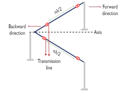
Figure 3.8.1.1. Structure of V antenna
● The arrangement shown above is resonant type V antenna as the two ends of the antennas are non-terminated.
● As we can see here that the feed line to the antenna is provided at the joining angle of the two legs. This angle is known as apex. It is denoted
By α.
|
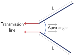
. Figure 3.8.1.2. Construction of V antenna
● In comparison to a single long wire antenna, the gain offered by it is 2 times more.
● In case of these antennas, if the length of each leg is 8λ, then it can provide a gain of about 12 dB. It is to be noted that the apex angle shows dependency on the length of the leg.
3.8.2. Radiation Pattern of V Antenna
● The figure given below is representing the radiation pattern for the resonant type of V antenna:
|
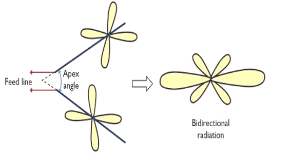
Figure 3.8.2.1. Radiation pattern of resonant v antenna
● Now, have a look at the radiation pattern of the non-resonant type of antenna, showing unidirectional radiation pattern:
|
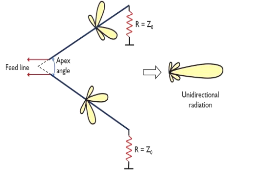
Figure 3.8.2.2. Radiation pattern of non-resonant v antenna
● In the case of a vertical arrangement, the two or more antennas can be stacked one above the other. While in a horizontal manner these can be arranged in broadside.
● Here is no reflector is used in case of the array with elements as V antenna.
- The low cost of the V antenna is one of its greatest advantages.
- It offers high bandwidth.
- It is quite easy to construct.
- The offered directive gain is high.
- A resonant as well as non-resonant both provides side lobes of great strength.
- The non-terminated ends of the antenna give rise to standing waves.
- It needs quite a large space for installation.
3.8.5. Applications of V Antenna
These antennas have their maximum applications in radio communication for commercial purpose. Also, their high gain and directivity support long-distance communication at a fixed frequency.
Key takeaways:
● V antenna is a type of long wire antenna whose structure is designed in the form of a V. This is the reason it is given the name V antenna.
● It operates in the high-frequency range between 3 to 30 MHz . Basically, it is said to be an enhanced version of a long wire antenna that provides higher gain and directivity than long wire antenna.)
● The Yagi antenna or Yagi-Uda antenna or aerial is a particularly popular form of antenna where directivity and gain are required.
● Although the Yagi has become particularly popular for television reception, it is also used in many other applications, both domestic and commercial or professional.
● The gain and directivity of the Yagi antenna enable improved reception by enabling better levels of signal to noise ratio to be achieved, and by reducing interference levels by only picking up signals from a given direction.
● For transmitting much better use of the available power is made because it is possible to focus the transmitted power on areas where it is needed.
● Similarly levels of general interference can be reduced to other users because the signal is not transmitted to areas where it is not needed.
3.9.1 Construction
|
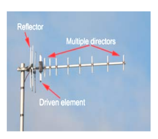
Figure 3.9.1. Yagi antenna components
There are three types of element within a Yagi antenna:
● Driven element: The driven element is the Yagi antenna element to which power is applied. It is normally a half wave dipole or often a folded dipole.
● Reflector: The reflector element is made to be about 5% longer than the driven element. The Yagi antenna will generally only have one reflector. This is behind the main driven element, i.e. the side away from the direction of maximum sensitivity.
● Further reflectors behind the first one make no noticeable different to the antenna performance. However many designs use reflectors consisting of a reflecting plate, or a series of parallel rods simulating a reflecting plate. This gives a slight improvement in performance, reducing the level of radiation or pick-up from behind the antenna, i.e. in the backwards direction. Tis can help
in reducing the levels of interference received.
Typically a reflector will add around 4 or 5 dB of gain in the forward direction.
● Director: The director or directors are made to be shorter than the driven element. There may be none, one of more reflectors in the Yagi antenna. The director or directors are placed in front of the driven element, i.e. in the direction of maximum sensitivity. Typically each director will add around 1 dB of gain in the forward direction, although this level reduces as the number of directors increases.
3.9.2. Radiation Pattern.
|
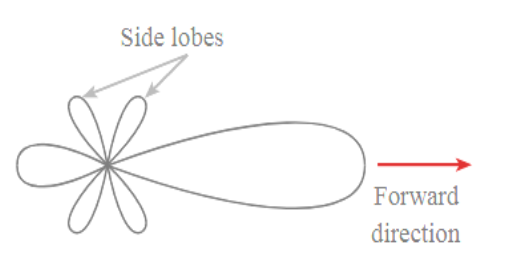
Figure 3.9.2. Radiation Pattern of Yagi- Uda Antenna
● The antenna can be optimised to either reduce radiation in the reverse direction by altering the length and spacing of the reflector or it can be optimised to produce the maximum level of forward gain.
● Unfortunately, the two conditions do not coincide exactly and a compromise on the performance has to be made depending upon the application. It is necessary to choose either maximum front to back ratio or maximum forward gain.
3.9.3. Advantages
● Directivity
The Yagi antenna is directional enabling interference levels to be minimised for receiving and transmitting.
● Gain
The Yagi antenna has gain allowing lower strength signals to be received.
● Straightforward construction
The Yagi antenna is mechanically relatively straightforward when compared to other designs. It can be constructed using straight rods which are simple to use and robust for most instances.
● Polarisation
The construction enables the antenna to be mounted easily on vertical and other poles with standard mechanical fixings
3.9.4. Disadvantages
● Max gain ~20dB Gain is limited to around 20dB or so for a single antenna otherwise it becomes too large and beamwidth narrows. For low frequency antennas the physical size means that the maximum number of elements and hence the gain is much lower than 20dB.
● Long for high gain: For high gain levels the antenna becomes very long.
Key takeaways:
● The Yagi antenna or Yagi-Uda antenna or aerial is a particularly popular form of antenna where directivity and gain are required.
● The gain and directivity of the Yagi antenna enable improved reception by enabling better levels of signal to noise ratio to be achieved, and by reducing interference levels by only picking up signals from a given direction.)
References
● “Antenna Theory: Analysis and Design” by Constantine A Balanis.
● G. S. N. Raju, “Antennas and Wave Propagation”, Pearson Education.
● 2. K. D. Prasad, “Antenna and Wave Propagation”, Satya Prakashan.


