Unit-4
Antennas for Different Applications
● A horn antenna is used to transmit radio waves from a waveguide (a metal pipe used to carry radio waves) out into space, or collect radio waves into a waveguide for reception.
● It typically consists of a short length of rectangular or cylindrical metal tube (the waveguide), closed at one end, flaring into an open-ended conical or pyramidal shaped horn on the other end.
● The radio waves are usually introduced into the waveguide by a coaxial cable attached to the side, with the central conductor projecting into the waveguide to form a quarter-wave monopole antenna.
● The waves then radiate out the horn end in a narrow beam. In some equipment the radio waves are conducted between the transmitter or receiver and the antenna by a waveguide; in this case the horn is attached to the end of the waveguide.
● In outdoor horns, such as the feed horns of satellite dishes, the open mouth of the horn is often covered by a plastic sheet transparent to radio waves, to exclude moisture.
A pyramidal horn with only one pair of sides flared and the other pair parallel. It produces a fan-shaped beam, which is narrow in the plane of the flared sides, but wide in the plane of the narrow sides. These types are often used as feed horns for wide search radar antennas.
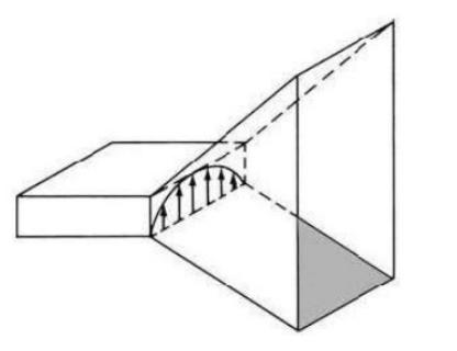
● .E-plane horn – A sectoral horn flared in the direction of the electric or E-field in the waveguide.
● H-plane horn – A sectoral horn flared in the direction of the magnetic or H-field in the waveguide.
Key takeaways :
● A pyramidal horn with only one pair of sides flared and the other pair parallel. It produces a fan-shaped beam, which is narrow in the plane of the flared sides.)
|
Figure 4.3. E-Plane horn
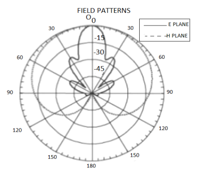
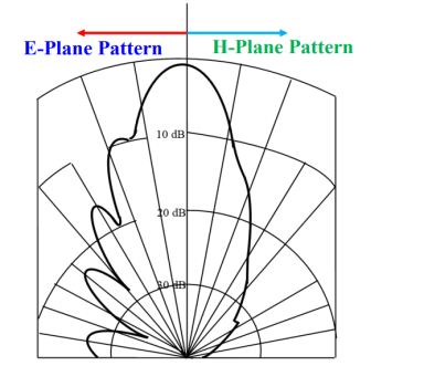
4.3.1. Radiation pattern of E-Plane horn
The E pattern is much narrower than H plane because of the flaring and larger dimensions of the horn in the directions.
|
Figure 4.3.1. Radiation pattern of E-Plane horn
● It is assumed that, there exist a line source radiating cylindrical waves at the imaginary apex of the horn. As waves travel in the outward radial direction, the constant phase fronts are cylindrical which do not coincide with aperture plane.
● At any point y’ at the aperture of the horn, the phase of the field will not be the same as that at the origin.
● The phase difference because the wave travelled different distances from the apex to the aperture.
● The difference in path of travel, designated as δ(y’),can be obtained as follows
4.3.2. Aperture phase distribution

 =
= 
 =
=  ………. Exact spherical
 =
=  =
= 
 …….. Quadratic distance variation
4.3.3. Aperture Fields
● When δ(y’) is multiplied by the phase constant k, the result is a quadratic phase variation between the constant phase surface and the aperture plane.
● So the aperture fields becomes…..
 (
( ) =
) = 

 Amplitude distribution
 = Phase distribution
 (
( ) =
) = 
4.3.4. Directivity
The directivity of the E-plane sectoral horn is found in a manner analogous to the H-plane sectoral horn:
 =
=  =
= 
Where,
 =
=  ,
,  =
=  , q =
, q =
|
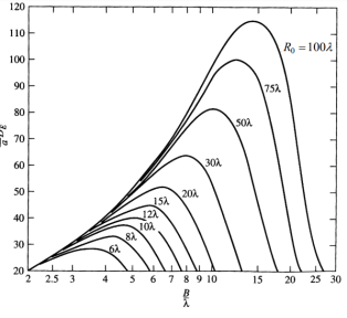
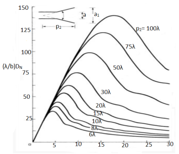
Figure 4.3.4. Directivity of E plane
Maximum Directivity occurs when

Key takeaways:
● The E pattern is much narrower than H plane because of the flaring and larger dimensions of the horn in the directions.
● The directivity of the E-plane sectoral horn is found in a manner analogous to the H-plane sectoral horn:
 =
=  =
= 
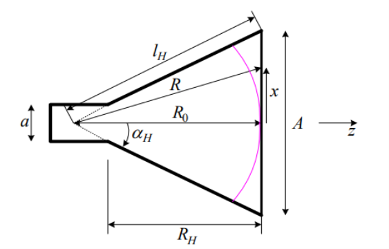
The geometry and the respective parameters shown in the figure below are used in the subsequent analysis. The two required dimensions for the construction of the horn are A and  .
.
 = -
= -
|
Figure 4.4. H-plane sectoral horn
4.4.1. Directivity
The directivity of the H-plane sectoral horn is maximum when,

|
Figure 4.4.1. Directivity of H sectoral horn
Maximum Phase error occurs when x’ = a1
Δmax = 2πt, where, t=
Whichgives ‘t’ approximately equal to:
 =
=  at
at  =
= 
Key takeaways:
● H sectoral horn is less narrow than E sectoral horn.
● The directivity of the H-plane sectoral horn is maximum when, )
)
● The pyramidal horn is probably the most popular antenna in the microwave frequency ranges (from ≈1 GHz up to ≈18 GHz). The feeding waveguide is flared in both directions, the E-plane and the H-plane.
● The field distribution at the aperture is approximated as

● The E-plane principal pattern of the pyramidal horn is the same as the E-plane principal pattern of the E-plane sectoral horn. The same holds for the H-plane patterns of the pyramidal horn and the H-plane sectoral horn.
● The directivity of the pyramidal horn can be found by introducing the phase efficiency factors of both planes and the taper efficiency factor of the H-plane:
●  =
=  (AB)
(AB)
Where, ,
,  =
=  ,
,
q = ,
,  =
=  ;
;
 =2
=2 [1 +
[1 + ],
],
 =2
=2 [1 +
[1 + ]
]
t =
● The gain of a horn is usually very close to its directivity because the radiation efficiency is very good (low losses). The above expression is a physical optics approximation, and it does not take into account only multiple diffractions, and the diffraction at the edges of the horn arising from reflections from the horn interior.
● These phenomena, which are unaccounted for, lead to only very minor fluctuations of the measured result. That is why horns are often used as gain standards in antenna measurements.
● The optimal directivity of an E-plane horn is achieved at q =1 , =0.8 The optimal directivity of an H-plane horn is achieved at t = 3 / 8)],
 =0.79 .
Thus, the optimal horn has a phase aperture efficiency of
 =0.632
The total aperture efficiency includes the taper factor, too:
 =0.81 *0.632 =0.51
● Therefore, the best achievable directivity for a rectangular waveguide horn is about half that of a uniform rectangular aperture.
4.5.1. Radiation pattern of Pyramidal horn
|
Figure 4.5.1. Radiation pattern of Pyramidal horn
The radiation pattern of pyramidal horn is the combination of E plane and H plane horn.
Key takeaways:
● The pyramidal horn is probably the most popular antenna in the microwave frequency ranges (from ≈1 GHz up to ≈18 GHz).
● The feeding waveguide is flared in both directions, the E-plane and the H-plane.)
● A horn in the shape of a cone, with a circular cross section. They are used with cylindrical waveguides.
● Conical horn is a truncated section of a right circular conical waveguide, and it is usually connected to a circular waveguide or a rectangular waveguide which is gradually transitioned into the circular waveguide.
● It is a basic and popular microwave antenna for many practical applications. Also, it is widely utilized as a gain standard for calibration and gain measurements.
4.6.1. Characteristics
● The gain of antenna ranges to 25 dBi, with 10 to 20 dBi being typical.
● The usable BW of antenna is in the order of 10:1 and can be upto 20:1 that is upto 1GHz to 20 GHz.
● Horns of widely used as antennas
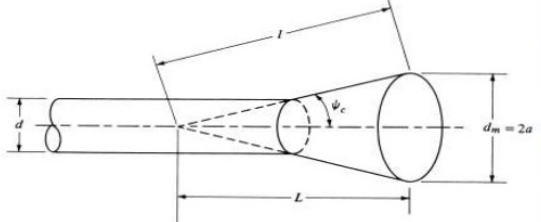
4.6.2. Geometry of conical horn at UHF and microwave frequencies above 300 MHz.
|
Figure 4.6.2. Geometry of conical horn
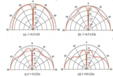
4.6.3. Radiation Pattern
|
Figure 4.6.3. Radiation Pattern
Key takeaways:
● A horn in the shape of a cone, with a circular cross section. They are used with cylindrical waveguides.
● Conical horn is a truncated section of a right circular conical waveguide, and it is usually connected to a circular waveguide or a rectangular waveguide which is gradually transitioned into the circular waveguide.)
● The corrugated horn antenna has parallel slots or grooves along the inside surface of the horn, transverse to the axis. These corrugations are small when compared to the wavelength.
● Corrugated horns have several advantages including a wider bandwidth, and smaller side-lobes that other types. The corrugated horn provides a pattern that is nearly symmetrical, with the E and H plane beam-widths being nearly the same.
● As a result corrugated horn antennas are widely used as feed horns for satellite dishes and radio telescopes.
● These are popularly used as feed horns for dish reflector antennas due to their low side lobe and cross-polarization level. The excited TE mode from a circular waveguide passes along the corrugated inner surface of a circular horn antenna, where a TM mode is also generated.
● When combined, these two modes give lower cross polarization at the antenna aperture. By using this application, the antenna radiation characteristics and aperture cross-polarization ratio can be improved by modifying the geometry of the antenna.
Key takeaways:
● The corrugated horn antenna has parallel slots or grooves along the inside surface of the horn, transverse to the axis.
● These corrugations are small when compared to the wavelength.)
● Designing reflectors are used in radio astronomy, microwave communication, and satellite tracking resulted in spectacular progress in the development of sophisticated analytical and experimental techniques in shaping the reflector surfaces and optimizing illumination over their apertures so as to maximize the gain.
● Although reflector antennas take many geometrical configurations, some of the most popular shapes are the plane, corner, and curved reflectors (especially the paraboloid) .
4.8.1. Types of reflectors antenna
● Plane Reflector
● Corner Reflector
● Parabolic Reflector
● Spherical Reflector
Key takeaways:
● Designing reflectors are used in radio astronomy, microwave communication, and satellite tracking resulted in spectacular progress in the development of sophisticated analytical and experimental techniques in shaping the reflector surfaces and optimizing illumination over their apertures so as to maximize the gain
|
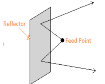
Figure 4.9. Plane Reflector
● The simplest type of reflector is a plane reflector. It consists of primary antenna and reflecting surface introduced to direct energy in a desired direction.
● Position of radiating source and it’s relative to the reflecting surface can be used to control the radiating properties (pattern, impedance, directivity) of the overall system.
● Image theory has been used to analyze the radiating characteristics of such a system.
● Disadvantage of this type that not possible to collimate energy in forward direction.
Key takeaways:
● The simplest type of reflector is a plane reflector.
● It consists of primary antenna and reflecting surface introduced to direct energy in a desired direction.
● Position of radiating source and it’s relative to the reflecting surface can be used to control the radiating properties (pattern, impedance, directivity) of the overall system.)
● To better collimate the energy in the forward direction, the geometrical shape of the plane reflector itself must be changed so as to prohibit radiation in the back and side directions.
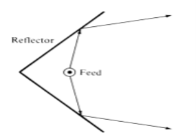
● It consists of two plane reflectors joined so as to form a corner. The feed element for a corner reflector is almost always a dipole or an array of collinear dipoles placed parallel to the vertex a distance s away.
|
Fig.4.10 Corner Reflector
● Greater bandwidth is obtained when the feed elements are cylindrical or biconical dipoles instead of thin wires.
● In many applications, especially when the wavelength is large compared to tolerable physical dimensions, the surfaces of the corner reflector are frequently made of grid wires rather than solid sheet metal , One of the reasons for doing that is to reduce wind resistance and overall system weight.
● The spacing (g) between wires is made a small fraction of a wavelength (usually g ≤ λ/10).For wires that are parallel to the length of the dipole, the reflectivity of the grid-wire surface is as good as that of a solid surface.
4.10.1. Practical design for Corner Reflector
● The length of the sides for reflectors with smaller included angles, the sides are made larger.
● For each reflector, there is an optimum feed-to-vertex spacing. If the spacing becomes too small, the radiation resistance decreases and becomes comparable to the loss resistance of the system which leads to an inefficient antenna. For very large spacing, the system produces undesirable multiple lobes, and it loses its directional characteristics.
● Increasing the size of the sides does not greatly affect the beam width and directivity, but it increases the bandwidth and radiation resistance.
● The analysis for the field radiated by a source in the presence of a corner reflector is facilitated when the included angle (α) of the reflector is α = π/n,
Where,
n is an integer (α = π,π/2,π/3,π/4, etc.).
For those cases (α = 180◦, 90◦, 60◦, 45◦,…)
● To maintain a given system efficiency, the spacing between the vertex and the feed element must increase as the included angle of the reflector decreases, and vice versa. For reflectors with infinite sides, the gain increases as the included angle between the planes decreases.
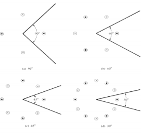
● The number of images, polarity, and position of each is controlled by the included angle of the corner reflector and the polarization of the feed element.
|
Figure 4.10.1. Corner reflector for different induced angles
4.10.2.90◦ Corner Reflector
● In most practical applications, the included angle formed by the plates is usually90◦.
● Because its radiation characteristics are the most attractive, it has become the most popular.
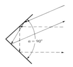
|
Fig.4.10.2. 90◦ Corner Reflector
● Because of its simplicity in construction, it has many unique applications.
● For example, if the reflector is used as a passive target for radar or communication applications, it will return the signal exactly in the same direction as it received it when its included angle is 90◦.
Key takeaways:
● Greater bandwidth is obtained when the feed elements are cylindrical or biconical dipoles instead of thin wires.
● In many applications, especially when the wavelength is large compared to tolerable physical dimensions, the surfaces of the corner reflector are frequently made of grid wires rather than solid sheet metal , One of the reasons for doing that is to reduce wind resistance and overall system weight.)
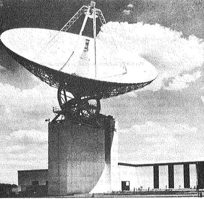
● This type of reflector has shape of paraboloid and hence it has properties of a parabola.
● The complete parabola has no endpoints. In this orientation, it extends infinitely to the left, right, and upward.
|
|
Figure 4.11. Parabolic Reflector
4.11.1. Parabolic antenna focal length
● One important element of the parabolic reflector antenna theory is its focal length. To ensure that the antenna operates correctly, it is necessary to ensure that the radiating element is placed at the focal point.
● To determine this it is necessary to know the focal length.
Focal length = f = 
● Where: f is the focal length D is the diameter of the reflector c is the depth of the reflector In addition to this the f/D ratio is important.
● As the f/D ratio is often specified along with the diameter, the focal length can be obtained very easily by multiplying its f/D ratio by the specified diameter D.
4.11.2. Geometric optics of parabolic reflector
|
Fig.4.11.2. Geometric optics of parabolic reflector
● It has been shown by geometrical optics that if a beam of parallel rays is incident upon a reflector whose geometrical shape is a parabola, the radiation will converge (focus) at a spot which is known as the focal point.
● In the same manner, if a point source is placed at the focal point, the rays reflected by a parabolic reflector will emerge as a parallel beam.
● Rays that emerge in a parallel formation are usually said to be collimated In practice, collimation is often used to describe the highly directional characteristics of an antenna even though the emanating rays are not exactly parallel.
|
|
(a) Curved (front-end) (b)curved(cassegrainfeed )
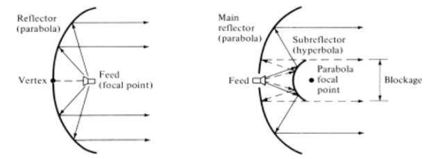
● Since the transmitter (receiver) is placed at the focal point of the parabola, the configuration is usually known as front fed.
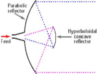
● Another arrangement that avoids placing the feed (transmitter and/or receiver) at the focal point is that as the Cassegrain feed.
● In cassegrain feed the incident parallel rays can be focused to a point by utilizing two reflectors.
● To accomplish this, the main (primary) reflector must be a parabola, the secondary reflector (sub reflector) a hyperbola, and the feed placed along the axis of the parabola usually at or near the vertex. Cassegrain used this scheme to construct optical telescopes.
● Cassegrain designs, employing dual-reflector surfaces, are used in applications where pattern control is essential, such as in satellite ground-based systems, and have efficiencies of 65–80%.
● They supersede the performance of the single-reflector frontfed arrangement by about 10%.
Key takeaways:
● This type of reflector has shape of paraboloid and hence it has properties of a parabola.
● The complete parabola has no endpoints. In this orientation, it extends infinitely to the left, right, and upward.)
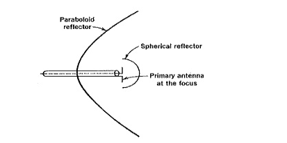
● The primary Parabolic Antenna is placed at the focus of the paraboloid for best results in transmission or reception. The direct radiation from the feed, which is not reflected by the paraboloid, tends to spread out in all directions and hence partially spoils the directivity.
● Several methods are used to prevent this, one of them being the provision of a small spherical reflector, as shown in Figure below, to redirect all such radiation back to the paraboloid.
● Another method is to use a small dipole array at the focus, such as a Yagi-Uda or an end-fire array, pointing at the paraboloid reflector.
|
Figure 4.12.1. Centre fed paraboloid with spherical shell
● Figure 4.12.2.. shows yet another way of dealing with the problem. A horn antenna pointing at the main reflector.
● It has a mildly directional pattern, in the direction in which its mouth points. Direct radiation from the feed antenna is once again avoided.
● It should be mentioned at this point that, although the feed antenna and its reflector obstruct a certain amount of reflection from the paraboloid when they are placed at its focus, this obstruction is slight indeed.
|
Figure 4.12.2. Paraboloid reflector with horn feed
● Another feed method, the Cassegrain feed, is named after an early-eighteenth-century astronomer and is adopted directly from astronomical reflecting telescopes.
|
Figure 4.12.3. Geometry of the Cassegrain feed
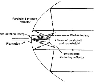
● One of its foci coincides with the focus of the paraboloid, resulting in the action shown (for transmission) in Figure 4.12.3.
● The rays emitted from the feed horn antenna are reflected from the paraboloid mirror. The effect on the main paraboloid reflector being the same as that of a feed antenna at the focus.
● The main reflector then collimates (renders parallel) the rays in the usual manner.
|
Figure 4.12.4. Paraboloid reflector with cassegrain feed
● The Cassegrain feed is used when it is desired to place the primary antenna in a convenient position and to shorten the length of the transmission line or waveguide connecting the receiver (or transmitter) to the primary.
● This requirement often applies to low-noise receivers, in which the losses in the line or waveguide may not be tolerated, especially over lengths which may exceed 30 m in large antennas.
● Another solution to the problem is to place the active part of the transmitter or receiver at the focus. With transmitters this can almost never be done because of their size, and it may also be difficult to place the RF amplifier of the receiver there.
● Hs is either because of its size or because of the need for cooling apparatus for very low-noise applications (in which case the RF amplifier may be small enough, but the ancillary equipment is not).
● Such placement of the RF amplifier causes servicing and replacement difficulties, and the Cassegrain feed is often the best solution.
● As shown in Figure 4.12.3., an obvious difficulty results from the use of a secondary reflector, namely, the obstruction of some of the radiation from the main reflector.
● This is a problem, especially with small reflectors, because the dimensions of the hyperboloid are determined by its distance from the horn primary feed and the mouth diameter of the horn itself, which is governed by the frequency used.
● One of the ways of overcoming this obstruction is by means of a large primary reflector (which is not always economical or desirable), together with a horn placed as close to the subreflector as possible.
● This is shown in Figure 4.12.4.and has the effect of reducing the required diameter of the secondary reflector. Vertically polarized waves are emitted by the feed, are reflected back to the main mirror by a hyperboloid consisting of vertical bars and have their polarization twisted by 90∘ by a mechanism at the paraboloid.
● The reflected waves are now horizontally polarized and pass the vertical bars of the secondary minor.
Key takeaways:
● Several methods are used for to feed. One of them being the provision of a small spherical reflector, to redirect all such radiation back to the paraboloid.
● Another method is to use a small dipole array at the focus, such as a Yagi-Uda or an end-fire array, pointing at the paraboloid reflector.
● The Cassegrain feed is used when it is desired to place the primary antenna in a convenient position and to shorten the length of the transmission line or waveguide connecting the receiver (or transmitter) to the primary.)
4.13.1. Introduction
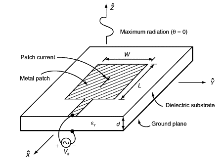
● Microstrip or patch antennas are becoming increasingly useful because they can be printed directly onto a circuit board.
● Microstrip antennas are becoming very widespread within the mobile phone market. Patch antennas are low cost, have a low profile and are easily fabricated.
|
|
|
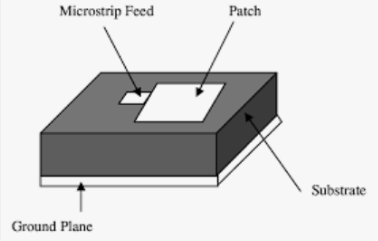
Figure 4.13.1. Microstrip antenna
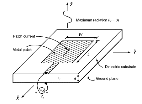
● The patch antenna, microstrip transmission line and ground plane are made of high conductivity metal (typically copper). The patch is of length L, width W, and sitting on top of a substrate (some dielectric circuit board) of thickness h with permittivity or dielectric constant.
● The thickness of the ground plane or of the microstrip is not critically important. Typically the height h is much smaller than the wavelength of operation, but should not be much smaller than 0.025 of a wavelength (1/40th of a wavelength) or the antenna efficiency will be degraded
4.13.2. Rectangular patch
● The figure below shows the rectangular patch.The radiation of the patch is perpendicular to the board on which it is placed. The dimension L is slightly less than half the free-space wavelength divided by the square root of the effective dielectric constant of the board.
● The feedline, in this case a microstrip line, is etched alongside the patch at the center of its width.
|
Figure 4.13.2.1.Rectangular patch
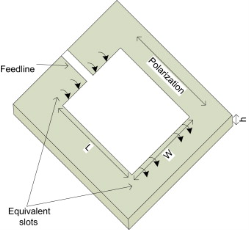
● The other two opposing edges that are W apart do not radiate so long as the feedline is at the center of the radiating edges. Thus, it can be concluded that a radiating patch can be modeled by two slots separated by a transmission line. Each slot can be represented by a parallel circuit of susceptance X and conductance G as shown by the equivalent circuit below.
● Note, however, that the circuit presented in Figure below does not model the mutual coupling present between the two radiating slotsj nor does it account for the radiation due to the non radiating edges of the patch.
● Due to these limitations, this model becomes unsuitable to analyze nonrectangular shapes and hence it is very limited in its application.
|
Figure 4.13.2.2. Equivalent circuit for the microstrip feedline
● A rectangular microstrip radiator can be modeled as an open cavity bounded by the patch and the ground plane.
● Assume the relative dielectric constant to be εr and the substrate thickness to be h,k then the total electric field in the leaky cavity can be expressed as
 (x,y) =
  cos
cos  cos
cos 
● Where the constant Cm,n depends on the feed location and L and W are the patch's resonant length and nonresonant width.
● The resonant frequency of a rectangular patch in the fundamental mode can be predicted using its dimensions and the relative dielectric constant, that is

Where, c is the speed of light, and  is the effective dielectric constant
 , where h/W > 1
● Note that for a very small h, the relationship for the resonant frequency becomes,

4.13.3. Circular Patch
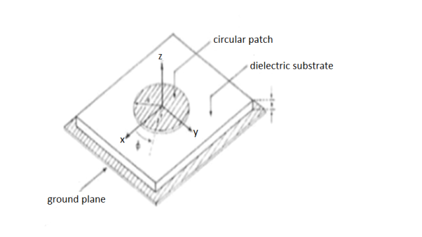
● The mode supported by the circular patch antenna can be found by treating the patch, ground plane and the material between the two as a circular cavity. The radius of the patch is the only degree of freedom to control the modes of the antenna .
● The antenna can be conveniently analyzed using the cavity model. The cavity is composed of two electric conductors at the top and the bottom to represent the patch and the ground plane and by a cylindrical perfect magnetic conductor around the circular periphery of the cavity.
|
Figure 4.13.3. Circular Patch
● The dielectric material of the substrate is assumed to be truncated beyond the extent of the patch. The field configuration within the cavity can be found using the vector potential.
● Circular Patch Radius and Effective Radius
Since the dimension of the patch is treated a circular loop, the actual radius of the patch is given by,
a = 
F = 
Above equation does not take into consideration the fringing effect. Since fringing makes the patch electrically larger, the effective radius of patch is used and is given by,
 = a
= a 
4.13.4. Feed Networks of microstrip antennas
● Microstrip antenna can be feed by variety of methods.
4.13.4.1. Microstrip Line feed
|
Figure 4.13.4.1. Microstrip Line feed
A conducting strip is connected to the edge of the patch. The feed can be etched to the substrate.
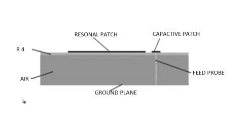
4.13.4.2. Capacitive Feeding
|
Figure 4.13.4.2. Capacitive Feeding
In this type of feeding the feeding is done to the smaller another patch instead of main radiating patch.
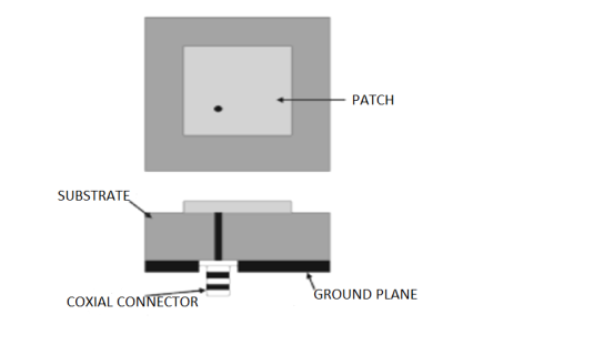
4.13.4.3. Coaxial Feeding
|
Figure 4.13.4.3. Coaxial Feeding
Coaxial feed or probe feed is the common technique used for feeding microstrip antennas.Thecenter conductor of the coaxial connector is soldered to the patch.
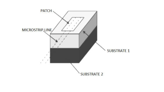
4.13.4.4. Proximity coupled feed
|
Figure 4.13.4.4. Proximity coupled feed
Fabrication of this feeding method is bit complicated. Two dielectric substrates are used in this technique. The microstrip patch is there at the upper surface of the upper dielectric substrate and the feed line is there between two substrate.
Key takeaways:
● Microstrip or patch antennas are becoming increasingly useful because they can be printed directly onto a circuit board.
● Microstrip antennas are becoming very widespread within the mobile phone market. Patch antennas are low cost, have a low profile and are easily fabricated.
● A rectangular microstrip radiator can be modeled as an open cavity bounded by the patch and the ground plane.
● The mode supported by the circular patch antenna can be found by treating the patch, ground plane and the material between the two as a circular cavity. The radius of the patch is the only degree of freedom to control the modes of the antenna.
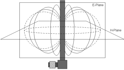
● Biconical Antennas have dipole like characteristics (e.g. circular directional pattern in the H-plane,"8"-shaped in the E-plane, fixed phase center, comparable gain), with an enormous wide bandwidth achieved by the double cone elements.
● One of the earliest and worldwide most popular biconical antenna designs is the BBA 9106 with balun VHA 9103 B. During the last years a growing need for expanded frequency ranges arised, which led to the design of biconical antennas reaching down to frequencies of 20 MHz and up to 18 GHz and above.
● A further increase of bandwidth was achieved with qualified 4:1 baluns, providing a typical gain increase of approx. 6 dB at the lower frequency range.
● The biconical elements can be mounted and dismounted within a few seconds providing perfect contact repeatability thanks to special clamping fixtures. A small wrench made of insulating material is supplied with the balun, it is tied to the balun head and thus always available whenever needed.
● Biconical antennas can be used for many applications, in which half-wave dipoles have been used traditionally. An enormous reduction of measurement time can be achieved, because the time consuming tuning of the antenna elements to the half wavelength is not needed.
Applications
● Broadband RX-antenna for emission testing (20-300 MHz)
● TX-antenna for immunity testing, especially at low frequencies
● Measurements of shielding effectiveness
● Evaluation of test sites e.g. anechoic rooms (FAC) and open area test sites (OATS)
● Passive field probe for immunity testing
4.14.1. Directional Antenna
● Biconical antennas (also known as Bowtie or Butterfly antennas) are broadband dipole antennas that are made up of two roughly conical conductive objects, nearly touching at their points.
● These antennas have dipole like characteristics, with a wider bandwidth achieved due to the double cone elements structure.
|
Figure 4.14.1. Directional AntennaRadiation pattern
● Bio-Conical antennas have an omni-directional radiation pattern in the H-plane similar to a dipole antenna. A coaxial feed is connected to the center of the antenna (where the two cones meet).
● The antenna can be mounted or dismounted very easily with perfect contact repeatability because of the clamping fixtures.
● Bioconical antennas can be used in a number of applications, typical applications include emission testing, immunity testing and measurement of shielding effectiveness.
● These antennas have replaced half-wave dipoles as biconical antennas allow continuous sweeps, which makes the discovery of anomalies at a site much easier.
4.14.2. Disk cone antenna
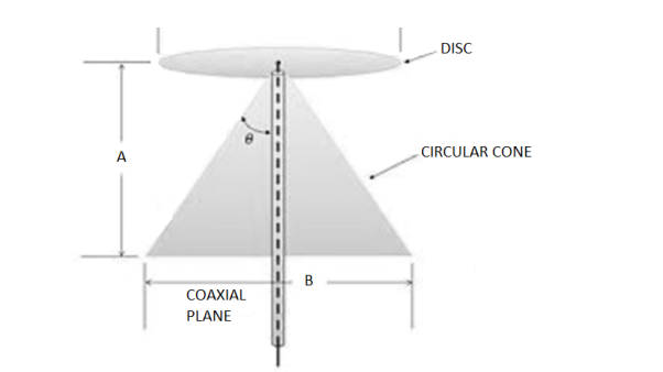
● It is a version of a biconical antenna in which one of the cones is replaced by a disc. It is usually mounted vertically, with the disc at the top and the cone beneath.
● Omnidirectional, vertically polarized and with gain similar to a dipole, it is exceptionally wideband, offering a frequency range ratio of up to approximately 10:1. The radiation pattern in the vertical plane is quite narrow, making its sensitivity highest in the direction of the horizon and rather less for signals coming from relatively close by.
|
Figure 4.14.2. Discone antenna
● The discone antenna has a useful frequency range of at least 10 to 1.When employed as a transmitting antenna, it is often less efficient than an antenna designed for a more limited frequency range.
● SWR (Standing wave ratio) is typically 1.5:1 or less over several octaves of frequency. A discone antenna consists of three main parts: the disc, the cone, and the insulator.
● The disc: The disc should have an overall diameter of 0.7 times a quarter wavelength of the antenna's lowest frequency. The antenna's feed point is at the center of the disc. It is usually fed with 50-ohm coaxial cable, with the center conductor connected to the disc, and the outer conductor to the cone.
● The cone: The length of the cone should be a quarter wavelength of the antenna's lowest operating frequency. The cone angle is generally from 25 to 40 degrees.
● The insulator: The disc and cone must be separated by an insulator, the dimensions of which determine some of the antenna's properties, especially on near its high frequency limit.
Construction Materials
● A discone may be made from solid metal sheet (often copper), which is practical for small indoor UHF antennas, such as for Wi-Fi.
● At lower frequencies a sufficient number of metal wires or rods in a spoke configuration is often used to approximate a solid surface. This simplifies construction and reduces wind loading.
● Mounted discone antenna designed for VHF and UHF coverage.
● The spokes may be made of stiff wire, brazing rods or even coat hanger wire.
● The optimal number of rods comprising the disc and cone is often quoted as being from 8 to 16.
Applications
● The discone's wideband coverage makes it attractive in commercial, military, amateur radio and radio scanner applications.
● The discone's inherently wideband nature permits it to broadcast undesirable spurious emissions from faulty or improperly filtered transmitters.
4.14.3. Bow Tie antenna
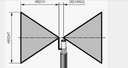
● A bowtie antenna uses triangular elements instead of straight rods as the antenna elements. The triangular elements sticking out on both sides of the antenna resemble a bow tie, hence the name.
● The “wings” of the antenna flare out symmetrically on both sides of the supporting beam. The two antennas nearly touch at the center.
|
Figure 4.14.3. Bow Tie antenna
● A bowtie antenna is sometimes called a butterfly antenna because it looks like a butterfly with its wings held open. When the bow tie elements have a metal bar that closes the antenna, it may be called a cat’s whisker antenna.
● The bowtie antenna is a type of UHF fan dipole antenna. Bow tie antennas may resemble log periodic antennas, but they are not considered LP antennas.
4.14.3.1.Advantages
● The bandwidth of the antenna is increased by using triangular elements over straight ones.
● Furthermore, the antennas often receive signals from a 60 degree angle, perfect for receiving signals from various sources. This is why bowtie antennas were common used with televisions receiving over the air broadcasts. They could receive a wide range of UHF signals, and it will do much better than a thin wire dipole antenna in this regard.
● This type of antenna is lighter in weight than a fan dipole antenna that connects the horizontal elements.
● The design also makes it more wind resistant. That’s a plus when you don’t want to have to climb on the roof to restore the antenna so you can watch the news.
● The design is made stronger by the metal bar that closes the bow tie, though that does add to its weight.
● This antenna design is cheap and easy to construct. That’s why rabbit ear antennas were so common on old televisions.
● The mesh reflector in the bowtie antenna is more efficient than other types of antennas such as yagi antennas.
4.14.3.2. Disadvantages
● Biconical antennas, including bowtie antennas, have poor transmitting efficiencies in the low end of their frequency range. A log periodic antenna is better in that regard.
● A bowtie antenna isn’t as well suited as a full biconical antenna in RF sniffing or RF signal detection.
Key takeaways:
● Biconical Antennas have dipole like characteristics (e.g. circular directional pattern in the H-plane,"8"-shaped in the E-plane, fixed phase center, comparable gain), with an enormous wide bandwidth achieved by the double cone elements.
● Disk cone antenna is a version of a biconical antenna in which one of the cones is replaced by a disc. It is usually mounted vertically, with the disc at the top and the cone beneath.
● A bowtie antenna uses triangular elements instead of straight rods as the antenna elements. The triangular elements sticking out on both sides of the antenna resemble a bow tie, hence the name.
● The “wings” of the antenna flare out symmetrically on both sides of the supporting beam. The two antennas nearly touch at the center.)
Principle
“The frequency independent antennas are fixed in size and operate over wide bandwidth with constant impedance, polarization and pattern. Rumsey’s principle states that the impedance & pattern of antenna is frequency independent if antenna size is specified in terms of angle”.
● Rumsey’s principle is applicable to the frequency independent antennas where the antenna size is specified in terms of angle and thus making the impedance and pattern independent of frequency.
● The frequency independent antennas are fixed in size and operate over wide bandwidth with constant impedance, polarization and pattern.
● A true frequency independent antenna must have a fixed physical size and operates on instantaneous basics over a wide bandwidth at a constant impedance, pattern.
Key takeaways:
● The frequency independent antennas are fixed in size and operate over wide bandwidth with constant impedance, polarization and pattern.
● Rumsey’s principle states that the impedance & pattern of antenna is frequency independent if antenna size is specified in terms of angle”.)
● For commercial purpose and to tune over a range of frequencies, log-periodic antenna is used. A Log-periodic antenna is that whose impedance is a logarithamically periodic function of frequency.
4.16.1. Frequency Range
● The frequency range, in which the log-periodic antennas operate is around 30 MHz to 3GHz which belong to the VHF and UHF bands.
4.16.2. Construction & Working of Log-periodic Antenna
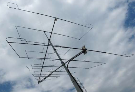
● The construction and operation of a log-periodic antenna is similar to that of a Yagi-Uda antenna. The main advantage of this antenna is that it exhibits constant characteristics over a desired frequency range of operation.
● It has the same radiation resistance and therefore the same SWR. The gain and front-to-back ratio are also the same.
|
Figure 4.16. Log Periodic Antenna
● The image shows a log-periodic antenna.With the change in operation frequency, the active region shifts among the elements and hence all the elements will not be active only on a single frequency. This is its special characteristic.
● There are several type of log-periodic antennas such as the planar, trapezoidal, zig-zag, V-type, slot and the dipole. The mostly used one is log-periodic dipole array, in short, LPDA.
4.16.3. Radiation Pattern
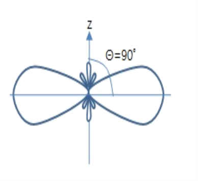
● The Radiation pattern of log-periodic antenna can be of uni-directional or bi-directional, depending upon the log periodic structures.
● For uni-directional Log-periodic antenna, the radiation towards shorter element is of considerable amount, whereas in forward direction, it is small or zero.
|
Figure 4.16.3. Radiation Pattern
4.16.4. Advantages
The following are the advantages of Log-periodic antennas −
● The antenna design is compact.
● Gain and radiation pattern are varied according to the requirements.
4.16.5. Disadvantages
The following are the disadvantages of Log-periodic antennas −
● External mount.
● Installation cost is high.
4.16.6. Applications
The following are the applications of Log-periodic antennas −
● Used for HF communications.
● Used for particular sort of TV receptions.
● Used for all round monitoring in higher frequency bands.
Key takeaways:
● For commercial purpose and to tune over a range of frequencies, log-periodic antenna is used.
● A Log-periodic antenna is that whose impedance is a logarithamically periodic function of frequency.)
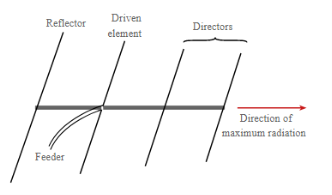
● Composite Yagi Uda comer log periodic array concept is used for extending the frequency bandwidth of the basic Yagi-Uda antenna by employing log periodic principles.
● Log-periodic antennas are designed to work across a wide range of frequencies; Yagi-Uda is optimised for one frequency. Yagi-Uda will give higher gain at its optimal frequency; log-periodic will have lower gain across a wide range of frequencies.
|
Figure 4.17.1. Yagi uda antenna
● Reflectors behind the first one make no noticeable different to the antenna performance. However many designs use reflectors consisting of a reflecting plate, or a series of parallel rods simulating a reflecting plate. This gives a slight improvement in performance, reducing the level of radiation or pick-up from behind the antenna, i.e. in the backwards direction. Tis can help in reducing the levels of interference received.
|
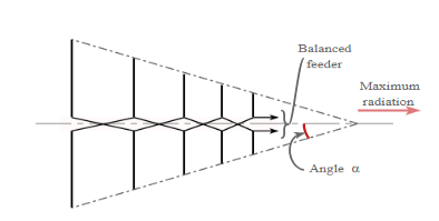
Figure 4.17.2. Log periodic dipole array
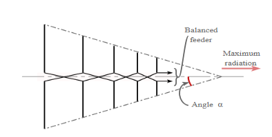
● The log periodic dipole array consists of a number of dipole elements. These progressively reduce in size from the back to the front – the direction of maximum radiation is from the smaller front.
● Each dipole element of the LPDA is fed, but the phase is reversed between adjacent dipole elements – this ensures that the signal phasing is correct between the different elements. It also means that a feeder is required along the length of the antenna. Normally this is arranged so that it forms part of the mechanical structure of the array.
● Not all the antenna array is active at any given frequency. The active region, i.e. the sections of the antenna that are contributing to the transmission or reception vary with frequency, and only about three may really contribute to the radiation at any given frequency. There is also a smooth transition of the active region of the LPDA along the array as the frequency of operation changes.
● The element at the back of the array where the elements are the largest is a half wavelength at the lowest frequency of operation - the longest element acts as a half wave dipole at the lowest frequency. The element spacing also decrease towards the front of the array where the smallest elements are located. The upper frequency is a function of the length of the shortest element.
Key takeaways:
● Composite Yagi Uda comer log periodic array concept is used for extending the frequency bandwidth of the basic Yagi-Uda antenna by employing log periodic principles.
● Log-periodic antennas are designed to work across a wide range of frequencies; Yagi-Uda is optimised for one frequency. Yagi-Uda will give higher gain at its optimal frequency; log-periodic will have lower gain across a wide range of frequencies.
● The log periodic dipole array consists of a number of dipole elements. These progressively reduce in size from the back to the front – the direction of maximum radiation is from the smaller front.)
References
- K. D. Prasad, “Antenna and Wave Propagation”, Satya Prakashan.
- “Antennas and Wave Propagation” by A R Harish and M Sachidananda.
- “Antenna and Wave Propagation” by Sisir Das and Annapurna Das.
