UNIT-6
Sky Wave Propagation
● It is a type of radio wave propagation. The wave which propagate through atmosphere and are reflected back by the ionosphere of earth's atmosphere is called as sky wave propagation.
● It is either the reflected or refracted back waves to the earth from the ionosphere which is an electrically charged layer of the upper atmosphere.
● Medium and shortwave frequencies can be refracted back to earth which is beyond the horizon which makes them useful in the transcontinental transmission of the waves.
● These waves go from transmitter antenna to receiver antena travelling through sky. The sky waves are of practical importance at medium and high frequency for very long distance radio communication.
● The ionosphere is the ionized part of Earth’s upper atmosphere from about 48 km (30 mi) to 965 km (600 mi) altitude, a region that includes the thermosphere and parts of the mesosphere and exosphere. The ionosphere is ionized by solar radiation. It plays an important role in atmospheric electricity and forms the inner edge of the magnetosphere. It has practical importance because, among other functions, it influences radio propagation to distant places on the Earth.
● The ionosphere is a shell of electrons and electrically charged atoms and molecules that surrounds the Earth, stretching from a height of about 50 km (31 mi) to more than 1,000 km (620 mi). It exists primarily due to ultraviolet radiation from the Sun.
|
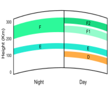
Figure 6.2. Structural Details of Ionosphere
6.2.1. Layers of Ionization
● At night the F layer is the only layer of significant ionization present, while the ionization in the E and D layers is extremely low. During the day, the D and E layers become much more heavily ionized, as does the F layer, which develops an additional, weaker region of ionisation known as the F1 layer.
● The F2 layer persists by day and night and is the main region responsible for the refraction and reflection of radio waves.
● The D layer is the innermost layer, 60 km (37 mi) to 90 km (56 mi) above the surface of the Earth. Ionization here is due to Lyman series-alpha hydrogen radiation at a wavelength of nanometre (nm) ionizing nitric oxide (NO).
● In addition, high solar activity can generate hard X-rays (wavelength < 1 nm) that ionize N2 and O2. Recombination rates are high in the D layer, so there are many more neutral air molecules than ions.
● Medium frequency (MF) and lower high frequency (HF) radio waves are significantly attenuated within the D layer, as the passing radio waves cause electrons to move, which then collide with the neutral molecules, giving up their energy.
● Lower frequencies experience greater absorption because they move the electrons farther, leading to greater chance of collisions. This is the main reason for absorption of HF radio waves, particularly at 10 MHz and below, with progressively less absorption at higher frequencies.
● This effect peaks around noon and is reduced at night due to a decrease in the D layer's thickness; only a small part remains due to cosmic rays. A common example of the D layer in action is the disappearance of distant AM broadcast band stations in the daytime.
● During solar proton events, ionization can reach unusually high levels in the D-region over high and polar latitudes. Such very rare events are known as Polar Cap Absorption (or PCA) events, because the increased ionization significantly enhances the absorption of radio signals passing through the region.
● In fact, absorption levels can increase by many tens of dB during intense events, which is enough to absorb most (if not all) transpolar HF radio signal transmissions. Such events typically last less than 24 to 48 hours.
● The E layer is the middle layer, 90 km (56 mi) to 150 km (93 mi) above the surface of the Earth.
● Ionization is due to soft X-ray (1–10 nm) and far ultraviolet (UV) solar radiation ionization of molecular oxygen (O2). Normally, at oblique incidence, this layer can only reflect radio waves having frequencies lower than about 10 MHz and may contribute a bit to absorption on frequencies above.
● However, during intense sporadic Eevents, the Es layer can reflect frequencies up to 50 MHz and higher. The vertical structure of the E layer is primarily determined by the competing effects of ionization and recombination.
● At night the E layer weakens because the primary source of ionization is no longer present. After sunset an increase in the height of the E layer maximum increases the range to which radio waves can travel by reflection from the layer.
● The Es layer (sporadic E-layer) is characterized by small, thin clouds of intense ionization, which can support reflection of radio waves, rarely up to 225 MHz.
● Sporadic-E events may last for just a few minutes to several hours. Sporadic E propagationmakes VHF-operating radio amateurs very excited, as propagation paths that are generally unreachable can open up. There are multiple causes of sporadic-E that are still being pursued by researchers.
● This propagation occurs most frequently during the summer months when high signal levels may be reached. The skip distances are generally around 1,640 km (1,020 mi).
● Distances for one hop propagation can be anywhere from 900 km (560 mi) to 2,500 km (1,600 mi). Double-hop reception over 3,500 km (2,200 mi) is possible.
● The F layer or region, also known as the Appleton–Barnett layer, extends from about 150 km (93 mi) to more than 500 km (310 mi) above the surface of Earth.
● It is the layer with the highest electron density, which implies signals penetrating this layer will escape into space. Electron production is dominated by extreme ultraviolet (UV, 10–100 nm) radiation ionizing atomic oxygen. T
● he F layer consists of one layer (F2) at night, but during the day, a secondary peak (labelled F1) often forms in the electron density profile. Because the F2 layer remains by day and night, it is responsible for most skywave propagation of radio waves and long distance high frequency (HF, or shortwave) radio communications.
Above the F layer, the number of oxygen ions decreases and lighter ions such as hydrogen and helium become dominant. This region above the F layer peak and below the plasmasphere is called the topside ionosphere.
Key takeaways :
● The ionosphere is the ionized part of Earth’s upper atmosphere from about 48 km (30 mi) to 965 km (600 mi) altitude, a region that includes the thermosphere and parts of the mesosphere and exosphere.
● The ionosphere is ionized by solar radiation. It plays an important role in atmospheric electricity and forms the inner edge of the magnetosphere.
● It has practical importance because, among other functions, it influences radio propagation to distant places on the Earth.
● The ionosphere is a shell of electrons and electrically charged atoms and molecules that surrounds the Earth, stretching from a height of about 50 km (31 mi) to more than 1,000 km (620 mi). It exists primarily due to ultraviolet radiation from the Sun.)
|
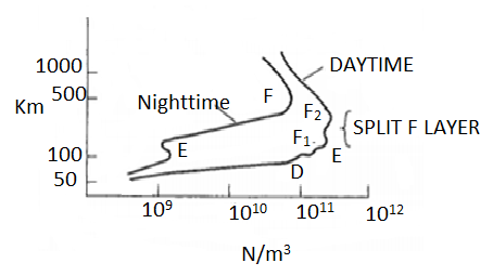
Figure 6.3.1. Electron density as a function of altitude and various ionospheric layers
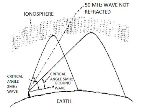
● Radio waves below 40 MHz are significantly affected by the ionosphere, primarily because radio waves in this frequency range are effectively reflected by the ionosphere.
● The E and F layers are the most important for this process. For frequencies beyond 40 MHz, the wave tend to penetrate through the atmosphere versus being reflected. The major usefulness of the ionosphere is that the reflections enable wave propagation over a much larger distance than would be possible with line-of-sight or even atmospheric refraction effects.
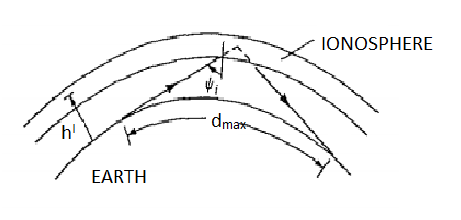
● This is shown graphically in Figure 2. The skip distance dmax can be very large, allowing very large communication distances. This is further enhanced by multiple reflections between the ionosphere and the ground, leading to multiple skips.
● This form of propagation allows shortwave and amateur radio signals to propagate worldwide. Since the D layer disappears at night, the best time for long-range communications is at night, since the skip distance is larger as the E, and F regions are at higher altitudes.
● The ionosphere exists between about 90 and 1000 km above the earth’s surface. Radiation from the sun ionizes atoms and molecules here, liberating electrons from molecules and creating a space of free electron and ions.
● Subjected to an external electric field from a radio signal, these free and ions will experience a force and be pushed into motion. However, since the mass of the ions is much larger than the mass of the electrons, ionic motions are relatively small and will be ignored here.
|
. Figure 6.3.2. A single skip of radio wave using ionosphere
● Free electron densities on the order of 1010 to 1012 electrons per cubic metre are produced by ionization from the sun’s rays. Layers of high densities of electrons are given special names called the D, E, and F layers.
● During the day the F layer splits into two layers called the F1 and F2 layers, while the D layer vanishes completely at night.
Key takeaways:
● Radio waves below 40 MHz are significantly affected by the ionosphere, primarily because radio waves in this frequency range are effectively reflected by the ionosphere.
● The E and F layers are the most important for this process. For frequencies beyond 40 MHz, the wave tend to penetrate through the atmosphere versus being reflected.
● The major usefulness of the ionosphere is that the reflections enable wave propagation over a much larger distance than would be possible with line-of-sight or even atmospheric refraction effects.)
● When high-frequency signals enter the ionosphere at a low angle they are bent back towards the earth by the ionized layer.
● When operating at frequencies just below the MUF, losses can be quite small, so the radio signal may effectively "bounce" or "skip" between the earth and ionosphere two or more times.
● If the ionization is not great enough, the wave only curves slightly downwards, and subsequently upwards as the ionization peak is passed so that it exits the top of the layer only slightly displaced. The wave then is lost in space.
● To prevent this a lower frequency must be chosen.
|
Figure 6.4. Reflection by the Ionosphere
● Ionospheric reflection occurs when certain radio waves strike a thin, highly ionized layer in the ionosphere. Although the radio wave are actually refracted, some may be bent back so rapidly that they appear to be reflected.
● For Ionospheric reflection to occur the highly ionized layer can be approximately no thicker than one wavelength of the wave since the ionized layers are often several miles thick
● Ionospheric reflection mostly occurs at long wavelengths
Key takeaways:
● When high-frequency signals enter the ionosphere at a low angle they are bent back towards the earth by the ionized layer.
● When operating at frequencies just below the MUF, losses can be quite small, so the radio signal may effectively "bounce" or "skip" between the earth and ionosphere two or more times.)
● When a radio wave is transmitted into an ionized layer, refraction, or bending of the wave, occurs.
● Refraction is caused by an abrupt change in the velocity of the upper part of a radio wave as it strikes or enters a new medium.
● The amount of refraction that occurs depends on three main factors: ⎫the density of ionization of the layer, the frequency of the radio wave, and ⎫the angle at which the wave enters the layer.
● When a radio wave is transmitted into an ionized layer, refraction, or bending of the wave, occurs. Refraction is caused by an abrupt change in the velocity of the upper part of a radio wave as it strikes or enters a new medium.
● The amount of refraction that occurs depends on three main factors: (1) the density of ionization of the layer, (2) the frequency of the radio wave, and (3) the angle at which the wave enters the layer.
Key takeaways :
● When a radio wave is transmitted into an ionized layer, refraction, or bending of the wave, occurs.
● Refraction is caused by an abrupt change in the velocity of the upper part of a radio wave as it strikes or enters a new medium.
● The amount of refraction that occurs depends on three main factors:
1.the density of ionization of the layer
2.the frequency of the radio wave, and
3.the angle at which the wave enters the layer.)
● It is also known as Propagation Path.
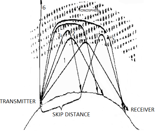
● The path that a refracted wave follows to the receiver depends on the angle at which the wave strikes the ionosphere.
● It may also, reach the receiving antenna over a path involving more than one layer, by multiple hops/skip between the ionosphere and Earth, or by any combination of these paths.
● The various angles at which RF waves strikes the layer are represented by dark lines and designated as rays 1 through 6.
|
Figure 6.6. Ray path with varying angles of incidence
● Ray 1 -- the propagation path is long.
● Ray 2 and Ray 3-- the rays penetrate deeper into the layer but the range of these rays decreases.
● When a certain angle is reached (Ray 3), the refraction of the ray is first returned to Earth , its second refraction from the ionospheric layer.
● Ray 4 and Ray 5--the RF energy penetrates the central area of maximum ionization of the layer. These rays are refracted rather slowly and are eventually returned to Earth at great distances.
● Ray 6-- the ray is not returned at all, but passes on through the layer.
● It is also known as Propagation Path. The path that a refracted wave follows to the receiver depends on the angle at which the wave strikes the ionosphere.
● It may also, reach the receiving antenna over a path involving more than one layer, by multiple hops/skip between the ionosphere and Earth, or by any combination of these paths.)
● The critical frequency is an important figure that gives an indication of the state of the ionosphere and the resulting HF propagation. It is obtained by sending a signal pulse directly upwards. This is reflected back and can be received by a receiver on the same site as the transmitter.
● The pulse may be reflected back to earth, and the time measured to give an indication of the height of the layer. As the frequency is increased a point is reached where the signal will pass right through the layer, and on to the next one, or into outer space. The frequency at which this occurs is called the critical frequency.
● Critical frequency is defined as the maximum frequency at which the total internal reflection takes place from the ionosphere. The mathematical representation is given as: 
Where,
fc: critical frequency in Hz
Nmax: maximum electron density per m3
● The mathematical representation of critical frequency as a function of MUF is: 
Where,
fc: critical frequency in Hz
MUF: maximum usable frequency
Ө: angle of incidence
● Critical frequency varies depending upon atmospheric conditions, time of the day and the angle of fire of the radio waves by the antenna.
Key takeaways:
● Critical frequency is defined as the maximum frequency at which the total internal reflection takes place from the ionosphere.
● The mathematical representation is given as:
● When a signal is transmitted using HF propagation, over a given path there is a maximum frequency that can be used. This results from the fact that as the signal frequency increases it will pass through more layers and eventually travelling into outer space.
● As it passes through one layer it may be that communication is lost because the signal then propagates over a greater distance than is required. Also when the signal passes through all the layers communication will be lost.
● The frequency at which radio communications just starts to fail is known as the Maximum Usable Frequency (MUF). As a rule of thumb it is generally three (for the F region) to five (for the E region) times the critical and it is true for low angles of incidence, although more exact methods are available for determining this figure.
● It is possible to calculate the relationship more exactly:

Where:
MUF = Maximum Usable Frequency
CF = critical frequency
θ = the angle of incidence.
● The factor sec θ is called the MUF factor and it is a function of the path length if the height layer is known.
● This is the maximum usable frequency, MUF that would permit acceptable operation of a radio service between given terminals under specific working conditions.
● This form of MUF has the emphasis on the operational acceptability of the circuit. It means that factors such as the antenna, power levels and such like are considered and gives an indication regarding the possibility of real communication at a given station.
Key takeaways:
● The frequency at which radio communications just starts to fail is known as the Maximum Usable Frequency (MUF).
● As a rule of thumb it is generally three (for the F region) to five (for the E region) times the critical and it is true for low angles of incidence. )
● As the frequency of a transmission is reduced further reflections from the ionosphere may be needed, and the losses from the D layer increase. These two effects mean that there is a frequency below which radio communications between two stations will be lost. In fact the Lowest Usable Frequency (LUF) is defined as the frequency at below which the signal falls below the minimum strength required for satisfactory reception.
● From this it can be seen that the LUF is dependent upon the stations at either end of the path. Their antennas, receivers, transmitter powers, the level of noise in the vicinity, and so forth all affect the LUF. The type of modulation used also has an effect, because some types of modulation can be copied at lower strengths than others.
● In other words the LUF is the practical limit below which communication cannot be maintained between two particular radio communications stations.
● If it is necessary to use a frequency below the LUF then as a rough guide a gain of 10dB must be made to decrease the LUF by 2 MHz. This can be achieved by methods including increasing the transmitter powers, improving the antennas, etc.
● It is found that the LUF actually increases in periods of high solar activity. This is arises because of the increased levels of solar radiation that give rise to higher levels of ionisation in the D layer.
● His in turn increases the level of attenuation introduced by this layer. This means that at the peak of the sunspot cycle there is degradation in the performance of the low frequency bands for long distance communications.
Key takeaways:
● The Lowest Usable Frequency (LUF) is defined as the frequency at below which the signal falls below the minimum strength required for satisfactory reception.
● From this it can be seen that the LUF is dependent upon the stations at either end of the path. Their antennas, receivers, transmitter powers, the level of noise in the vicinity, and so forth all affect the LUF.)
● To be able to send signals to a given location there are likely to be several different paths that can be used. Sometimes it may be possible to use the either the E or the F layers, and sometimes a signal may be reflected first off one and then the other. However it is still possible to choose a frequency from a variety of options to help making contact with a given area.
● In general the higher the frequency, the better. This is because the attenuation caused by the D layer is less. Although signals may be able to travel through the D layer they may still suffer significant levels of attenuation.
● As the attenuation reduces by a factor of four for doubling the frequency in use this shows how significant this can be.
● Also by increasing the frequency it is likely that a higher layer in the ionosphere will be used. This may result in fewer reflections being required.
● As losses are incurred at each reflection and each time the signal passes through the D layer, using a higher frequency obviously helps.
● When using the higher frequencies it is necessary to ensure that communications are still reliable. In view of the ever-changing state of the ionosphere a general rule of thumb is to use a frequency that is about 20% below the MUF.
● This should ensure that the signal remains below the MUF despite the short-term changes. However it should be remembered that the MUF will change significantly according to the time of day, and therefore it will be necessary alter the frequency periodically to take account of this.
Key takeaways:
● To be able to send signals to a given location there are likely to be several different paths that can be used.
● Sometimes it may be possible to use the either the E or the F layers, and sometimes a signal may be reflected first off one and then the other.
● However it is still possible to choose a frequency from a variety of options to help making contact with a given area.)
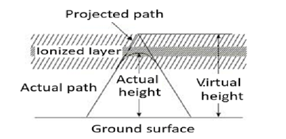
● When a wave is refracted, it is bent down gradually, but not sharply. However, the path of incident wave and reflected wave are same if it is reflected from a surface located at a greater height of this layer. Such a greater height is termed as virtual height.
|
Figure 6.11. Virtual Height
● The figure clearly distinguishes the virtual height (height of wave, supposed to be reflected) and actual height (the refracted height). If the virtual height is known, the angle of incidence can be found.
Key takeaways:
● When a wave is refracted, it is bent down gradually, but not sharply. However, the path of incident wave and reflected wave are same if it is reflected from a surface located at a greater height of this layer. Such a greater height is termed as virtual height.
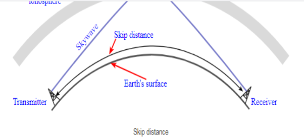
● Skip distance is defined as the minimum distance from the earth’s surface and the point from where the radio signal is been transmitted. For a flat earth skip distance is given as:
● DSKIP = 2h
Where,
DSKIP: skip distance
h: height at which reflection happens
fMUF: maximum usable frequency
fc: critical frequency
|
● So, The skip distance is the distance over the Earth's surface between the point where a radio signal is transmitted, and the point where it is received having travelled to the ionosphere, and been refracted back by the ionosphere.
Key takeaways:
● Skip distance is defined as the minimum distance from the earth’s surface and the point from where the radio signal is been transmitted.
● For a flat earth skip distance is given as: DSKIP = 2h )
)
● Relation between MUF & Skip distance for Flat Earth The ionosphere has many tiny layers , for atmospheric refraction.
 Sin
Sin  =
=  Sin
Sin 1 =
1 = Sin
Sin  ……
…… Sink
Sink
● The condition for the wave to return to earth is to have total internal reflection (TIR), which begins when the refracted angle ,θr is 900 .
● If this happens at the k th layer,
 Sin
Sin  =
=  Sin 900 =
● And since, 
Sin  =
= 
● Sin2 =
=  =
= 
 =
= 
● Critical frequency
For a given angle of incidence θi and frequency f, the minimum electron density required to achieve TIR is
 Sin2
Sin2 = 1-
= 1- 
● Where,
N is the electron density (m-3),
 is the mass of electron at rest,
  =9.109
 kg
kg
w is the angular frequency of the wave, w = 2Пf
 is the magnitude of electron charge,
  = 1.6021
  C
C
 is the permittivity of free space.
 F/m
F/m
● If the maximiumelectron density present is Nmax, refraction of the wave at normal incidence (θi=0 &sinθi = 0), the only possible way for the wave to be totally internally reflected is if ε= 0.
● This requires the frequency to be less than the critical frequency f c , given by
 = Sin2
 = 1-
= 1-  = 1-
= 1- 
If  = 0,
= 0,  = 1
= 1
 = 9
= 9
Refractive index as the function of frequency
 = 1 -
= 1 -  = 1 -
= 1 -  = 1 -
= 1 - 
 = 1 –
= 1 –  ,
,


● For MUF ,
 =900,
=900,  =
=  where 900= 1
 = 1- sin2
 = cos2
 =
=  =
= 
 =
=  = 9
= 9
This value of  is called the maximum usable frequency, and is less than 40 MHz, and can be as low as 25-30 MHz.
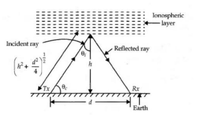
● Skip distance
|
Figure 6.13.2. Skip distance
Cos  =
= 
Cos  =
= 
 =
= 
 =
=  = =(
= =(  =
= 
 + 1
+ 1
 =
= 
 =
=  , h =
, h = , d=
, d=  ,
,
 = 2h
= 2h
h is the height of the layer d is the skip distance on the flat Earth’s surface.
( Key takeaways :Critical frequency is  = 9
= 9 =
=  = 9
= 9 ,
,  = 2h
= 2h )
)
|
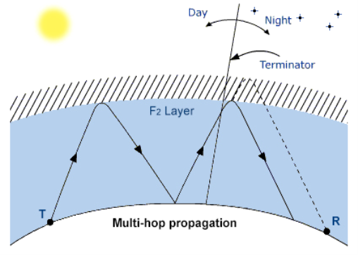
Figure 6.14. Multi hop propagation
● There is a way to exceed the maximum distance allowed by F2 layer is the multi hop propagation.
● When conditions are in favour of DX, bands open down to QRP station, instead of working a near station in doing only one jump or a single hop via F2 layer,we can reach DX stations in doing several hops and break the skip distance over 1500 km on the higher frequencies.
● In using a very low incidence angle, if the first signal reflects well to the upper layers of the ionosphere and then impacts the ground far from your home, hop after hop this multi hop propagaton allows communications with stations located on the other side of earth
Key takeaways:
● There is a way to exceed the maximum distance allowed by F2 layer is the multi hop propagation.
● When conditions are in favour of DX, bands open down to QRP station, instead of working a near station in doing only one jump or a single hop via F2 layer, we can reach DX stations in doing several hops and break the skip distance over 1500 km on the higher frequencies.)
- Not limited by the curvature of earth.
- Also known as skip wave/ ionospheric wave / hop wave.
- Frequency range 2 to 30 MHz.
- It includes multiple hops between earth and ionosphere.
- It is ionised by solar radiation.
- Does not require high transmission power.
- Does not require large antennas
References
- Atmospheric Effects on Electromagnetic Systems, Module 3: HF and Lower Frequency Radiation.
- Navy Electricity and Electronics Training Series Module 10: Wave Propagation, Transmission Lines, and Antennas (NEETS MOD 10).
- BOM Space Weather Services: Introduction to HF Radio Propagation.
