UNIT - 1
Modelling in the Frequency domain
1.1.1 Open loop systems:
This is the loop of control system without any feedback. In this the control action is not dependent on the desired output.
|
Fig. 1 open loop control system
Example of open Loop systems are the traffic signals, Automatic washing machine and in fields control d.c. motor.
1.1.2 Closed loop systems:
This is a type of control system with feedback. In this type of system, the control action is dependent on the desired output.
|
Fig 2 Closed Loop control system
The error signal is again fed to controller to the error and get desired output.
Key takeaway:
- The open loop systems are without feedback.
- The closed loop systems use feedback.
It is a technique for solving differential equations. The time domain differential equations are transformed into algebraic equation of frequency domain. After solving the algebraic equation in frequency domain, the result then is finally transformed to time domain form to achieve the ultimate solution of the differential equation.
The Laplace Transform is given as
F(s)= |
The advantages of Laplace Transform are:
1) It is systematic.
2) It gives total solution (transient and sustained solution) in one operation.
3) The initial conditions are automatically specified in the transformed equations.
There are many functions which do not have Laplace Transforms. These functions are not generally used in analysis of linear systems. But some conditions can be defined to get Laplace transformation of such functions. The Dirichlet condition defines the necessary condition for transformation of some functions such as:
a) The function should be continuous. The function should be single-valued.
b) The function must be of exponential order.
Properties of Laplace Transform:
- Linearity Property:
If f1(t) and f2(t) are two functions of time. Then, in domain of convergence L[a f1(t)+b f2(t)]=a =aF1(s)+bF2(s) |
- Differentiation Property:
If x(t) is function of atime, then Laplace transform of nth derivative is given as
|
- Integration Property:
The Laplace of nth order integral is given as
L[ L[f-n(t)]= As L[f-n(t)]= |
Inverse Laplace transforms
The Laplace inverse of any function H(s) is given by L-1 H(s) = h(t) Properties of Inverse Laplace transform are Linearity property L-1 {aH1(s)+b H2(s)} = ah1(t)+bh2(t) Shifting property L-1 H(s) = h(t) L-1 H(s-a) = eat h(t) If L-1 H(s) = h(t) Then, L-1 [H(s)/s] = If L-1 H(s) = h(t) L-1 e-at H(s) = u(t-a). h(t-a) |
Key takeaway
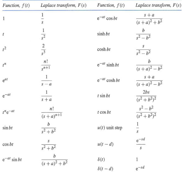
Laplace Transform of some common functions
|
1.3.1 Electrical System
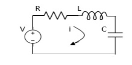
Applying Kirchoff’s voltage Law V= Ri +Ldi/dt +1/c V= Rdq/dt + L d2q/dt2+q/c Now By kirchoff’s current low I= V/R+ 1/L But V= dø/dt I= 1/R dø/dt + 1/L ø+cd2ø/dt2 But v= dø/dt I= 1/R dø/dt+ 1/L. ø+c d2ø/dt2 |
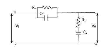
Example-2 For the given mechanical system below draw the analogus system (force. Voltage) & find V0(s)/V1(s)
Soln.
Let Z1 = R2 11 1/c2 =R2*1/c2s/R2+1/c2s Z1= R2/1+R2c2s Let Z2 = R1+1/c1s Z2= 1+R1c1s/c1s V0(s)/vi(s) = z2/z1+z2 = 1+R1c1s/c1s/R2/1+R2c2s+1+R1c1s/c1s V0(s)/v0(s) =(c1+R1c1s) (1+R2c2s)/R2c1s+1+sR1c1s2R1R2c1c2 |
1.3.2 Mechanical System
(a) Translational system
(b) Rotational system
Translational system
The motion that takes place along a straight line is called translational the forces that resist motion are
- Inertia: A body with mass ‘N’ acceleration ‘a’ will produce inertia
fm(t)= malt N’ acceleration ‘a’ will produce inertia fm(t)= M a(t) In terms of velocity Fm(t) = M dv(t)/dt In terms of displacement Fm(t)= Md2/dt2µt |
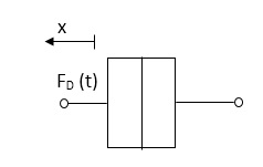
2. Damping force: The damping force is proportional to velocity for vis case function
Fig 3 Damping Force F0(t) = B(t) = B dx(t) /dt B Damping coefficient N/M sec |
3. Spring force: A spring stores potential energy. The releasing force of a string is proportional to the displacement.
Constant |
Fk(t)  x(t)
x(t)
Fk(t) = k x (t)
Fk(t) = k 
K = string constant N/m.
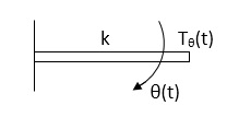
(b)Rational System: - The motion of a body about a fixed axis is called as Rotational Motion The types of torques which can resist the motion are
i) Inertial Torque: - The inertial torque is the product of moment of inertia I and angular acceleration.
TI(t) = J TI(t) = Jd/dt w(t) TI(t) = Jd2ø(t)/dt2(N-m) W (t) – Angular velocity Ø(t) = Angular displacement |
(ii) Damping Torque: - it is product of damping efficient B and angular velocity
T0 (t) = B w(t) T0(t) = B d/dt ø(t) |
(iii) Spring Torque: - It is the product of torsional stiffness and angular displacement
Fig 5 Rotational Spring Constant Tø(t) = k ø(t) K = N.m/rad |
D’Alembert’s Principle
For anybody, the algebraic sum of externally applied forces and the forces resisting motion in any given direction is zero.
Ex.
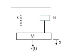
|
Fig 6 Mechanical System
In above figure applying D’Alemberts principle to write the equation of motion
As force f(t) acts downwards all other forces (of k,B,x)acts Opposite to it to considering f(t) as the and all other forces negative.
f(t)- M d2x(t)/dt2+B dx(t)/dt +x(t) |
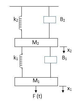
Example-1 Draw the free body diagram and write the differential equation for system below.
|
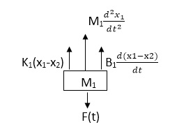
Soln: The free body diagram for M1 will be
|
Fig 8 FBD for Mechanical System
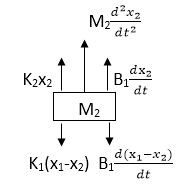
F(t) = M1 d2/dt2x1+ B1 d/dt (x1-x2)+ k1(x1-x2) Similarly for M2we have
Fig 9 FBD for Mechanical System K1(x1-x2) + B1d/dt(x1-x2) = k2x2+M2d2/dt2+B2dx2/dt |
1.3.3 Thermal
Thermal systems are those that involve the transfer of heat from one substance to another. The model of thermal systems is obtained by using thermal resistance and capacitance which are the basic elements of the thermal system. The thermal resistance and capacitance are distributed in nature. But for simplicity in analysis lumped parameter models are used.
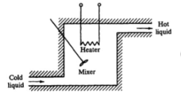
Consider a simple thermal system shown in the below figure. Let us assume that the tank is insulated to eliminate heat loss to the surrounding air, there is no heat storage in the insulation and liquid in the tank is kept at uniform temperature by perfect mixing with the help of a stirrer. Thus, a single temperature is used to describe the temperature of the liquid in the tank and of the out flowing liquid. The transfer function of thermal system can be derived as shown below.
|
Fig 10 Thermal System
Let θ1 = Steady state temperature of inflowing liquid, °C
θ0 = Sandy state temperature of outflowing liquid, °C
G = Steady state liquid flow rate, Kg/sec
M = Mass of liquid in tank, Kg
c = Specific heat of liquid, Kcal/Kg °C
R = Thermal resistance, °C - sec/Kcal
C = Thermal capacitance, Kcal/°C
Q = Steady state heat input rate, Kcal/Sec
Let us assume that the temperature of inflowing liquid is kept constant. Let the heat input rate to the thermal system supplied by the heater is suddenly changed from Q to Q + q1. Due to this, the heat output flow rate will gradually change from Q to Q + q0. The temperature of the outflowing liquid will also be changed from θ0 to θ0 + θ.
For this system the equation for q0, C and R is obtained as follows,
Thermal capacitance, C = Mass, M x Specific heat of liquid, c = Mc
On substituting for qo from equation (1) in equation (3) we get,
|
In this thermal system, rate of change of temperature is directly proportional to change in heat input rate.
|
The constant of proportionality is capacitance C of the system.
Equation (5) is the differential equation governing system. Since, equation (5) is of first order equation, the system is first order system.
From equation (3) ,
R = θ/q0 q0 = θ/R |
On substituting for q0 from equation (6) in equation (5) we get,
Let, L {θ} = θ(s); L{dθ/dt} = sθ(s) ; L{q1} = Q1(s) On taking Laplace transform of equation (7) RC s θ(s) + θ(s) = R Q1(s) θ(s) [sRC + 1] = R Q1(s)
|
1.3.4 Hydraulic
The Hydraulic system of interest to control engineers may be classified into,
1.Liquid Level system
2.Hydraulic devices
The liquid level system consists of storage tanks and connecting pipes. The variables to be controlled are liquid height in tanks and flow rate in pipes. The driving force is the relative difference of the liquid heights in the tanks. The Hydraulic devices are devices using incompressible oil as their working medium. In this we will be learning transfer function of hydraulic system.
These devices are used for controlling the forces and motions. The driving force is the high-pressure oil supplied by the Hydraulic pumps. Liquids are slightly compressible at high pressures.
In hydraulic system, the compressibility effects may be neglected and conservation of volume is used as the basic physical law. The variables of hydraulic system are volumetric flow rate, q and pressure, R The volumetric flow rate, q is through variable and it is analogous to current. The pressure, P is across variable and it is analogous to voltage.
Three basic elements of hydraulic systems are the Resistance, Capacitance and lnertance. The liquid flowing out of a tank can meet the resistance in several ways. Liquid while flowing through a pipe meet with resistance due to the friction between pipe walls and liquid. Presence of valves, bends, coupling of pipes of different diameter also offer resistance to liquid flow.
The capacitance is an energy storage element and it represents storage in gravity field. The inheritance represents fluid inertia and is derived from the inertia forces required to accelerate the fluid in a pipe. It is also an energy storage element. But the energy storage due to inheritance element is negligible compared to that of capacitance element.
Consider the flow through a short pipe connecting two tanks. The Resistance, R for liquid flow in such a pipe or restriction, is defined as the change in the level difference, necessary to cause a unit change in the flow rate.
R = Change in level difference/Change in flow rate
The Capacitance, C of a tank is defined to the change in quantity of stored liquid necessary to cause in the potential (head).
C = Change in liquid stored/Change in head
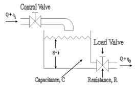
A simple liquid level system is shown in the below figure with steady flow rate, Q and steady state head, H.
|
Fig 11 Liquid Level System
Let Q = Steady state flow rate(before any change has occurred)
qi = Small deviation of inflow rate from its steady-state value
qo = Small deviation of outflow rate from its steady-state value
H = Steady state head (before any change has occurred)
h = Small deviation of head from its steady state value
Let the system be considered linear. The differential equation governing the system is obtained by equating the change in flow rate to the amount stored in the tank. In a small time interval dt, let the change in flow rate be (qi - qo) and the change in height be dh.
Now
, Change In storage = Change in flow rate
qo = h/R
|
The above equation is the differential equation governing the system.The term RC is the time constant of the system .On the Laplace's transform of above equation we get,
|
The above equation is the required transfer function of the Hydraulic system.
Key takeaway
Hydraulic fluid acts as a lubricant and coolant. Comparatively small sized hydraulic actuators can develop are forces or torques. Hydraulic actuators can be operated under continuous, intermittent, reversing, and called conditions without damage. Hydraulic actuators have a higher speed of response. They offer fast starts, stops and speed reversals. With availability of both linear and rotary actuators, the design has become more flexible.
Analogy Between Electrical and Mechanical System: -
Force -voltage | Force -current | Mechanical Translatory | Mechanical Rotational |
1.Voltage (v) | current | Force (f) | Torque (T) |
2.Charge(q) | Flux (ø) | Displacement(x) | Angular Displacement(ø) |
3.current. | voltage | Velocity v(t) | Angular velocity(w) |
4.Inductance(l) | Capacitance(c) | Mass (m) | Moment of inertia (J) |
5. Resistance(R) | Conductance G= (1/R) | Damping coefficient (B) | Damping Coefficient (B) |
6.Reciprocal of capacitance(1/c) | Inverse of Inductance (1/L) | Stiffness (K) | Stiffness(K) |
Advantages of Block diagram reduction technique:
- Very simple to Construct the Block diagram of complicated electrical & mechanical systems.
- The function of individual element can be visualized form block diagram
- Individual as well as overall performance of the system can be studied by the figure shown in Block diag.
- Overall CLTF can be easily calculated by Block diagram reduction rules.
Disadvantages of Block diagram reduction technique:
It does not include any information above physical construct of system (completely mathematical approach). Source of energy is generally not shown in the block diagram so diff. block diagram can be drawn for the same function.
CLTf: -ve feedback C(s)/R(s)= G(s)/1+G(s)H(s) CLTF:-+vefeedback C(S)/R(S) = G(S)/1-G(s)H(S)
|
Rules of Block diagram Algebra:
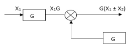
Block in cascade
|

 Moving summing point after a block
|

 Moving summing point ahead of block
|


 Moving take off point after a block
|
Moving take off point ahead a block
|
Eliminating a feedback Loop
|


 Practice Problems
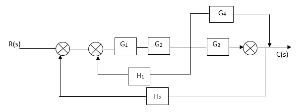
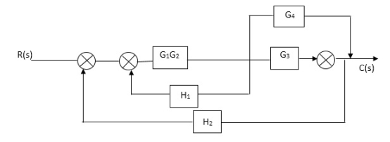
Q1. Reduce given B.D to canonical (simple form) and hence obtain the equivalent Tf = c(s)/ R(S)?


|
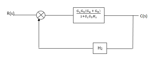
Sol:-
|


 C(S)/R(S) = (G1G2) (G3+G4)/1+G1G2H1)/1-G1,G2(G3+G4) H2/1+G1G2H1
= G1G2(G3+G4)/1+G1G2H1-G1G2H2(G3+G4)
=G1G2(G3+G4)/1+(H1-H2)(G1G2) (G3+G4)
C(s)/R(S) = G1G2(G3+G4)/1+(H1-H2(G3+G4)) G1 G2
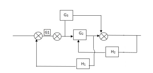
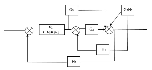
Q2) Reduce the Block diagram
|
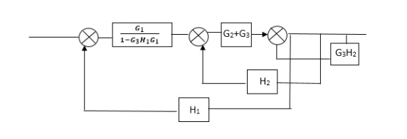
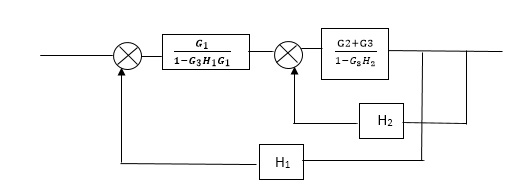
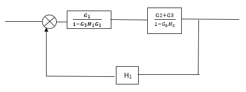
Sol
|


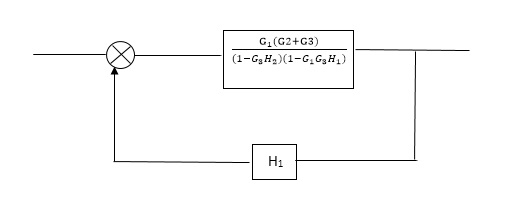
 C(s)/R(s)= G1(G3+G2)/(1-G1G3X1) (1-G2X2) H1
= G(G3+G2)/(1-G3G1H1) (1-G2H2) + G1H1(G3+G2)
= G1(G3+G2)/1-G3G1H1-G2H2+G1H1(G3+G2H1
=G1(G3+G2)/1-G3H2+G1G2H1(1+G3H2)
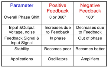
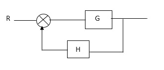
There are two types of feedbacks
i) Positive Feedback
|
Fig 12 Closed Loop control system
In positive feedback systems the feedback signal is added to the input signal. The positive feedback is used only in oscillators. The transfer function is given as
C(s)/ R(S) = G(s)/ 1-G(S) H(S) |
ii) Negative Feedback
In negative feedback the error signal is inverted at the input signal. The discussion in this unit is based on this negative feedback system only. The transfer function is given by
C(s)/ R(S) = G(s)/ 1+G(S) H(S) |
Key takeaway
|
Block Diagram
|
SFG
|
Practice Problem
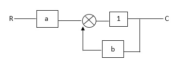
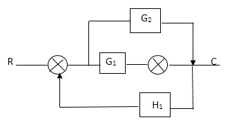
Q: For given block diagram draw the SFG?
|
|
|
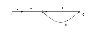
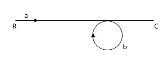
Ra+cb =c
c/R= a/1-b
RULES: -
1) The signal travels along a branch in the direction of an arrow.
2) The input signal is multiplied by the transmittance to obtain the o/p.
3) I/p signal at a node is sum of all the signals entering at that node.
4) A node transmits signal at all branches leaving that node.
|
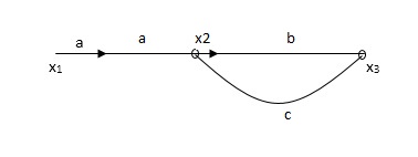
Soln:-
X1- I/p node X2-Intenmediale node X3- o/p node ab- forward path (p) bc- 1 loop (L) At node XQ: X2 = x1a + x3c [Add i/p signals at node] At node x3: x2b =x3 (x1a+x3c) b = x3 X1ab = x3 (1-bc) X1 = x3 (1-bc)/ab Ab/(1-bc) = x3/x1 T= p/1-L
|
|
X1:- I/p node x2, x3,x4,x5,Qnlexmedili node X0:- o/p node abdeg:- forward path bc, ef :- Loop [isolated] x2 = ax1+c x3 x3= bx2 x4 = d x3+f x5 x5 = e x4 x6= g x5 x6 = g(e x4) = ge [dx3+ e f x5] xb = ge [d (bx2) + f (e x4)] xb = ge [ db (ax1+cx3) + fe (dx3+ fx5)] xb = ge [db (ax1+cb (ax1+x3) +fe[cdbx2]+ f( e [db (ax1+ cx3) x2 = ax1 + cb (x2) x4 = d bx2 + f exq x2 = ax1 + cbx2 = db (d4) + fe/1-cb x2 = ax1/(1-cb) xy = db x2 + f x6/g xy = db [ax1]/1-cb + f xb/g x5 = c db ( ax1)/1-cb + efxb/g xb = gx5 = gedb (ax1)/1-cb + g efxb/g Xb = gx5 gedb (ax1)/1-cb + g efxb/g (1- gef/g) xb = gedb ax1/1-ab Xb/x1 = gedb a/ (1- ef – bc + beef Xb/x1 = p/ 1- (L1+L2) + L1 L2 for isolated loops
|
MASON’S GAIN FORMULA
The overall transmittance Coverall gain can be determined by Masks formula.
Explanation
Pk forward path transmittance of k+n path from a specified i/p node to n o/p nods
While calculating ipnode to n o/p nods.
While calculating ip no node should be encountered (used) more than ones.
 it is the graphics determined which involves of transmittances and multiple increases b/w non touching loops.
 = 1- [sum of all individual loop transmitting]
+[ sum of loop transmittance product of all possible non- touching loops]
-[sum of loop transmittance of all possible triples of non- touching loops]
 path factor associated with concered path & involves all a in the graphic which are isolated from forward path under consideration.
The path factor  for kthis equal to graph determinant of SFG which effect after erasing the kth path from the graph
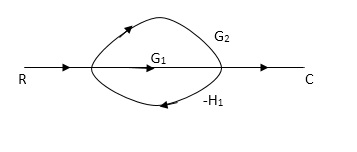
Q. Draw SFG for given block diagram?
|
Sol:
P1= G1 p2 =G2 Delta1 =1 L1= -G1 H1
= 1+G1H1 T= G1+G2/1+G1H1 |
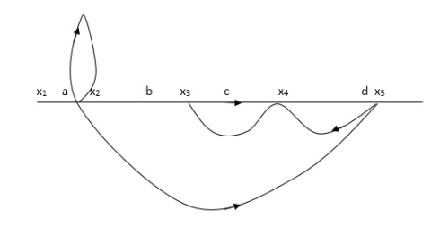
Q:- Determine overall gain x5 and x1 Draw SFG
X2 = ax1+ f x2 X3= bx2 +exy X4 = cx3+hx5 X5 =dx4 + gx2
P1 = abcd p2 = ag L1 = f L2 = ce, L3= dh
= 1-[f+ le = dh] + [fce +fdh] T= abcd+ ag (1-ce)/1-[ftce + dh ] + (fce + fdh) |
Key takeaway
i) The function of individual element can be visualized from block diagram
ii) The signal travels along a branch in the direction of an arrow.
iii) The input signal is multiplied by the transmittance to obtain the o/p
References:
1. “Control System Engineering”, Norman S. Nise,John willey and Sons, 6th Edition, 2015.
2. “Control System Engineering”,I.J. Nagrath and M. Gopal,New age International publication, 5th Edition, 2014.
3. “Modern Control Engineering”, Katsuhiko Ogata,Prentice Hall of India Pvt
Ltd, 5th edition.
4. “Automatic Control System”, Benjamin C. Kuo, Prentice Hall of India Pvt Ltd, Wiley publication, 9th edition


