UNIT - 2
Time Response
Transient Analysis of First Order System:
CLTF c(s)/R(s) = 1/1+TS CE: HTS = 0 S= -1/T C(s) = R(s) [G(S)/1+G(s)] C(s) = R(s)/1+TS So, Calculating value of c(s), c(t) for different input
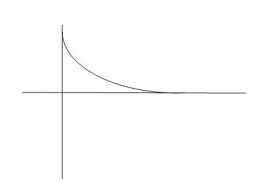
R(t) = u(t) R(s) = 1/s C(s) = 1/s(1+ST) 1/s(1+ST) = A/s + o/1+TS 1/s(1+ST) = A/S + 0/1+TS 1= A(1+ST) + BS AT +B =0 A = 1 B= -T C(s) = 1/s + (-T)/1+TS = 1+ (-T)/1-(-T)s = 1-I/n/1+ass+1/T =e-t/s C(t) = [ 1-e-t/T] |
|
|
|
|
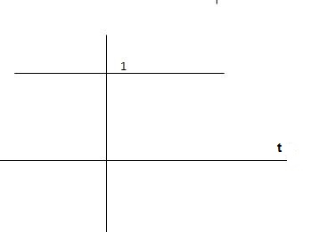
Fig 1 Output response for Unit Step input
Ramp:
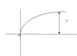
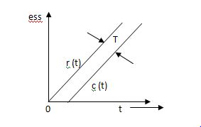
R(t) = t R(s) = 1/s2 C(s) = R(s) [G(s)/1+G(s)] C(s) = 1/s2 1/(1+TS) + c 1/s2 (1+TS) = A/(s) + B/s2 + c(1+TS) 1 = A (s+s2. T) + B(1+TS) +cs2 TA +c = 0 A+TB =0 B =1 A = -T C = T2 C(s) = -T/s + 1/s2 +T2/1+ST =(-T) u(t) + t(u) + T e-t/T u(t) = [ -T + t +Te-t/T u(t) = [ -T+ t+Te-t/T] u(t) C(s) = t- T+ Te-t/T ess =
= =
ess = The less the value of T the less in the errors.
|
Fig 2 Output response for ramp input
Key takeaway
- From both the Cases input unit step, ramp Unit step
|
- In both the vases (values of T) must be as small as possible (so, that e-t/T) must be as small as possible which gives us
|
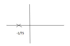
Fig 3 Location of poles
G(s) = 1/Ts
aTf = 1/1+TS
1st order system
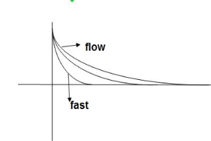
Poles must be situated as far as possible from origin i.e. deeper and deeper into the left half of s-place. Thus, we get less errors.
Transient Analysis of Second Order System:
CLTFC(s)/R(s) = k/k+s(1+Ts) = k/s2+ s/T +k/T Comparing above equation with standard 2nd order eqn
|
CEs2+2 S= -2 =2 S= S= - S= - S= - Standard eqn:- T(s) = wn2/s2+2 Our eqn T(s) = K/T/s2+1/T s+ K/T Wn2 = k/T 2 2
|
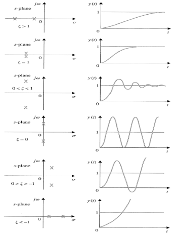
Graphically showing the position of loops s1,s2 for offered of
As the characteristic Equn (location of poles ) is dependent only on (wn constant for a given system.
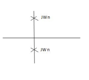
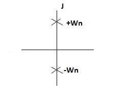
S1 = - S2= - CASE 1: ( S1=jwn,S2, = -jwn |
|
Fig 4 Location of poles for  =0
=0
Undamped
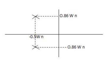
CASE 2:(0< S1= -wn + jwn =-wn/2 +jwn(0.26) S2 = -wn/2 – jwn (0.86)
|
Fig 5 Location of poles for  <1
<1
CASE:3 ( S1= S2 = -
|
Fig 6 Location of poles for  =1
=1
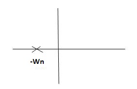
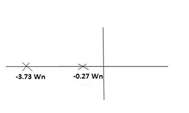
CASE 4:- ( S1 = -2wn +jwn =-2wn – jwn (1.73) S1 = -3.73wn S2 = -2wn –jwn = -2wn + jwn (1.73) = -0.27
|
Fig 7 Location of poles for  >1
>1
Overdamped
All practical systems are 2 order to, if R(e) =  (t) R(s) = 1 :. CLTF = 2nd order st eqn and hence already the system is possible.
CLTF = e(s)/ R(s) = wn2/s2+2 wns+wn2
Now calculating c(s) , c(t) for different values of input
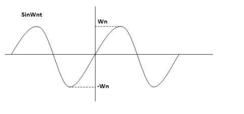
R(t) = R(s) = 1 C(s) = R(s) wn2/s2+2 C(s) = wn2/s2 +2 Under this i/p (R(t) = CONDITION 1: ( C(s) =wn2/s2 +wn2 os2 +wn2 =0 S=+-jwn C(t) = wn sinwnt
Sinwnt
|
Fig 8 Undamped oscillations
As there in no damping i.e. oscillations at t= 0 are some at t  so, called UNDAMPED
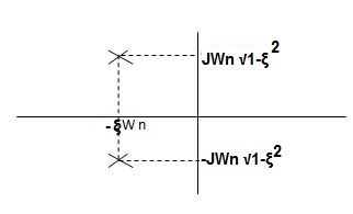
CONDITION 2: 0<<1 c(s) = R(s) wn2/s22 R(s) =1 C(s) = wn2/s2+2 CE S2+2 S2, S1 = -
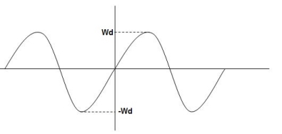
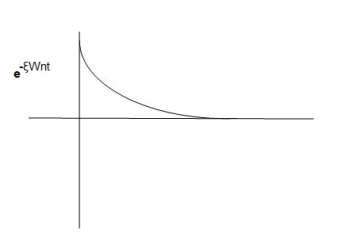
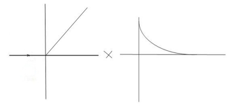
C(t) = e- Wd=wn
C(t)=e-
|
Fig 9 Underdamped oscillations
The oscillations are present but at t- infinity the Oscillations are 0 so, it is UNDERDAMPED
CONDITION 3 : C(s) = R(s) wn2/s2+2 C(s)=wn2/S2 +2wns+wn2 =wn2/(s +wn)2 CE S= -Wn Diagram C(t)= C(t)= |
|
|
Fig 10 Critically damped oscillations
No damping obtained at  so is called CRITICALLY DAMPED.
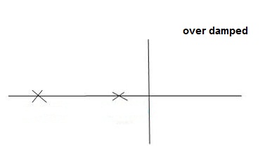
CONDITIONS 4 :- C(s) = wn2/s22 S1,s2 =
|
Fig 11 location of poles for over damped oscillations
- UNIT Step Input:-
R(s) = 1/s C(s)/R(s) = wn2/s2+2 C(s) = R(s) wn2 /s2 +2 C(s) = R(s) wn2/s2+2 C(s) = R(s) wn2/s2+2 C(s) = wn2s(s2+2 C(t) = 1- e Wd = wn Ø= Where Wd = Damping frequency of oscillations Wn = natural frequency of oscillations
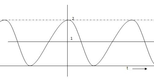
T= Time constant Condition 1 C(s) = wn2 /s(s2+wn2) C(t) = 1- e° sin wdt +ø C(t)= 1- sin( wn +90) C(t) = 1+cos wnt Constant |
|
|
|
Fig 12 C(t) = 1+cos wnt
Condition 2:- 0< C(s) = C(s) =1/s – s+ =1/s – s+ Wd = wn Taking Laplace inverse of above equation L --1 s+ L-1 s+ C(t) = 1-e- = 1-e C(t) = 1-e Ø = |
|
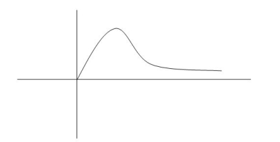
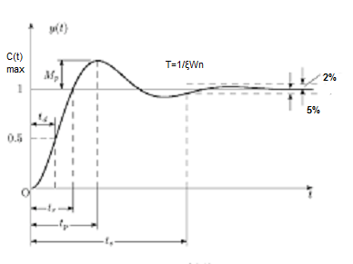
Fig 13 Transient Response of second order system
Specifications:
- Rise Time (tp):- The time taken by the output to reach the already status value for the first time is known as Rise time.
C(t) = 1-e- Sin (wd +ø) = 0 Wdt +ø = n tr =n for first time so ,n=1.
|
- Peak Time (tp)
The peak value attained by the output is called peak time. The time required by the output to reach this value is lp.
d(cct) /dt = 0 (maxima) d(t)/dt = peak value tp = n tp = |
3) Peak Overshoot Value:
Maximum deviation of output from steady state value is called peak overshoot value (Mp).
(ltp) = 1 = Mp ( ( Mp = e-∏ξ / √1 –ξ2 Condition 3 ξ = 1 C( S ) = R( S ) Wn2 / S2 + 2ξWnS + Wn2 C( S ) = Wn2 / S(S2 + 2WnS + Wn2) [ R(S) = 1/S ] C( S ) = Wn2 / S( S2 + Wn2 ) C( t ) = 1 – e-Wnt + tWne-Wnt The response is critically damped. |
(4). Settling Time (ts) :
ts = 3 / ξWn ( 5% ) ts = 4 / ξWn ( 2% ) |
Key takeaway
tp = 3. Peak Overshoot Value Mp% = e-∏ξ / √1 –ξ2 4. Settling Time ts = 3 / ξWn ( 5% ) ts = 4 / ξWn ( 2% ) |
Examples
Soln : Finding closed loop transfer function, C( S ) / R( S ) = G( S ) / 1 + G( S ) + H( S ) As it is unity feedback so, H(S) = 1 C(S)/R(S) = G(S)/1 + G(S) = 20/S2 + 5S + 4/1 + 20/S2 + 5S + 4 C(S)/R(S) = 20/S2 + 5S + 24 Standard equation for second order system, S2 + 2ξWnS + Wn2 = 0 We have, S2 + 5S + 24 = 0 Wn2 = 24 Wn = 4.89 rad/sec 2ξWn = 5 (a). ξ = 5/2 x 4.89 = 0.511 (b). Mp% = e-∏ξ / √1 –ξ2 x 100 = e-∏ x 0.511 / √1 – (0.511)2 x 100 Mp% = 15.4%
(c). tr = ∏ - φ / Wd φ = tan-1√1 – ξ2 / ξ φ= tan-1√1 – (0.511)2 / (0.511) φ = 1.03 rad. tr = ∏ - 1.03/Wd Wd = Wn√1 – ξ2 = 4.89 √1 – (0.511)2 Wd = 4.20 rad/sec tr = ∏ - 1.03/4.20 tr = 502.34 msec (d). tp = ∏/4.20 = 747.9 msec |
Q.2. A second order system has Wn = 5 rad/sec and is ξ = 0.7 subjected to unit step input. Find (i) closed loop transfer function. (ii) Peak time (iii) Rise time (iv) Settling time (v) Peak overshoot.
Soln: The closed loop transfer function is
C(S)/R(S) = Wn2 / S2 + 2ξWnS + Wn2 = (5)2 / S2 + 2 x 0.7 x S + (5)2 C(S)/R(S) = 25 / S2 + 7s + 25
(ii). tp = ∏ / Wd Wd = Wn√1 - ξ2 = 5√1 – (0.7)2 = 3.571 sec
(iii). tr = ∏ - φ/Wd φ= tan-1√1 – ξ2 / ξ = 0.795 rad tr = ∏ - 0.795 / 3.571 tr = 0.657 sec
(iv). For 2% settling time ts = 4 / ξWn = 4 / 0.7 x 5 ts = 1.143 sec
(v). Mp = e-∏ξ / √1 –ξ2 x 100 Mp = 4.59% |
Q.3. The open loop transfer function of a unity feedback control system is given by G(S) = K/S(1 + ST)
Calculate the value by which k should be multiplied so that damping ratio is increased from 0.2 to 0.4?
Soln:
C(S)/R(S) = G(S) / 1 + G(S)H(S) H(S) = 1 C(S)/R(S) = K/S(1 + ST) / 1 + K/S(1 + ST) C(S)/R(S) = K/S(1 + ST) + K C(S)/R(S) = K/T / S2 + S/T + K/T For second order system, S2 + 2ξWnS + Wn2 2ξWn = 1/T ξ = 1/2WnT Wn2 = K/T Wn =√K/T ξ = 1 / 2√K/T T ξ = 1 / 2 √KT forξ1 = 0.2, for ξ2 = 0.4 ξ1 = 1 / 2 √K1T ξ2 = 1 / 2 √K2T ξ1/ ξ2 = √K2/K1 K2/K1 = (0.2/0.4)2 K2/K1 = 1 / 4 K1 = 4K2 |
Q.4. Consider the transfer function C(S)/R(S) = Wn2 / S2 + 2ξWnS + Wn2
Find ξ, Wn so that the system responds to a step input with 5% overshoot and settling time of 4 sec?
Soln:
Mp = 5% = 0.05 Mp = e-∏ξ / √1 –ξ2 0.05 = e-∏ξ / √1 –ξ2 Cn 0.05 = - ∏ξ / √1 –ξ2 -2.99 = - ∏ξ / √1 –ξ2 8.97(1 – ξ2) = ξ2∏2 0.91 – 0.91 ξ2 = ξ2 0.91 = 1.91 ξ2 ξ2 = 0.69
(ii). ts = 4/ ξWn 4 = 4/ ξWn Wn = 1/ ξ = 1/ 0.69 Wn = 1.45 rad/sec |
So, for difficult input, ess will be different Input still be
R(t) = u(t) R(s) = 1/s ess = = ess=
(Position error coefficient)
R(t) = t R(s) = 1/s2 ess= = = = ess = ess =
(3)Parabolic R(t) = t2 R(s) =1/s3 ess = = = Ess = Ka =
I/p error coefficient (1)Unit step ess= 1/1+kv kv =
(2)Ramp ess= 1/kv kv =
(3)Parabolic ess = 1/ka ka =
|
finding errors in type 0,1,2 system
G(s) = 1/(s+a) (s+b)
Kp = = Kp= 1/ab ess=1/1+np = 1/1+(1/ab) o/p not locking the input (b) kv:- Kv =
= = kv = 0 ess = 1/kv = o/p not locating the input (3)ka:- ka = = Ka =0 ess = 1/ka = o/p not locking the input (2)Type –I :- G(s) = 1/s(s+a) (s+b)
Kp =
=
Kp = 1/0 = ess = 1/1+kp = 0 o/p is tracking the input (b)kv:- Kv =
= =1/ab Kv = 1/ab ess =1/ka = ab o/p is not tracking the input 3)ka : Ka= = = Ka= 0 ess = 1/ka = O/p is not tracking the input. Type 2 :- G(s) = 1+/(s2(s+a) (s+b) a) Kp:- Kp = = Kp = ess = 1/1+kp = 0 o/p tracking the i/p b) kv:- Kv =
= kv = ess =1/ o/p tracking the o/p (b) ka:- Ka= = ka = 1/ab ess = 1/(yab) ≠0 o/p not locking the i/p |
Key takeaway:
|
Unit step ≠0 0 0 |
Ramp |
Parabolic |
Static error constants can be used to specify the steady state error characteristics of control systems. Just as damping ratio, settling time, peak time and % overshoot is used as specifications for a control systems transient response. So, the position constant Kp velocity constant Kv and acceleration constant Ka can be used as specifications for a control system steady state error.
A stable system always gives bounded output for bounded input and the system is known as BIBO stable
A linear time invariant (LTI) system is stable if,
The system is BIBO stable
In absence of the input the output tends towards zero
For system
|
Fig 14 Control system with G(s) = 1/s2
For R(s) = 1 C(S) = R (t) =
T Bounded Unbounded Fig 15 Input R(t) Fig 16 Input and output for
|
So, system unstable.
[R(s) = 1]
C(t) = e-10t C(t) |
Fig 17 BIBO stable figure
- Real and negative G(s)=

C(t) -a
|
Fig 18 Output for G(s)= 
Stable
0 t Unstable:- Unbounded Output Fig 19 Input and Output for G(s) =
|
(C)Poles at origin
G(s)=
k
|
Marginally stable
Fig 20 Input and output for G(s)=
4) Complex poles on left half of S-plane
S1,S2= -α ± iw
C(t) = k e- αt Cos wt | |
|
|
Fig 21 Pole location and output for C(t) = k e- αt Cos wt
At t - ∞ C(t) – 0 so, system stable
5) Complex poles on right half of S-plane
S1,S2 = α ± iw. C(t) = k eαt COS wt.
So, unstable. |
6) Poles on iw axis:
S1,S2 = ± iw. C(t) = k COS wt.
0
|
Fig 22 Output response of C(t) = k COS wt.
The system is marginally stable than sustained oscillations.
Key takeaway
Consider a system with characteristic equation
aoSm + a1 Sm-1 ……………..am=0.
- All the coefficients of above equation should have same sign.
- There should be no missing term.
The above two condition are necessary but not sufficient condition for stability
It states that the system is stable if and only if all the elements is the first column have the same algebraic sign. If all elements are not of the same sign, then the number of sign changes of elements in first column equals the number of roots of the characteristic equation in the right half of S-plane.
Consider the following characteristic equation:
a0 Sn + a1 Sn-1 ………….an = 0 where a0,a1,,,,,,,,,,,,,,,,,,,,an have same sign and are non-zero.
Step1 Arrange coefficients in rows Row1 ao a2 a4 Row2 a1 a3 a5 Step2 Find third row from above two rows Row1 a0 a2 a4 Row2 a1 a3 a5 Row3 a1 a3 a5
a1 = a3 = |
Continue the same procedure to find new rows.
Q1) for the given polynomials below determine the stability of the system S4+2S3+3S2+4S+5=0 1) Arranging Coefficient in Rows.
For row S2 first term S2 = For row S2 Second term S2 = For row S1: S1 = For row S0 S0 = As there are two sign change in the first column, So there are two roots or right half of S-plane making system unstable.
|
Q2. Using Routh criterion determine the stability of the system with characteristic equation S4+8S3+18S2+16S+S = 0
Sol:- Arrange in rows.
| 1 | 18 | 5 |
S3 | 8 | 16 | 0 |
S2 | 16 | 5 |
|
S1 | 13.5 |
|
|
S0 | 5 |
|
|
For row S2 first element
S1 =  = 16
= 16
Second terms =  = 5
= 5
For S1
First element =  = 13.5
For S0
First element =  = 5
= 5
As there is no sign change for first column so all roots are is left half of S-plane and hence system is stable.
Special Cases of Routh Hurwitz Criterions
- When first element of any row is zero.
In this case the zero is replaced by a very small positive number E and rest of the array is evaluated.
Eg.(1) Consider the following equation
S3+S+2 = 0
| 1 | 1 |
S2 | 0 | 2 |
S1 |
|
|
Replacing 0 by E

S3 | 1 | 1 |
S2 | E | 2 |
S1 |
| 0 |
S0 | 2 |
|
Now when E  0, values in column 1 becomes
| 1 | 1 |
| E | 2 |
|
| 0 |
S0 | 2 |
|
Two sign changes hence two roots on right side of S-plans
II) When any one row is having all its terms zero.
When array one row of Routh Hurwitz table is zero, it shown that the X is attests one pair of roots which lies radially opposite to each other in this case the array can be completed by auxiliary polynomial. It is the polynomial row first above row zero.
Consider following example
S3 + 5S2 + 6S + 30
| 1 | 6 |
| 5 |
|
| 0 | 0 |
S0 |
|
|
For forming auxiliary equation, selecting row first above row hang all terms zero.
A(s) = 5S2 e 30
 = 10s e0.
Again forming Routh array
| 1 | 6 |
S2 | 5 | 30 |
S1 | 10 |
|
S0 | 30 |
|
No sign change in column one the roots of Auxiliary equation A(s)=5s2+ 30-0
5s2+30 = 0
S2 α 6= 0
S = ± j 
Both lie on imaginary axis so system is marginally stable.
Q3. Determine the stability of the system represent by following characteristic equations using Routh criterion
1) S4 + 3s3 + 8s2 + 4s +3 = 0
2) S4 + 9s3 + 4S2 – 36s -32 = 0
1) S4+3s3+8s2+4s+3=0
S4 | 1 | 8 | 3 |
S3 | 3 | 4 | 0 |
S2 | 6.66 | 3 |
|
S1 | 2.650 | 0 |
|
S0 | 3 |
|
|
No sign change in first column to no rows on right half of S-plane system stable.
S4+9S3+4S2-36S-32 = 0
S4 | 1 | 4 | -32 |
| 9 |
| 0 |
| 8 | -32 |
|
S1 | 0 | 0 |
|
S0 |
|
|
|
Special case II of Routh Hurwitz criterion forming auxiliary equation
A1 (s) = 8S2 – 32 = 0
 = 16S – 0 =0
S4 | 1 | 4 | -32 |
S3 | 9 | -36 | 0 |
S2 | 8 | -32 |
|
| 16 | 0 |
|
S0 | -32 |
|
|
One sign change so, one root lies on right half S-plane hence system is unstable.
Q4. For using feedback open loop transfer function G(s) = 
find range of k for stability
Soln:- Findlay characteristics equation .
CE = 1+G (s) H(s) = 0 H(s) =1 using feedback CE = 1+ G(s) 1+ S(S+1)(S+3)(S+4)+k = 0 (S2+5)(S2+7Sα12)αK = 0 S4α7S3α1252+S3α7S2α125αK = 0 S4+8S3α19S2+125+k = 0 By Routh Hurwitz Criterion
|
S4 | 1 | 19 | K |
S3 | 8 | 12 | 0 |
S2 | 17.5 | K |
|
S1 |
| 0 |
|
S0 | k |
|
|
For system to be stable the range of K is 0< K <  .
.
| 1 | 12 | K |
S3 | 4 | 36 |
|
S2 | 3 | K |
|
S1 |
|
|
|
S0 | K |
|
|
Q5. The characteristic equation for certain feedback control system is given. Find range of K for system to be stable.
Soln
S4+4S3α12S2+36SαK = 0
For stability K>0
 > 0
> 0
K < 27
Range of K will be 0 < K < 27
Relative Stability Criterion:
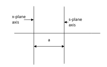
Routh stability criterion deals about absolute stability of any closed loop system. For relative stability we need to shift the S-plane and the apply the Routh criterion.
|
Fig 23 Location of Pole for relative stability
The above fig 10 shows the characteristic equation is modified by shifting the origin of S-plane to S1= - .
.
S = Z-S1
After substituting new valve of S =(Z-S1) applying Routh stability criterion, the number of sign changes in first column is the number of roots on right half of S-plane
Q6. Check if all roots of equation
S3+6S2+25S+38 = 0, have real poll more negative than -1.
Soln:-
S3 | 1 | 25 |
|
S2 | 6 | 38 |
|
S1 | 18.67 |
|
|
S0 | 38 |
|
|

No sign change in first column, hence all roots are in left half of S-plane.
Replacing S = Z-1. In above equation
(Z-1)3+6(Z-1)2+25(Z-1)+38 = 0
Z3+ Z23+16Z+18=0
Z3 | 1 | 16 |
Z2 | 3 | 18 |
Z1 | 10 |
|
Z0 | 18 |
|

No sign change in first column roots lie on left half of Z-plane hence all roots of original equation in S-domain lie to left half 0f S = -1
Key takeaway
Special Cases of Routh Hurwitz Criterions
When first element of any row is zero
In this case the zero is replaced by a very small positive number E and rest of the array is evaluated.
When any one row is having all its terms zero.
When array one row of Routh Hurwitz table is zero, it shown that the X is attests one pair of roots which lies radially opposite to each other in this case the array can be completed by auxiliary polynomial. It is the polynomial row first above row zero.
References:
1. “Control System Engineering”, Norman S. Nise,John willey and Sons, 6th Edition, 2015.
2. “Control System Engineering”,I.J. Nagrath and M. Gopal,New age International publication, 5th Edition, 2014.
3. “Modern Control Engineering”, Katsuhiko Ogata,Prentice Hall of India Pvt
Ltd, 5th edition.
4. “Automatic Control System”, Benjamin C. Kuo, Prentice Hall of India Pvt Ltd, Wiley publication, 9th edition
