UNIT 6
Real Time Operating Systems
What is a Real-Time Operating System (RTOS)?
Real-time operating system (RTOS) is an operating system intended to serve real time application that process data as it comes in, mostly without buffer delay. The full form of RTOS is Real time operating system.
In a RTOS, Processing time requirement are calculated in tenths of seconds increments of time. It is time-bound system that can be defined as fixed time constraints. In this type of system, processing must be done inside the specified constraints. Otherwise, the system will fail.
Why use an RTOS?
Here are important reasons for using RTOS:
Components of RTOS
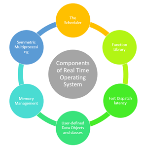
Fig 1 - Components of Real Time Operating System
Here, are important Component of RTOS
The Scheduler: This component of RTOS tells that in which order, the tasks can be executed which is generally based on the priority.
Symmetric Multiprocessing (SMP): It is a number of multiple different tasks that can be handled by the RTOS so that parallel processing can be done.
Function Library: It is an important element of RTOS that acts as an interface that helps you to connect kernel and application code. This application allows you to send the requests to the Kernel using a function library so that the application can give the desired results.
Memory Management: this element is needed in the system to allocate memory to every program, which is the most important element of the RTOS.
Fast dispatch latency: It is an interval between the termination of the task that can be identified by the OS and the actual time taken by the thread, which is in the ready queue, that has started processing.
User-defined data objects and classes: RTOS system makes use of programming languages like C or C++, which should be organized according to their operation.
Types of RTOS -
Three types of RTOS systems are:
Hard Real Time :
In Hard RTOS, the deadline is handled very strictly which means that given task must start executing on specified scheduled time, and must be completed within the assigned time duration.
Example: Medical critical care system, Aircraft systems, etc.
Firm Real time:
These type of RTOS also need to follow the deadlines. However, missing a deadline may not have big impact but could cause undesired affects, like a huge reduction in quality of a product.
Example: Various types of Multimedia applications.
Soft Real Time:
Soft Real time RTOS, accepts some delays by the Operating system. In this type of RTOS, there is a deadline assigned for a specific job, but a delay for a small amount of time is acceptable. So, deadlines are handled softly by this type of RTOS.
Example: Online Transaction system and Livestock price quotation System.
Terms used in RTOS
Here, are essential terms used in RTOS:
Features of RTOS-
Here are important features of RTOS:
Factors for selecting an RTOS-
Here, are essential factors that you need to consider for selecting RTOS:
Difference between in GPOS and RTOS
Here are important differences between GPOS and RTOS:
General-Purpose Operating System (GPOS) | Real-Time Operating System (RTOS) |
It used for desktop PC and laptop. | It is only applied to the embedded application. |
Process-based Scheduling. | Time-based scheduling used like round-robin scheduling. |
Interrupt latency is not considered as important as in RTOS. | Interrupt lag is minimal, which is measured in a few microseconds. |
No priority inversion mechanism is present in the system. | The priority inversion mechanism is current. So it can not modify by the system. |
Kernel's operation may or may not be preempted. | Kernel's operation can be preempted. |
Priority inversion remain unnoticed . | No predictability guarantees.
|
Applications of Real Time Operating System
Real-time systems are used in:
Disadvantages of RTOS
Here, are drawbacks/cons of using RTOS system:
Summary:
Key takeaway-
What is a Real-Time Operating System (RTOS)?
Real-time operating system (RTOS) is an operating system intended to serve real time application that process data as it comes in, mostly without buffer delay. The full form of RTOS is Real time operating system.
In a RTOS, Processing time requirement are calculated in tenths of seconds increments of time. It is time-bound system that can be defined as fixed time constraints. In this type of system, processing must be done inside the specified constraints. Otherwise, the system will fail.
Task States and Scheduling
Whether it's a system task or an application task, at any time each task exists in one of a small number of states, including ready, running, or blocked. As the real-time embedded system runs, each task moves from one state to another, according to the logic of a simple finite state machine (FSM). A typical FSM for task execution states, with brief descriptions of state transitions.
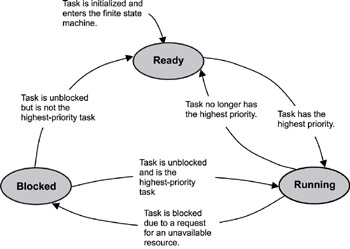
Figure 2: A typical finite state machine for task execution states.
Although kernels can define task-state groupings differently, generally three main states are used in most typical preemptive-scheduling kernels, including:
Note some commercial kernels, such as the VxWorks kernel, define other, more granular states, such as suspended, pended, and delayed. In this case, pended and delayed are actually sub-states of the blocked state. A pended task is waiting for a resource that it needs to be freed; a delayed task is waiting for a timing delay to end. The suspended state exists for debugging purposes. For more detailed information on the way a particular RTOS kernel implements its FSM for each task, refer to the kernel's user manual.
Regardless of how a kernel implements a task's FSM, it must maintain the current state of all tasks in a running system. As calls are made into the kernel by executing tasks, the kernel's scheduler first determines which tasks need to change states and then makes those changes.
In some cases, the kernel changes the states of some tasks, but no context switching occurs because the state of the highest priority task is unaffected. In other cases, however, these state changes result in a context switch because the former highest priority task either gets blocked or is no longer the highest priority task. When this process happens, the former running task is put into the blocked or ready state, and the new highest priority task starts to execute.
The following describe the ready, running, and blocked states in more detail. These descriptions are based on a single-processor system and a kernel using a priority-based preemptive scheduling algorithm.
When a task is first created and made ready to run, the kernel puts it into the ready state. In this state, the task actively competes with all other ready tasks for the processor's execution time. Tasks in the ready state cannot move directly to the blocked state. A task first needs to run so it can make a blocking call , which is a call to a function that cannot immediately run to completion, thus putting the task in the blocked state. Ready tasks, therefore, can only move to the running state. Because many tasks might be in the ready state, the kernel's scheduler uses the priority of each task to determine which task to move to the running state.
For a kernel that supports only one task per priority level, the scheduling algorithm is straightforward-the highest priority task that is ready runs next. In this implementation, the kernel limits the number of tasks in an application to the number of priority levels.
However, most kernels support more than one task per priority level, allowing many more tasks in an application. In this case, the scheduling algorithm is more complicated and involves maintaining a task-ready list . Some kernels maintain a separate task-ready list for each priority level; others have one combined list.
In a five-step scenario, how a kernel scheduler might use a task-ready list to move tasks from the ready state to the running state. This example assumes a single-processor system and a priority-based preemptive scheduling algorithm in which 255 is the lowest priority and 0 is the highest. Note that for simplicity this example does not show system tasks, such as the idle task.
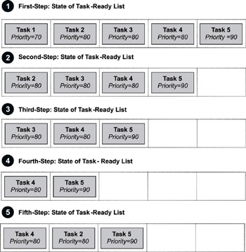
Figure 3: Five steps showing the way a task-ready list works.
In this example, tasks 1, 2, 3, 4, and 5 are ready to run, and the kernel queues them by priority in a task-ready list. Task 1 is the highest priority task (70); tasks 2, 3, and 4 are at the next-highest priority level (80); and task 5 is the lowest priority (90). The following steps explains how a kernel might use the task-ready list to move tasks to and from the ready state:
Although not illustrated here, if task 1 became unblocked at this point in the scenario, the kernel would move task 1 to the running state because its priority is higher than the currently running task (task 3). As with task 2 earlier, task 3 at this point would be moved to the ready state and inserted after task 2 (same priority of 80) and before task 5 (next priority of 90).
On a single-processor system, only one task can run at a time. In this case, when a task is moved to the running state, the processor loads its registers with this task's context. The processor can then execute the task's instructions and manipulate the associated stack.
A task can move back to the ready state while it is running. When a task moves from the running state to the ready state, it is preempted by a higher priority task. In this case, the preempted task is put in the appropriate, priority-based location in the task-ready list, and the higher priority task is moved from the ready state to the running state.
Unlike a ready task, a running task can move to the blocked state in any of the following ways:
The possibility of blocked states is extremely important in real-time systems because without blocked states, lower priority tasks could not run. If higher priority tasks are not designed to block, CPU starvation can result.
CPU starvation occurs when higher priority tasks use all of the CPU execution time and lower priority tasks do not get to run.
A task can only move to the blocked state by making a blocking call, requesting that some blocking condition be met. A blocked task remains blocked until the blocking condition is met. (It probably ought to be called the un blocking condition, but blocking is the terminology in common use among real-time programmers.) Examples of how blocking conditions are met include the following:
When a task becomes unblocked, the task might move from the blocked state to the ready state if it is not the highest priority task. The task is then put into the task-ready list at the appropriate priority-based location, as described earlier.
However, if the unblocked task is the highest priority task, the task moves directly to the running state (without going through the ready state) and preempts the currently running task. The preempted task is then moved to the ready state and put into the appropriate priority-based location in the task-ready list.
Introduction:
When two or more process cooperates with each other, their order of execution must be preserved otherwise there can be conflicts in their execution and inappropriate outputs can be produced.
A cooperative process is the one which can affect the execution of other process or can be affected by the execution of other process. Such processes need to be synchronized so that their order of execution can be guaranteed.
The procedure involved in preserving the appropriate order of execution of cooperative processes is known as Process Synchronization. There are various synchronization mechanisms that are used to synchronize the processes.
Race Condition:
A Race Condition typically occurs when two or more threads try to read, write and possibly make the decisions based on the memory that they are accessing concurrently.
Critical Section:
The regions of a program that try to access shared resources and may cause race conditions are called critical section. To avoid race condition among the processes, we need to assure that only one process at a time can execute within the critical section.
Process Communication in Operating System:
Processes that executing concurrently in the operating system may be either independent processes or cooperating processes. if a process cannot affect or be affected by the other processes executing in the system then the process is said to be independent. So any process that does not share any data with any other process is independent. A process is said to be cooperating if it can affect or be affected by the other processes executing in the system. So it is clear that, any process which shares its data with other processes is a cooperating process.
There are many reasons for providing an environment that allows process cooperation −
Cooperating processes need an inter-process communication (IPC) mechanism that will allow them to exchange data and information. Two basic models of inter-process communication are there: shared memory and message passing. A region of memory that is shared by cooperating processes is established, in shared-memory model.
Processes can then exchange their information by reading and writing data to the shared region. In message-passing model, communication takes place by means of messages exchanged between the cooperating processes. The two communications models are contrasted in Figure below. Both of the models which are mentioned, common in operating systems, and many systems implement both. Message passing is needful for exchanging smaller amounts of data, because no conflicts need be avoided. It is also easier to implement in a distributed system than shared memory. Once shared memory is initiated, all accesses are treated as routine memory accesses, and no assistance from the kernel is required. It suffers from cache coherency issues, which arise because shared data migrate among the several caches. Since the number of processing cores on systems increases, it is possible that we will see message passing as the preferred mechanism for IPC.
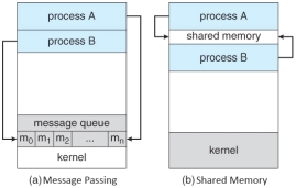
Figure 4: Communication Models
Concurrency in Operating System
Concurrency is the execution of the multiple instruction sequences at the same time. It happens in the operating system when there are several process threads running in parallel. The running process threads always communicate with each other through shared memory or message passing. Concurrency results in sharing of resources result in problems like deadlocks and resources starvation.
It helps in techniques like coordinating execution of processes, memory allocation and execution scheduling for maximizing throughput.
Principles of Concurrency :
Both interleaved and overlapped processes can be viewed as examples of concurrent processes, they both present the same problems.
The relative speed of execution cannot be predicted. It depends on the following:
Problems in Concurrency :
Sharing of global resources safely is difficult. If two processes both make use of a global variable and both perform read and write on that variable, then the order iin which various read and write are executed is critical.
It is difficult for the operating system to manage the allocation of resources optimally.
It is very difficult to locate a programming error because reports are usually not reproducible.
It may be inefficient for the operating system to simply lock the channel and prevents its use by other processes.
Advantages of Concurrency :
It enable to run multiple applications at the same time.
It enables that the resources that are unused by one application can be used for other applications.
Without concurrency, each application has to be run to completion before the next one can be run.
It enables the better performance by the operating system. When one application uses only the processor and another application uses only the disk drive then the time to run both applications concurrently to completion will be shorter than the time to run each application consecutively.
Drawbacks of Concurrency:
Issues of Concurrency:
Operations that are non-atomic but interruptible by multiple processes can cause problems.
A race condition occurs of the outcome depends on which of several processes gets to a point first.
Processes can block waiting for resources. A process could be blocked for long period of time waiting for input from a terminal. If the process is required to periodically update some data, this would be very undesirable.
It occurs when a process does not obtain service to progress.
It occurs when two processes are blocked and hence neither can proceed to execute.
Introduction to Deadlock-
Every process needs some resources to complete its execution. However, the resource is granted in a sequential order.
A Deadlock is a situation where each of the computer process waits for a resource which is being assigned to some another process. In this situation, none of the process gets executed since the resource it needs, is held by some other process which is also waiting for some other resource to be released.
Let us assume that there are three processes P1, P2 and P3. There are three different resources R1, R2 and R3. R1 is assigned to P1, R2 is assigned to P2 and R3 is assigned to P3.
After some time, P1 demands for R1 which is being used by P2. P1 halts its execution since it can't complete without R2. P2 also demands for R3 which is being used by P3. P2 also stops its execution because it can't continue without R3. P3 also demands for R1 which is being used by P1 therefore P3 also stops its execution.
In this scenario, a cycle is being formed among the three processes. None of the process is progressing and they are all waiting. The computer becomes unresponsive since all the processes got blocked.
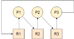
Fig 5 - Deadlock
Difference between Starvation and Deadlock
Sr. | Deadlock | Starvation |
1 | Deadlock is a situation where no process got blocked and no process proceeds | Starvation is a situation where the low priority process got blocked and the high priority processes proceed. |
2 | Deadlock is an infinite waiting. | Starvation is a long waiting but not infinite. |
3 | Every Deadlock is always a starvation. | Every starvation need not be deadlock. |
4 | The requested resource is blocked by the other process. | The requested resource is continuously be used by the higher priority processes. |
5 | Deadlock happens when Mutual exclusion, hold and wait, No preemption and circular wait occurs simultaneously. | It occurs due to the uncontrolled priority and resource management. |
Necessary conditions for Deadlocks-
A resource can only be shared in mutually exclusive manner. It implies, if two process cannot use the same resource at the same time.
2. Hold and Wait
A process waits for some resources while holding another resource at the same time.
3. No preemption
The process which once scheduled will be executed till the completion. No other process can be scheduled by the scheduler meanwhile.
4. Circular Wait
All the processes must be waiting for the resources in a cyclic manner so that the last process is waiting for the resource which is being held by the first process.
Key takeaway
Task States and Scheduling
Whether it's a system task or an application task, at any time each task exists in one of a small number of states, including ready, running, or blocked. As the real-time embedded system runs, each task moves from one state to another, according to the logic of a simple finite state machine (FSM). A typical FSM for task execution states, with brief descriptions of state transitions.
Semaphores are integer variables that are used to solve the critical section problem by using two atomic operations, wait and signal that are used for process synchronization.
The definitions of wait and signal are as follows −
The wait operation decrements the value of its argument S, if it is positive. If S is negative or zero, then no operation is performed.
wait(S)
{
while (S<=0);
S--;
}
The signal operation increments the value of its argument S.
signal(S)
{
S++;
}
Types of Semaphores-
There are two main types of semaphores i.e. counting semaphores and binary semaphores. Details about these are given as follows −
1) Counting Semaphores:
These are integer value semaphores and have an unrestricted value domain. These semaphores are used to coordinate the resource access, where the semaphore count is the number of available resources. If the resources are added, semaphore count automatically incremented and if the resources are removed, the count is decremented.
2) Binary Semaphores:
The binary semaphores are like counting semaphores but their value is restricted to 0 and 1. The wait operation only works when the semaphore is 1 and the signal operation succeeds when semaphore is 0. It is sometimes easier to implement binary semaphores than counting semaphores.
Advantages of Semaphores-
Some of the advantages of semaphores are as follows −
1) Semaphores allow only one process into the critical section. They follow the mutual exclusion principle strictly and are much more efficient than some other methods of synchronization.
2) There is no resource wastage because of busy waiting in semaphores as processor time is not wasted unnecessarily to check if a condition is fulfilled to allow a process to access the critical section.
3) Semaphores are implemented in the machine independent code of the microkernel. So they are machine independent.
Disadvantages of Semaphores
Some of the disadvantages of semaphores are as follows −
1) Semaphores are complicated so the wait and signal operations must be implemented in the correct order to prevent deadlocks.
2) Semaphores are impractical for last scale use as their use leads to loss of modularity. This happens because the wait and signal operations prevent the creation of a structured layout for the system.
3) Semaphores may lead to a priority inversion where low priority processes may access the critical section first and high priority processes later.
Key takeaway-
Semaphores are integer variables that are used to solve the critical section problem by using two atomic operations, wait and signal that are used for process synchronization.
The definitions of wait and signal are as follows −
The wait operation decrements the value of its argument S, if it is positive. If S is negative or zero, then no operation is performed.
wait(S)
{
while (S<=0);
S--;
}
2. Signal-
The signal operation increments the value of its argument S.
signal(S)
{
S++;
}
Process Queues
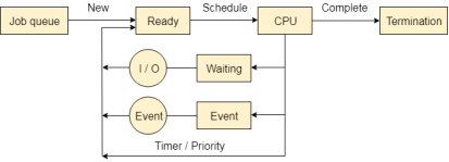
The Operating system manages various types of queues for each of the process states. The PCB related to the process is also stored in the queue of the same state. If the Process is moved from one state to another state then its PCB is also unlinked from the corresponding queue and added to the other state queue in which the transition is made.
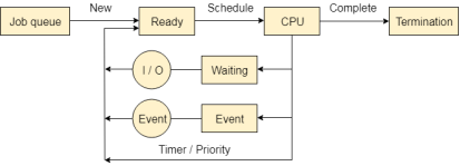
Fig 6 – Process queues
There are the following queues maintained by the Operating system.
1. Job Queue:
In starting, all the processes get stored in the job queue. It is maintained in the secondary memory. The long term scheduler (Job scheduler) picks some of the jobs and put them in the primary memory.
2. Ready Queue:
Ready queue is maintained in primary memory. The short term scheduler picks the job from the ready queue and dispatch to the CPU for the execution.
3. Waiting Queue:
When the process needs some IO operation in order to complete its execution, OS changes the state of the process from running to waiting. The context (PCB) associated with the process gets stored on the waiting queue which will be used by the Processor when the process finishes the IO.
Various Times related to the Process:
1. Arrival Time:
The time at which the process enters into the ready queue is called the arrival time.
2. Burst Time:
The total amount of time required by the CPU to execute the whole process is called the Burst Time. This does not include the waiting time. It is confusing to calculate the execution time for a process even before executing it hence the scheduling problems based on the burst time cannot be implemented in reality.
3. Completion Time:
The Time at which the process enters into the completion state or the time at which the process completes its execution, is called completion time.
4. Turnaround time:
The total amount of time spent by the process from its arrival to its completion, is called Turnaround time.
5. Waiting Time:
The Total amount of time for which the process waits for the CPU to be assigned is called waiting time.
6. Response Time:
The difference between the arrival time and the time at which the process first gets the CPU is called Response Time.
Message Queues-
Why do we need message queues when we already have the shared memory? It would be for multiple reasons, let us try to break this into multiple points for simplification −
Using Shared Memory or Message Queues depends on the need of the application and how effectively it can be utilized.
Communication using message queues can happen in the following ways −

Fig 7 – Memory queue
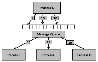
Fig 8 - Example
Having seen certain information on message queues, now it is time to check for the system call (System V) which supports the message queues.
To perform communication using message queues, following are the steps −
Step 1 − Create a message queue or connect to an already existing message queue (msgget()).
Step 2 − Write into message queue (msgsnd()).
Step 3 − Read from the message queue (msgrcv()).
Step 4 − Perform control operations on the message queue (msgctl()).
Now, let us check the syntax and certain information on the above calls..
#include <sys/types.h>
#include <sys/ipc.h>
#include <sys/msg.h>
int msgget(key_t key, int msgflg)
This system call creates or allocates a System V message queue. Following arguments need to be passed −
Note − Refer earlier sections for details on permissions.
This call would return a valid message queue identifier (used for further calls of message queue) on success and -1 in case of failure. To know the cause of failure, check with errno variable or perror() function.
Various errors with respect to this call are EACCESS (permission denied), EEXIST (queue already exists can’t create), ENOENT (queue doesn’t exist), ENOMEM (not enough memory to create the queue), etc.
#include <sys/types.h>
#include <sys/ipc.h>
#include <sys/msg.h>
int msgsnd(int msgid, const void *msgp, size_t msgsz, int msgflg)
This system call sends/appends a message into the message queue (System V). Following arguments need to be passed −
struct msgbuf {
long mtype;
char mtext[1];
};
The variable mtype is used for communicating with different message types, explained in detail in msgrcv() call. The variable mtext is an array or other structure whose size is specified by msgsz (positive value). If the mtext field is not mentioned, then it is considered as zero size message, which is permitted.
This call would return 0 on success and -1 in case of failure. To know the cause of failure, check with errno variable or perror() function.
#include <sys/types.h>
#include <sys/ipc.h>
#include <sys/msg.h>
int msgrcv(int msgid, const void *msgp, size_t msgsz, long msgtype, int msgflg)
This system call retrieves the message from the message queue (System V). Following arguments need to be passed −
struct msgbuf {
long mtype;
char mtext[1];
};
The variable mtype is used for communicating with different message types. The variable mtext is an array or other structure whose size is specified by msgsz (positive value). If the mtext field is not mentioned, then it is considered as zero size message, which is permitted.
1) The third argument, msgsz, is the size of the message received (message should end with a null character)
2) The fouth argument, msgtype, indicates the type of message −
3) The fifth argument, msgflg, indicates certain flags such as IPC_NOWAIT (returns immediately when no message is found in the queue or MSG_NOERROR (truncates the message text if more than msgsz bytes)
This call would return the number of bytes actually received in mtext array on success and -1 in case of failure. To know the cause of failure, check with errno variable or perror() function.
#include <sys/types.h>
#include <sys/ipc.h>
#include <sys/msg.h>
int msgctl(int msgid, int cmd, struct msqid_ds *buf)
This system call performs control operations of the message queue (System V). Following arguments need to be passed −
IPC_STAT − Copies information of the current values of each member of struct msqid_ds to the passed structure pointed by buf. This command requires read permission on the message queue.
IPC_SET − Sets the user ID, group ID of the owner, permissions etc pointed to by structure buf.
IPC_RMID − Removes the message queue immediately.
IPC_INFO − Returns information about the message queue limits and parameters in the structure pointed by buf, which is of type struct msginfo
MSG_INFO − Returns an msginfo structure containing information about the consumed system resources by the message queue.
This call would return the value depending on the passed command. Success of IPC_INFO and MSG_INFO or MSG_STAT returns the index or identifier of the message queue or 0 for other operations and -1 in case of failure. To know the cause of failure, check with errno variable or perror() function.
Having seen the basic information and system calls with regard to message queues, now it is time to check with a program.
Let us see the description before looking at the program −
Step 1 − Create two processes, one is for sending into message queue (msgq_send.c) and another is for retrieving from the message queue (msgq_recv.c)
Step 2 − Creating the key, using ftok() function. For this, initially file msgq.txt is created to get a unique key.
Step 3 − The sending process performs the following.
Step 4 − In the receiving process, performs the following.
To simplify, we are not using the message type for this sample. Also, one process is writing into the queue and another process is reading from the queue. This can be extended as needed i.e., ideally one process would write into the queue and multiple processes read from the queue.
Now, let us check the process (message sending into queue) – File: msgq_send.c
/* Filename: msgq_send.c */
#include <stdio.h>
#include <string.h>
#include <stdlib.h>
#include <errno.h>
#include <string.h>
#include <sys/types.h>
#include <sys/ipc.h>
#include <sys/msg.h>
#define PERMS 0644
struct my_msgbuf {
long mtype;
char mtext[200];
};
int main(void) {
struct my_msgbuf buf;
int msqid;
int len;
key_t key;
system("touch msgq.txt");
if ((key = ftok("msgq.txt", 'B')) == -1) {
perror("ftok");
exit(1);
}
if ((msqid = msgget(key, PERMS | IPC_CREAT)) == -1) {
perror("msgget");
exit(1);
}
printf("message queue: ready to send messages.\n");
printf("Enter lines of text, ^D to quit:\n");
buf.mtype = 1; /* we don't really care in this case */
while(fgets(buf.mtext, sizeof buf.mtext, stdin) != NULL) {
len = strlen(buf.mtext);
/* remove newline at end, if it exists */
if (buf.mtext[len-1] == '\n') buf.mtext[len-1] = '\0';
if (msgsnd(msqid, &buf, len+1, 0) == -1) /* +1 for '\0' */
perror("msgsnd");
}
strcpy(buf.mtext, "end");
len = strlen(buf.mtext);
if (msgsnd(msqid, &buf, len+1, 0) == -1) /* +1 for '\0' */
perror("msgsnd");
if (msgctl(msqid, IPC_RMID, NULL) == -1) {
perror("msgctl");
exit(1);
}
printf("message queue: done sending messages.\n");
return 0;
}
Compilation and Execution Steps-
message queue: ready to send messages.
Enter lines of text, ^D to quit:
this is line 1
this is line 2
message queue: done sending messages.
Following is the code from message receiving process (retrieving message from queue) – File: msgq_recv.c
/* Filename: msgq_recv.c */
#include <stdio.h>
#include <stdlib.h>
#include <errno.h>
#include <sys/types.h>
#include <sys/ipc.h>
#include <sys/msg.h>
#define PERMS 0644
struct my_msgbuf {
long mtype;
char mtext[200];
};
int main(void) {
struct my_msgbuf buf;
int msqid;
int toend;
key_t key;
if ((key = ftok("msgq.txt", 'B')) == -1) {
perror("ftok");
exit(1);
}
if ((msqid = msgget(key, PERMS)) == -1) { /* connect to the queue */
perror("msgget");
exit(1);
}
printf("message queue: ready to receive messages.\n");
for(;;) { /* normally receiving never ends but just to make conclusion
/* this program ends wuth string of end */
if (msgrcv(msqid, &buf, sizeof(buf.mtext), 0, 0) == -1) {
perror("msgrcv");
exit(1);
}
printf("recvd: \"%s\"\n", buf.mtext);
toend = strcmp(buf.mtext,"end");
if (toend == 0)
break;
}
printf("message queue: done receiving messages.\n");
system("rm msgq.txt");
return 0;
}
Compilation and Execution Steps-
message queue: ready to receive messages.
recvd: "this is line 1"
recvd: "this is line 2"
recvd: "end"
message queue: done receiving messages.
Key takeaway-
Process Queues
The Operating system manages various types of queues for each of the process states. The PCB related to the process is also stored in the queue of the same state. If the Process is moved from one state to another state then its PCB is also unlinked from the corresponding queue and added to the other state queue in which the transition is made.
There are the following queues maintained by the Operating system.
Introduction:
In this unit, you will learn how to add interrupt and exception support to your multicycle CPU design. For additional information, please refer section 5.6 and appendix A in the Hennessy and Patterson textbook. Note: you will only be implementing a subset of the exception and interrupt functionality of the MIPS architecture. Therefore, use this page as your definitive source of information regarding this unit.
Exceptions and Interrupts defined:
Exceptions and interrupts are unexpected events that disrupt the normal flow of instruction execution. An exception is an unexpected event from within the processor. An interrupt is an unexpected event from outside the processor. You are to implement exception and interrupt handling in your multicycle CPU design.
When an exception or interrupt occurs, the hardware begins executing code that performs an action in response to the exception. This action may involve killing a process, outputting a error message, communicating with an external device, or horribly crashing the entire computer system by initiating a "Blue Screen of Death" and halting the CPU. The instructions responsible for this action reside in the operating system kernel, and the code that performs this action is called the interrupt handler code. You can think of handler code as an operating system subroutine. After the handler code is executed, it may be possible to continue execution after the instruction where the execution or interrupt occurred.
Exceptions: Types
For your project, there are three events that will trigger an exception: arithmetic overflow, undefined instruction, and system call.
Arithmetic overflow occurs during the execution of an add, addi, or sub instruction. If the result of the computation is too large or too small to hold in the result register, the Overflow output of the ALU will become high during the execute state. This event triggers an exception.
Undefined instruction occurs when an unknown instruction is fetched. This exception is caused by an instruction in the IR that has an unknown opcode or an R-type instruction that has an unknown function code.
System call occurs when the processor executes a syscall instruction. Syscall instructions are used to implement operating system services (functions).
Interrupts:
We also want to have to ability to service external interrupts. This is useful if a device external to the processor needs attention. To do this, we'll add 2 pins to the processor. The first pin, called IRQ (interrupt request), will be an input that will allow an external device to interrupt the processor. Since we don't want the processor to service any external interrupts before it is finished executing the current instruction, we may have to make the external device wait for several clock cycles. Because of this, we need a way to tell the external device that we've serviced its interrupt. We'll solve this problem by adding the second pin, called IACK (interrupt acknowledge), that will be an output. The following waveform defines the timing for external interrupt requests.

Figure 9: Timing diagram for external interrupts
What to do when an exception or interrupt occurs:
When an exception or interrupt occurs, your processor may perform the following actions:
To return from a handler, your processor may perform the following actions:
Dealing with multiple types of exceptions and interrupts
In a situation where multiple types of exceptions and interrupts can occur, there must be a mechanism in place where different handler code can be executed for different types of events. In general, there are two methods for handling this problem: polled interrupts and vectored interrupts.
MIPS uses the first method (polled interrupts), so we'll implement exception handling that way. So, in our case, all exceptions will cause the processor to jump to a "hardwired" instruction address. A sequence of instructions starting at this address will check the cause of the exception and act accordingly. We will set this address to 00000004 (in hex). Also, we'll need to use the Cause register to record the cause of the exception or interrupt before jumping to the handler code.
Cause registerThe Cause register is a 32-bit register, but only certain fields on that register will be used. Bits 1 down to 0 will be set to describe the cause of the last interrupt/exception. The following table codes the interrupt/exception causes:
Number | Name | Description |
00 | INT | External Interrupt |
01 | IBUS | Instruction bus error (invalid instruction) |
10 | OVF | Arithmetic overflow |
11 | SYSCALL | System call |
Disabling interrupts and exceptions
We require a way to disable interrupts and exceptions. This is necessary to prevent exceptions and interrupts from occuring during handler execution. In order to be able to do this, we need an additional register that can be used to mask exception and interrupt types. This is called the Status register.
Status registerThe status register is also a 32-bit register. It too, only has certain fields that are used by the processor. Bits 3 down to 0 will define masks for the three types of interrupts/exceptions. If an interrupt/exception occurs when its mask bit is current set to 0, then the interrupt/exception will be ignored. The mask bits are used according to the following table:
Bit | Interrupt/exception |
3 | INT |
2 | IBUS |
1 | OVF |
0 | SYSCALL |
Control for exceptions
You will need to add control and datapaths to support exceptions and interrupts. When an exception or interrupt occurs, the following must be done:
EPC <= PC
Cause <= (cause code for event)
Status <= Status << 4
PC <= (handler address)
To return from an exception or datapath, the following must be done:
PC <= EPC
Status <= Status >> 4
You will also have to add control to support four additional instructions, mfc0, mtc0, syscall, and rte.
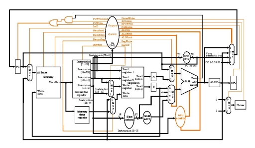
Figure 10: Example top-level block diagram with exception handling hardware added. Note: this design doesn't include the Status register and doesn't use the Cause register the same way we are.
Additional instructions needed:
Several instructions must be added to your instruction set in order to use the interrupt/exception functionality of your processor. These instructions are mfc0 rt,rd and mtc0 rd,rt, which stand for "move from coprocessor 0" and "move from coprocessor 0". The new registers that facilite interrupt and exception handling, Status, Cause, and EPC, can be accessed via these instructions. These new instructions transfer data between the exception registers and the general-purpose registers. Also, you will need the syscall instruction. These instructions are encoded in the following way:
syscall
Executes a system call. The system call number should be set in register $v0 prior to executing the system call.
31-26 | 25-6 | 5-0 |
000000 | 00000000000000000000 | 001100 |
rfe
Return from exception.
31-26 | 25 | 24-6 | 5-0 |
010000 | 1 | 0000000000000000000 | 010000 |
mfc0 rd, rt
Moves data from coprocessor 0 register rt to general purpose register rd.
31-26 | 25-21 | 20-16 | 15-11 | 10-0 |
010000 | 00000 | rt | rd | 00000000000 |
mtc0 rd, rt
Moves data from general purpose register rt to coprocessor 0 register rd.
31-26 | 25-21 | 20-16 | 15-11 | 10-0 |
010000 | 00100 | rt | rd | 00000000000 |
The following table defines coprocessor 0's register set:
Register name | Register number | Usage |
Status | 12 | Interrupt mask and enable bits |
Cause | 13 | Exception type |
EPC | 14 | Register containing the following address of the instruction where the exception occurred |
Key takeaway
Introduction:
In this unit, you will learn how to add interrupt and exception support to your multicycle CPU design. For additional information, please refer section 5.6 and appendix A in the Hennessy and Patterson textbook. Note: you will only be implementing a subset of the exception and interrupt functionality of the MIPS architecture. Therefore, use this page as your definitive source of information regarding this unit.
What is Dynamic Memory Allocation?
Resources are always a premium. We have strived to achieve better utilization of resources at all times; that is the premise of our progress. Related to this pursuit, is the concept of memory allocation.
Memory has to be allocated to the variables that we create, so that actual variables can be brought to existence. Now there is a constraint as how we think it happens, and how it actually happens.
How computer creates a variable?
When we think of creating something, we think of creating something from the very scratch, while this isn’t what actually happens when a computer creates a variable ‘X’; to the computer, is more like an allocation, the computer just assigns a memory cell from a lot of pre-existing memory cells to X. It’s like someone named ‘RAJESH’ being allocated to a hotel room from a lot of free or empty pre-existing rooms. This example probably made it very clear as how the computer does the allocation of memory.
Now, what is Static Memory Allocation? When we declare variables, we actually are preparing all the variables that will be used, so that the compiler knows that the variable being used is actually an important part of the program that the user wants and not just a rogue symbol floating around. So, when we declare variables, what the compiler actually does is allocate those variables to their rooms (refer to the hotel analogy earlier). Now, if you see, this is being done before the program executes, you can’t allocate variables by this method while the program is executing.
// All the variables in below program // are statically allocated. void fun() { int a; } int main() { int b; int c[10] } |
Why do we need to introduce another allocation method of this just gets the job done? Why would we need to allocate memory while the program is executing? Because, even though it isn’t blatantly visible, not being able to allocate memory during run time precludes flexibility and compromises with space efficiency. Specially, those cases where the input isn’t known beforehand, we suffer in terms of inefficient storage use and lack or excess of slots to enter data (given an array or similar data structures to store entries). So, here we define Dynamic Memory Allocation: The mechanism by which storage/memory/cells can be allocated to variables during the run time is called Dynamic Memory Allocation (not to be confused with DMA). So, as we have been going through it all, we can tell that it allocates the memory during the run time which enables us to use as much storage as we want, without worrying about any wastage.
Dynamic memory allocation is the process of assigning the memory space during the execution time or the run time.
Reasons and Advantage of allocating memory dynamically:
int main() { // Below variables are allocated memory // dynamically. int *ptr1 = new int; int *ptr2 = new int[10];
// Dynamically allocated memory is // deallocated delete ptr1; delete [] ptr2; } |
There are two types of available memories- stack and heap. Static memory allocation can only be done on stack whereas dynamic memory allocation can be done on both stack and heap. An example of dynamic allocation to be done on the stack is recursion where the functions are put into call stack in order of their occurrence and popped off one by one on reaching the base case. Example of dynamic memory allocation on the heap is:
int main() { // Below variables are allocated memory // dynamically on heap. int *ptr1 = new int; int *ptr2 = new int[10];
// Dynamically allocated memory is // deallocated delete ptr1; delete [] ptr2; } |
While allocating memory on heap we need to delete the memory manually as memory is not freed(deallocated) by the compiler itself even if the scope of allocated memory finishes(as in case of stack).
To conclude the above topic, static memory is something that the compiler allocates in advance. While dynamic memory is something that is controlled by the program during execution. The program may ask more of it or may delete some allocated.
Fixed Partitioning
The earliest and one of the simplest technique which can be used to load more than one processes into the main memory is Fixed partitioning or Contiguous memory allocation.
In this technique, the main memory is divided into partitions of equal or different sizes. The operating system always resides in the first partition while the other partitions can be used to store user processes. The memory is assigned to the processes in contiguous way.
In fixed partitioning,
There are various cons of using this technique.
1. Internal Fragmentation:
If the size of the process is lesser then the total size of the partition then some size of the partition get wasted and remain unused. This is wastage of the memory and called internal fragmentation.
As shown in the image below, the 4 MB partition is used to load only 3 MB process and the remaining 1 MB got wasted.
2. External Fragmentation:
The total unused space of various partitions cannot be used to load the processes even though there is space available but not in the contiguous form.
As shown in the image below, the remaining 1 MB space of each partition cannot be used as a unit to store a 4 MB process. Despite of the fact that the sufficient space is available to load the process, process will not be loaded.
3. Limitation on the size of the process:
If the process size is larger than the size of maximum sized partition then that process cannot be loaded into the memory. Therefore, a limitation can be imposed on the process size that is it cannot be larger than the size of the largest partition.
4. Degree of multiprogramming is less:
By Degree of multi programming, we simply mean the maximum number of processes that can be loaded into the memory at the same time. In fixed partitioning, the degree of multiprogramming is fixed and very less due to the fact that the size of the partition cannot be varied according to the size of processes.
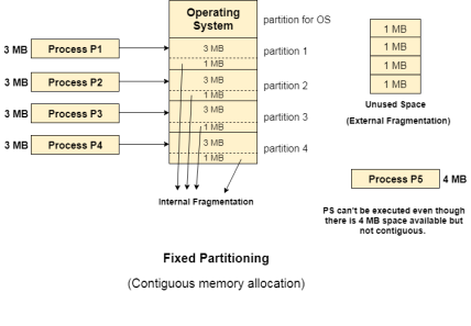
Fig 11 – Contiguous memory allocation
Dynamic Partitioning
Dynamic partitioning tries to overcome the problems caused by fixed partitioning. In this technique, the partition size is not declared initially. It is declared at the time of process loading.
The first partition is reserved for the operating system. The remaining space is divided into parts. The size of each partition will be equal to the size of the process. The partition size varies according to the need of the process so that the internal fragmentation can be avoided.
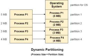
Fig 12 – Dynamic partitioning
Advantages of Dynamic Partitioning over fixed partitioning-
1. No Internal Fragmentation:
Given the fact that the partitions in dynamic partitioning are created according to the need of the process, It is clear that there will not be any internal fragmentation because there will not be any unused remaining space in the partition.
2. No Limitation on the size of the process:
In Fixed partitioning, the process with the size greater than the size of the largest partition could not be executed due to the lack of sufficient contiguous memory. Here, In Dynamic partitioning, the process size can't be restricted since the partition size is decided according to the process size.
3. Degree of multiprogramming is dynamic:
Due to the absence of internal fragmentation, there will not be any unused space in the partition hence more processes can be loaded in the memory at the same time.
Disadvantages of dynamic partitionining-
External Fragmentation:
Absence of internal fragmentation doesn't mean that there will not be external fragmentation.
Let's consider three processes P1 (1 MB) and P2 (3 MB) and P3 (1 MB) are being loaded in the respective partitions of the main memory.
After some time P1 and P3 got completed and their assigned space is freed. Now there are two unused partitions (1 MB and 1 MB) available in the main memory but they cannot be used to load a 2 MB process in the memory since they are not contiguously located.
The rule says that the process must be contiguously present in the main memory to get executed. We need to change this rule to avoid external fragmentation.
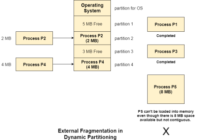
Fig 13 – External fragmentation in dynamic partitioning
Complex Memory Allocation:
In Fixed partitioning, the list of partitions is made once and will never change but in dynamic partitioning, the allocation and deallocation is very complex since the partition size will be varied every time when it is assigned to a new process. OS has to keep track of all the partitions.
Due to the fact that the allocation and deallocation are done very frequently in dynamic memory allocation and the partition size will be changed at each time, it is going to be very difficult for OS to manage everything.
Memory Management Hardware
Memory Hierarchy-
Computers have several different types of memory. This memory is often viewed as a hierarchy as shown below.
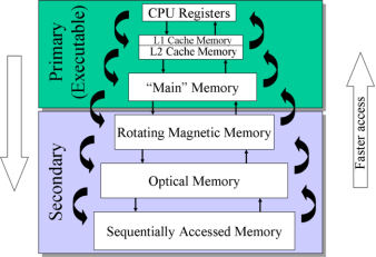
Fig 14 - Memory
Our main concern here will be the computer’s main or RAM memory. The cache memory is important because it boost’s the speed of accessing memory, but it is managed entirely by the hardware. The rotating magnetic memory or disk memory is used by the Virtual Memory Management.
Memory Management Unit:
As a program runs, the memory addresses that it uses to reference its data is the logical address. The real time translation to the physical address is performed in hardware by the CPU’s Memory Management Unit (MMU). The MMU has two special registers that are accessed by the CPU’s control unit. A data to be sent to main memory or retrieved from memory is stored in the Memory Data Register (MDR). The desired logical memory address is stored in the Memory Address Register (MAR). The address translation is also called address binding and uses a memory map that is programmed by the operating system.
Note-
The job of the operating system is to load the appropriate data into the MMU when a processes is started and to respond to the occasional Page Faults by loading the needed memory and updating the memory map.
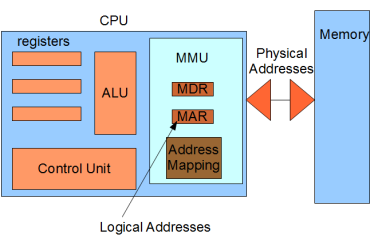
Fig 14 – Logical address
Before memory addresses are loaded on to the system bus, they are translated to physical addresses by the MMU.
Key takeaway
What is Dynamic Memory Allocation?
Resources are always a premium. We have strived to achieve better utilization of resources at all times; that is the premise of our progress. Related to this pursuit, is the concept of memory allocation.
Memory has to be allocated to the variables that we create, so that actual variables can be brought to existence. Now there is a constraint as how we think it happens, and how it actually happens.
Text Books:
1. Operating System Concepts - Abraham Silberschatz, Peter B. Galvin & Grege Gagne (Wiley)
2. Operating Systems - A Concept Based approach - Dhananjay M Dhamdhere (TMGH).
Reference Books:
1. Unix Concepts and Applications – Sumtabha Das (TMGH).
2) Operating System : Concepts and Design - Milan Milenkovic ( TMGH)
3) Operating System with case studies in Unix, Netware and Windows NT - Achyut S. Godbole (TMGH).