UNIT 1
Scales, Plane Scale, Diagonal Scale Practices
Scales
A scale is defined as the ratio of the linear dimensions of the object as represented in a drawing to the actual dimensions of the same.
Necessity
- Drawings drawn with the same size as the objects are called full sized drawing.
- It is not convenient, always, to draw drawings of the object to its actual size. e.g. Buildings, Heavy machines, Bridges, Watches, Electronic devices etc.
- Hence scales are used to prepare drawing at
Full size
Reduced size
Enlarged size
Types of Scale
- Engineers Scale :
The relation between the dimension on the drawing and the actual dimension of the object is mentioned numerically (like 10 mm = 15 m).
Mechanical Engineers Scale:
These are divided and numbered in such a way that fractions of inches represent inches. The most common ranges are 1/8, 1/4, 1/2, and 1 in. To the inch. These scales are known as the size scales because the reduced size also represents the ratio of size, as for example one-eighth size.
Mechanical engineer's scales are almost always "full divided"; that is, the smallest divisions run throughout the entire length.
They are generally graduated with the marked divisions numbered from right to left, as well as from left to right, as shown in Figure Mechanical engineer's scales are used mostly for drawings of machine parts and small structures where the drawing size is more than one-eighth the size of the actual object.
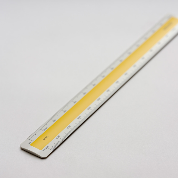
Civil Engineers Scale:
These are divided into decimals with divisions ranging from 10, 20, 30, 40, 50, 60, and 80 to the inch. Such a scale is usually full divided and is sometimes numbered both from left to right and right to leave. Civil engineer's scales are most used for plotting and drawing maps, although they are convenient for any work where divisions of the inch, in tenths is required.
2. Graphical Scale:
Scale is drawn on the drawing itself. This takes care of the shrinkage of the engineer’s scale when the drawing becomes old.
Types of Graphical Scale
- Plain Scale
- Diagonal Scale
- Vernier Scale
- Comparative scale
- Plain Scale
- A plain scale consists of a line divided into suitable number of equal units. The first unit is subdivided into smaller parts.
- The zero should be placed at the end of the 1st main unit.
- From the zero mark, the units should be numbered to the right and the sub-divisions to the left.
- The units and the subdivisions should be labeled clearly.
2. Diagonal Scale
- Through Diagonal scale, measurements can be up to second decimal (e.g. 4.35).
- Diagonal scales are used to measure distances in a unit and its immediate two subdivisions; e.g. Dm, cm & mm, or yard, foot & inch.
- Diagonal scale can measure more accurately than the plain scale.
3. Vernier Scales
- Similar to Diagonal scale, Vernier scale is used for measuring up to second decimal.
- A Vernier scale consists of
(i) a primary scale and
(ii) a vernier.
- The primary scale is a plain scale fully divided into minor divisions.
- The graduations on the vernier are derived from those on the Least count (LC) is the minimum distance that can be measured.
Curves used in engineering practice:
The profile of number of objects consists of various types of curves.
1. Conic sections:
The section obtained by intersection, of a right circular cone by a plane in different positions relative to the axis of the cone are called conics.
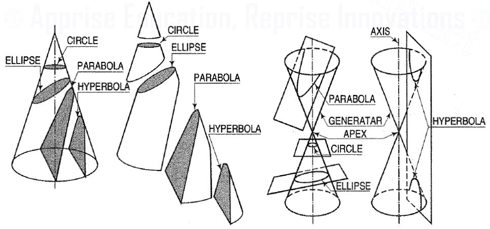
Conic sections are always "smooth". More precisely, they never contain any inflection points. This is important for many applications, such as aerodynamics, civil engineering, mechanical engineering, etc.
The conic may be defined as the locus of a point in a plane, wherein the ratio of its distance from a fixed point and a fixed straight line is always constant. The fixed point is called the focus and the fixed line, the directrix.
The ratio  is called eccentricity and is denoted by ‘e’. It is always less the 1 for ellipse, equal to 1 for parabola and greater than 1 for hyperbola.
1. Ellipse:
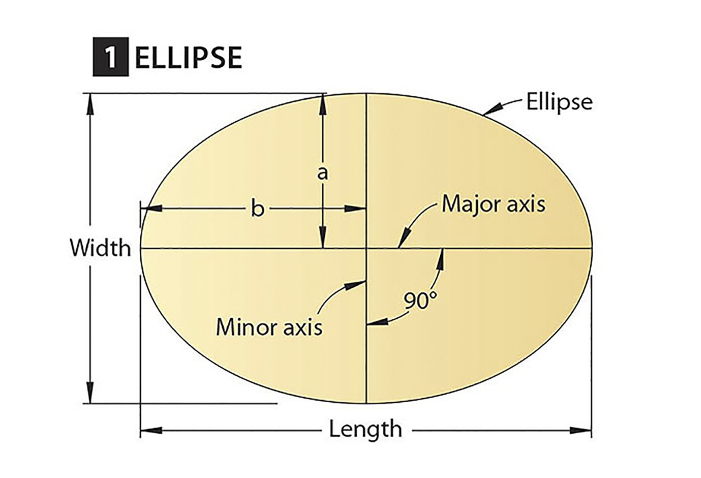
Use of elliptical curves is made in arches, bridges, dams, monuments, man holes, etc. Mathematically an ellipse can be described by equation .
.
Here ‘a’ and ‘b’ are half the length of major and minor axes of ellipse and x and y are co-ordinates.
2. Parabola:
Use of parabolic curves is made in arches, bridges, sound reflectors, light reflectors, etc. Mathematically it can be described by an equation  or
or .
.
Involute:
The involute is a curve traced out by an end of a piece of thread unwound from a circle or a polygon, the thread being kept tight. It may also be defined as a curve traced out by a point in a straight line which rolls without slipping along a circle or a polygon.
It is used as teeth profile of gear wheel.
Mathematically it can be described as by  ,
,  , where “r” is the radius of the circle.
Spiral:
If a line rotates in a plane about one of its ends and if at the same time, a point moves along the line continuously in one direction, the curve traced out by the moving point is called a spiral. The point about which the line rotates is called a pole.
The line joining any point on the curve with the pole is called the radius vector and the angle between this line and the line in its initial position is called the vectorial angle.
Archemedian spiral:
It is a curve traced out by a point moving in such a way that its movement towards and away from the pole is uniform with the increase of the vectorial angle from the starting line.
The use of this curve is made in teeth profiles of helical gears, profile of cams, etc.
Oblong method (Given major and minor axes)
Step 1: Draw the major axis V1, V2 of the given length and minor axis V3, V4 meeting at midpoint O.
Step 2: Take half of the major axis as radius and from any of the minor axis ends (V3 or V4) as centre, cut the major axis on either side of the minor axis to get two points called foci. Name the foci F1 F2 respectively.
Step 3: Enclose the 2 axes in a rectangle A, B, C, D, including all the four vertices V1, V2, V3, V4, such that the length of the rectangle is equal to the major axis length and width equal to minor axis length. This rectangle A, B, C, D, comprises four similar rectangles V1 – O – V3 – D, O – V2 – C, V3, V2 – O – V4 – B, V4 – O – V1 – A respectively of lengths equal to half of major axis length and width equal to half of minor axis length, as shown in Figure 1.3.1
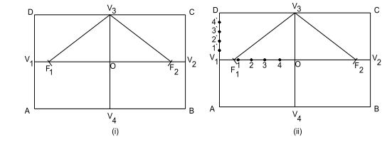

Step 4: Consider any rectangle (say V1 – O – V3 – D ) among the four similar rectangles. Divide its length V1 – O and width V1 – D into equal parts of the same number. Name the divisions 1, 2, 3,… and 1¢, 2¢, 3¢,… on the length and width divisions respectively. Start naming the divisions starting only from the major axis vertices, as shown in Fig. 3.1.1 (ii) .
Step 5: Join division points 1¢, 2¢, 3¢,… on the rectangular width V1 – O to the minor axis vertex V3 which is on the opposite width side, with straight lines to get 1¢ – V3, 2¢ – V3, 3¢ – V3 … lines. Similarly, join division points 1, 2, 3,… on the rectangular length V1 – O to the other minor axis vertex V4 with straight lines to get 1 – V4, 2 – V4, 3 – V4 … lines, as shown in Fig. 3.1.2 (iii).
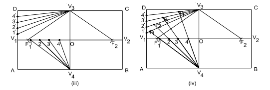

Figure 3.1.2
Step 6: Extend the lines 1 – V4, 2 – V4, 3 – V4 …passing from rectangular length divisions only, onto the corresponding numbered lines joined to the other minor axis vertex, i.e., onto 1¢ – V3, 2¢ – V3, 3¢ – V3 … lines to get intersection points. Name these intersection points P1, P2, P3, … as shown in Fig. 3.1.2 (iv).
Step 7: Repeat steps 4 to 6 on remaining similar rectangles to generate points Q1, Q2, Q3, … , R1, R2, R3, … , S1, S2, S3, … respectively. Join all these intersection points with a smooth curve to get the required ellipse, as shown in Fig. 3.1.3 (v & vi).
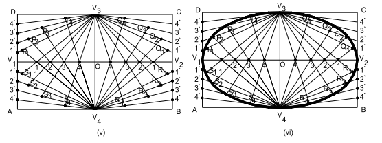

Rectangle method (Given base and axis height of the parabola)
Step 1: Draw the given base as horizontal line and at the midpoint of base, draw axis vertically of the given height. Name the base line as AB and axis line as CD, respectively. Hence, C is the midpoint of AB.
Step 2: Enclose base AB and axis CD in two equal rectangles ACDE and CBFD such that axis CD is the common side for both these rectangles.
Step 3: In rectangle ACDE, divide the sides AE and AC into the same number of equal parts. Name then 1, 2, 3,…, and 1¢, 2¢, 3¢,…, respectively starting from the rectangle base corner A , as shown in Fig. 3.1.4 (i).
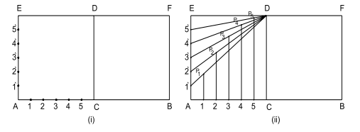

Step 4: Join the division on vertical side AE to axis line point D, to obtain the lines D – 1, D – 2, D – 3, ….
Step 5: Draw vertical lines from divisions on the side AC, so that these vertical lines meet the corresponding D – 1, D – 2, D – 3, ….lines. Name the intersection points of the vertical line with D – 1, D – 2, D – 3, ….lines as P1, P2, P3,… as shown in Fig. 3.1.4 (ii).
Step 6: Repeat step 3 to step 5 in the other rectangle CBFD also, to get the intersection points R1, R2, R3,…to complete the parabola, with the given base and height, as shown in Fig. 3.1.5 (iii).
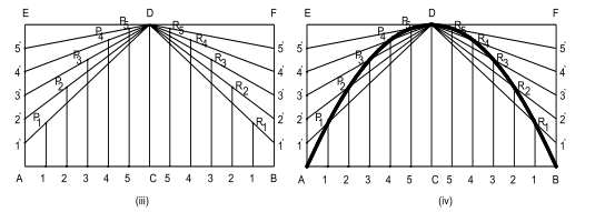

Step 7: Join all these intersection point P1, P2, P3,… & R1, R2, R3,…including the base corner points and axis line end point A, B, D respectively, to generate the required parabola, as shown in Fig. 3.1.5 (iv).