UNIT 4
Projection Of Plane Surfaces And Solids
Projection of Plane surfaces and solids- Projection of Polygonal surfaces and circular lamina inclined to both planes.
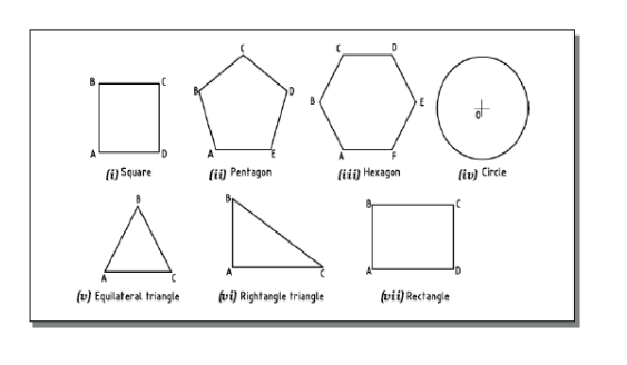
A plane is a two dimensional object having length and breadth only. Its thickness is always neglected. Various shapes of plane figures are considered such as square, rectangle, circle, pentagon, hexagon, etc.

What is usually asked in the problem?
- To draw their projections means F.V, T.V. & S.V.
What will be given in the problem?
- Description of the plane figure.
- It’s position with HP and VP.

Projection of simple solids such as Prisms, Pyramids, Cylinders and Cones with their axes perpendicular to anyone of the Principal planes and inclined to the other.
A solid has three dimensions, viz. Length, breadth and thickness. To represent a solid on a flat surface having only length and breadth, at least two orthographic views are necessary.
Types of Solids
Solids may be divided into two main groups:
- Polyhedron
- Solids of revolution.
Polyhedron: A polyhedron is defined as a solid bounded by planes called faces. When all the faces are equal and regular, the polyhedron is said to be regular.
- Tetrahedron : It has four equal faces, each an equilateral triangle.
- Cube or Hexahedron : It has six faces, all equal squares.
- Octahedron : It has eight equal equilateral triangles as faces
- Dodecahedron : It has twelve equal and regular pentagons as faces.
Prism : This is a polyhedron having two equal and similar faces called its ends or bases, parallel to each other and joined by other faces, which are parallelograms. The imaginary line joining the centers of the bases is called the axis. A right and regular prism has its axis perpendicular to the bases. All its faces are equal rectangles.
Pyramid: This is a polyhedron having a plane figure as a base and a number of triangular faces meeting at a point called the vertex or apex. The imaginary line joining the apex with the centre of the base is its axis. A right and regular pyramid has its axis perpendicular to the base, which is a regular plane figure. Its faces are all equal isosceles triangles.
Solids of Revolution Definition: Solids which are generated by rotating a plane surface about one of its sides
Three Types
a) Cylinder
b) Cone
c) Sphere
a) Cylinder
A right circular cylinder is a solid generated by the revolution of a rectangle about one of its sides, which remains fixed. It has two equal circular bases. The line joining the centers of the bases is the axis. It is perpendicular to the bases.
b. Cone : A right circular cone is a solid generated by the revolution of right-angled triangles about one of its perpendicular sides, which is fixed.
It has one circular base. Its axis joins the apex with the centre of the base to which it is perpendicular. Straight lines drawn from the apex to the circumference of the base-circle are all equal and are called generators of the cone.
Projections of Solids in Simple Positions
A solid in simple position may have its axis perpendicular to one reference plane or parallel to both.
When the axis is perpendicular to one reference plane, it is parallel to the other. Also, when the axis of a solid is perpendicular to a plane, its base will be parallel to that plane.
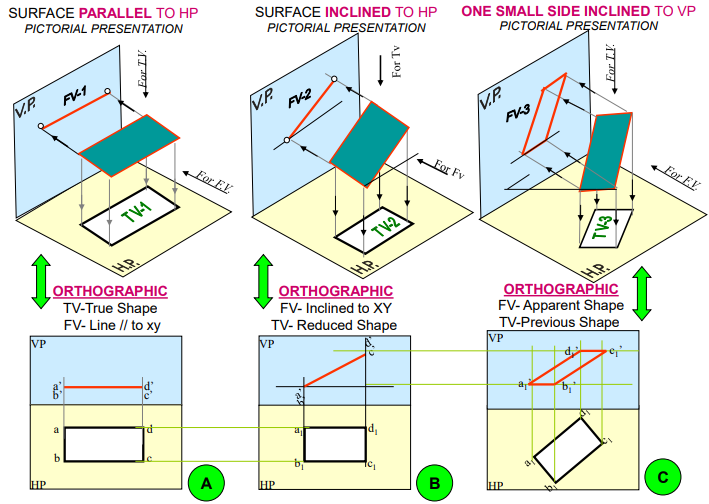
We have already seen that when a plane is parallel to a reference plane, its projection on that plane shows its true shape and size .
Therefore, the projection of a solid on the plane to which its axis is perpendicular will show the true shape and size of its base. Hence, when the axis is perpendicular to the ground, i.e. to the H.P., the top view should be drawn first and the front view projected from it. When the axis is perpendicular to the V.P., beginning should be made with the front view. The top view should then be projected from it. When the axis is parallel to both the H.P. And the V.P., neither the top view nor the front view will show the actual shape of the base. In this case, the projection of the solid on an auxiliary plane perpendicular to both the planes,
The side view must be both the planes, viz. The side view must be drawn first. The front view and the top view are then projected from the side view. The projections in such cases may also be drawn in two stages.