UNIT 5
Transformers
A transformer is a stationary device which works on the principle of Mutual Induction. It is used to transform electric power from one circuit to another having same frequency. It can lower or higher the value of voltage in any circuit but in correspondence to change in current.
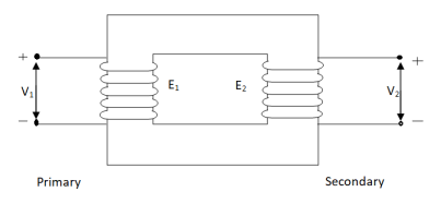
An ideal transformer has no losses i.e. its winding have no magnetic leakage and no ohmic resistance. Hence, an ideal transformer has only two purely inductive coils wound on a loss-free core.
Fig. Ideal Transformer
For above transformer when secondary is open and primary is having input sinusoidal voltage V1. An alternating, current flows due to difference in potential. As primary coil is purely inductive so, Iµ current is drawn through it. This current is very small and logs V1 by 900.
The current Iµ produces magnetic flux φ and hence are in same phase. The flux is linked with both the windings and hence, self-induced emf is produced E1 which is equal and opposite of V1. Similarly, E2 is induced in secondary which is mutually induced emf E2 is proportional to rate of change of flux and number of secondary windings.
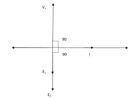
The phasor is shown below.
Phasor for Ideal Transformer
- Types of transformers
Acc to input supply: I phase and  phase
phase
Acc to construction: core and shell type
Acc to 0/P: step up and step down
Construction of transformers (study only for MCQs)
- Laminated steel core
Material used for core is (silicon steel) it is used for its (high permeability) and (low magnetic reluctance)  magnetic field produced is very strong
The core is formed of (stacks of laminated thin steel sheets) which are electrically isolated from each other. They are typically (0.35 to 0.5 mm thick)
We can used 2 ‘L’ shaped sheets or 2  shaped sheets for laminations
Construction and types
- There are 2 types of winding
- Concentric or cylindrical
- Sandwiched type
- Cylindrical
L.V. = low voltage H.V. = high voltage are mounted on same limb to minimum leakage.
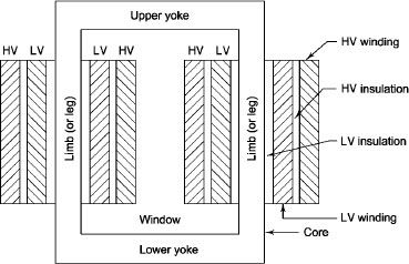
L.V. Winding placed inside and H.V. Winding placed outside with (proper insulation between the winding as it is easy to insulated L.V. Winding) than H.V. Winding.
2. Sandwiched
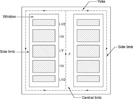
The H.V. And L.V. Winding are divided into no. Of small coils and there, small windings are interleaved.
(the top and bottom winding are L.V. Coils because they are close to core)
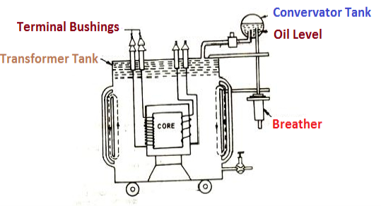
- Transformer tank: wholes assembly of winding and core placed inside the Transformer tank (sheet metal tank) which is filled with Transformer oil or insulating oil which acts as an (insulator or coolant) MCQ
- Transformer oil: (The function of oil is to remove efficiently the heat generated in core and in winding)
- Moisture should not be allowed which creeps the insulation which achieved by closed Transformer tank.
(To increase cooling surface are tubes or fins are provided)
- Conservator tank: above tank T/F tank there is one small tank in which same empty space is always provided above the oil level. (this space is required for oil to expand or contract due to temperature change) MCQ
However, during contraction outside air can have moisture which will deteriorate the insulating properly of oil.
- Breather: the air goes in or out through the breather (To reduce the moisture content of their air. Same drying agents such as (silica gel or) calcium chloride) is used in the breather (The dust particles present in air are also removed by breather)
- Buccholz Relay: (for incipient (slowly increasing) faults
There is pipe connecting rain tank and conservator. On the pipe a protective device called Buccholz Relay is mounted.
When the Transformer is about to be faulty and draw range current the oil becomes very hot and decompose.
During this process different types of gases are liberated (The Bucchoz Relay get operated by these gases) and gives an alarm to the operator. ɡȴ the fault continues to persist then there lay will trip off main circuit breaker to protect the Transformer.
- Explosion Vent:
An explosion Vent or relief value is the bent-up pipe filled on the main tank.
(The explosion vent consists of aluminium of oil) when the T/F becomes faulty the cooling oil get decomposed and various types of gases are liberated
(ɡȴ the gas pressure exodus certain level then the aluminium of oil (diagram) in explosion vent will burst) to release pressure. They will save main tank from getting damaged.
N1 = No of primary turns
N2 = No of secondary turns
Φm = max flux in cone (wb)
Φm = Bm x A
f = Frequency of input(ac) Hz
Average rate of change of flux
= Φm / ¼
= 4 ΦmF volts
Average emf per turn = 4F ΦmV
As Φ varies sinusoidally rms value of induced emf is given as
Form factor = r.m.s value / average value = 1.11
r.m.s value of emf/turn = 1.11 x 4f Φm
= 4.44 f Φm volt
r.m.s value of induced emf in primary winding
= (induced emf/turn) x No of primary turns
E1 = 4.44 fN1 Φm
E1 = 4.44 fN1BmA
r.m.s emf induced in secondary
E2 = 4.44 fN2 Φm
E2 = 4.44 fN2BmA
E1/E2 = N1/N2 = K
K – voltage transformation
(i). If N2 > N1 i.e K > 1 STEP UP TRASFORMER
(II). If N1 > N2 i.e K<1 STEP DOWN TRASFORMER
FOR Ideal Transformer
V1 I1 = V2 I2 = 1/K
Hence, current is inversely proportional to the voltage transformation ratio.
Q1>. A 25 KVA transformer has 500 turns on primary and 50 on secondary. The primary is connected to 2000V, 50 Hz supply. Find full load primary and secondary currents, the secondary emf and max flux in core. Neglect leakage drop and no load primary current.
Sol : K = N2/N1 = 50/500 = 1/10
I1 = 25,000/2000 = 12.5 A
I2 = I1/K = 10 x 12.5 A = 125 A
Emf/turn on primary side = 2000/500 = 4 V
E2 = KE1
E2 = 4 x 50 = 200 v
E1 = 4.44fN1 Φm
2000 = 4.44 x 50 x 500 x Φm
Φm = 18.02 m Wb
Q1>. A 2500/200 V transformer draws a no-load primary current of 0.5 A and absorbs 400 W. Find magnetising and loss currents.
Sol: Iron-loss current = No load input(W) / Primary voltage
= 400/2500 = 0.16 A
I20 = I2w + I2µ
Iµ = √I20 – I2w
= √ (0.5)2 – (0.16)2
Iµ = 0.473 A
When secondary winding is loaded then the current in it is setup(IQ). The current I2 is in phase with V2 if load is non-inductive it lags if load is inductive & leads if load is capacitive.
An mmf is set up at secondary and hence φ2 flux is induced which is in opposition to main flux φ due to I0. The flux φ2 weaken φ and hence primary back emf E1 is reduced. An additional primary current I’2 is introduced exactly at instance when I2 is introduced. So, that magnetic effect of I2 is neutralized by I’2.
Φ2 = φ’2
N2 I2 = N1 I’2
I’2 = N2/N1 x I2 = K2 I2
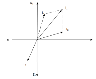
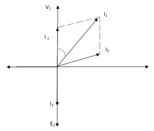
The phasor is shown below,
(a) (b)
Fig. Phasor for Load Transformer
From fig (a) (non – inductive load)
I2 is in phase with E2(=V2)
I’2 is antiphase with but equal in magnitude
I1 is vector sum of I’2 and I0, but lags V1
From fig (b), Inductive load
I2 lags V2
I’2 is not in phase with I2 but equal in magnitude
I1 is vector sum of I’2 & I0 but lags V1
I’2/I2 = I1/I2 = N2/N1 = K
Q>. A 1- φ transformer with ratio of 440/110-V takes a no-load current of 6 A at 0.3 pf lagging. If secondary supplies 120 A at pf of 0.8 lagging. Find current taken by primary.
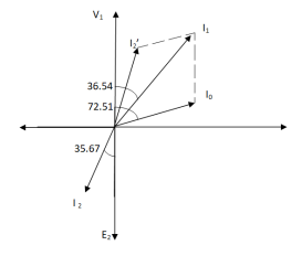
Sol>.
Cos φ2 = 0.8
Φ2 = 36.540
Cos φ0 = 0.3
Φ0 = 72.540
K = V2/V1 = 110/440 = ¼
I’2 = KI2 = 120 x ¼ = 30 A
I0 = 6A
Angle between I0 & I’2
= 72.54 – 36.54
= 35.670
From vector diagram,
I1 = √(62 + 302 + 2 x 6 x 30 cos 35.67)
I1 = 35.05 A
The fundamental principle of induction machine is the creation of rotating and sinusoidally distributed magnetic field in the air gap. Three phase balanced power supply is fed to the three-phase stator winding creates a synchronously rotating magnetic field. Due to relative speed between rotating flux and stationary conductors, an emf is induced. The frequency to induced emf is same as supply frequency.
As shown in below fig.a , the stator field is assumed to clockwise. The relative motion of rotor w.r.t stator is anticlockwise. From Right-hand rule, the direction of induced emf in rotor is outwards. By the effect of combined field as shown in fig b the rotor experiences a force tending to rotate it in clockwise direction. Hence rotor rotates in the same direction as the stator field.
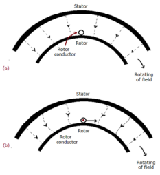
The speed of this rotating field is called synchronous speed. If the rotor is initially stationary, its conductors will be subjected to a changing magnetic field, inducing current in the short-circuited rotor at the same frequency. The interaction of air gap flux and rotor mmf produces torque. At synchronous speed rotor cannot have any torque.
There are two main parts of induction motor:
a) Stator
b) Rotor
a) Stator:
It is stationary part of induction motor. It has number of stampings. It is wound with three phase winding which is fed from 3-phase supply. The number of poles here are defined, they are selected according to the speed required. If required speed is greater than we need less number of poles. The stator produces an alternating flux when fed with 3-phase supply which revolves with synchronous speed(Ns = 120f / P). The synchronous speed is inversely proportional to number of poles.
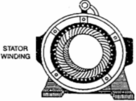
Fig: Stator
b) Rotor: It is rotating part of induction motor. There are two types of rotor
i)Squirrel cage rotor:
The rotor consists of a cylindrical core with parallel slots for carrying the rotor conductor. Each slot has one copper or aluminium bar. Each end of all bars is joined with metal ring. The entire construction resembles a squirrel cage. The rotor is not connected electrically to the supply it has induced current from stator. Almost 90% of induction motors are squirrel cage type. But is has a disadvantage of low starting torque, because the rotor bars are permanently short-circuited.
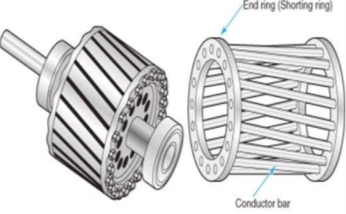
Fig Squirrel cage rotor
Ii) Phase-wound rotor: It has laminated cylindrical core and the windings are uniformly distributed in the slots which are usually star connected. The other three winding terminals are brought out and connected to three insulated slip rings mounted on shaft with brushes resting on them. The three brushes are connected to a 3-phase star-connected rheostat as shown in Figure below.
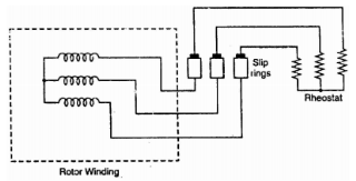
Fig: 3-phase star connected
At starting, the external resistances are included in the rotor circuit to give a large starting torque. These resistances are gradually reduced to zero as the motor runs up to speed. The external resistances are used during starting period only. When the motor attains normal speed, the three brushes are short-circuited so that the wound rotor runs like a squirrel cage rotor.
Slip:
The rotor can never have same speed as that of stator. If it occurs then there will not be relative speed between the two, hence no rotor emf, no rotor current and so no torque to maintain rotation. Due to this reason speed of rotor is always less than the stator field. The difference between the synchronous speed Ns and the actual speed N of the rotor is called as slip.
% slip s=
Therefore, rotor speed N=Ns(1-s).
Frequency of rotor current:
When rotor is stationary its frequency is same as the supply frequency. But when rotor revolves its frequency depends upon the slip-speed. Let frequency of rotor current be f’
Ns-N=
But Ns=

Rotor current have same frequency

=
MMF produced by rotor current:
a) For standstill condition:
Let E2=emf induced per phase of rotor at standstill
R2=resistance per phase of rotor.
X2=reactance per phase of rotor at standstill=2 f1L2
f1L2
Z2=rotor impedance per phase
I2=rotor current per phase
Z2=R2+jX2
 =
=
Power Factor cosφ2= =
=
b) Rotor current at slip s:
Induced emf per phase in rotor winding at slip s is E2s=sE2
Rotor winding reactance per phase at slip s will be X2s=2 f2L=sX2
Rotor winding impedance per phase at slip s is Z2s=R2+jX2s=R2+jsX2
Rotor current at slip s, I2s=
Power factor at slip s is cosφ2s=
Que) The stator of a 3-phase induction motor has 5 slots per pole per phase. If supply frequency is 50Hz. Calculate a) number of stator poles produced and total number of slots in stator. b) Speed of rotating stator flux.?
Sol: a) P=2n=2*5=10 poles
Total number of slots= 5 slots/pole/phase * 10 poles * 3 phase=150
c) Ns= =120x50/10=600rpm
Que) A 3-phase induction motor is wound for 5 poles and is supplied from 50 Hz. Calculate a) synchronous speed b) rotor speed when slip is 4% c) rotor frequency when rotor runs at 500 rpm?
Sol: a) Ns= =120x50/5=1200 rpm
b) rotor speed N=Ns(1-s)=1200(1-0.04)=1152 rpm
c)when rotor speed is 500 rpm, slip s=(Ns-N)/Ns=(1200-500)/1200=0.58
Rotor current frequency f’=sf=0.58x50=29.17 Hz
Que) A 3-phase, 50 Hz,3-pole induction motor has a slip of 4%. Calculate- a) speed of rotor. B) frequency of rotor emf. If the rotor as a resistance of 2ohm, and standstill reactance of 4ohm, calculate the power factor c) at standstill and d) at a speed of 1200rpm?
Sol: Ns= =120x50/3=2000 rpm
a) Speed of rotor N=Ns(1-s)=2000(1-0.04)=1920 rpm
b) Frequency or rotor = f’=sf=0.04x50=2Hz
R2=2ohm, X2=4ohm
Z2=R2+jX2=2+j4=4.47 63.43o ohm
c)Power factor cosφ2=0.44(lag)
Slip at speed 1200rpm s= 2000-1200/2000=0.4
Rotor impedance at slip s=0.4 is
Z2s=R2+jsX2=2+jx0.4x4=2.56 oohm
oohm
Power factor at 1200rpm is cos φ2s=cos38.66o=0.78(lag)
Q) A 3-phase induction motor star connected rotor has an induced emf of 70volts between slip rings at standstill on open circuit. The rotor has a resistance and reactance per phase of 1ohm and 5ohm respectively. Calculate current/phase and power factor when slip rings are short circuited?
Sol: Standstill emf/rotor phase=70/
Rotor impedance/phase= ohm
ohm
Rotor current/phase=40.4/5.09=7.92A
Power factor cosφ=0.99
Que) A 3-phase induction motor star connected rotor has an induced emf of 70volts between slip rings at standstill on open circuit. The rotor has a resistance and reactance per phase of 1ohm and 5ohm respectively. Calculate current/phase and power factor when slip rings are connected to star connected rheostat of 2ohm?
Sol: Rotor resistance/phase=2+1=3 ohm
Rotor impedance/phase= =5.83 ohm
Rotor current/phase= (70/ )/5.83=6.93A
Cosφ=3/5.83=0.514
Que) A 6-pole, 3-phase induction motor operates from a supply whose frequency is 50Hz. Calculate i) speed at which the magnetic field of stator is rotating. Ii)speed of rotor when slip is 4%. Iii)frequency of rotor current when slip is 3%?
Sol: i) Stator revolves at synchronous speed. So, Ns=120f/P=120 x 50/6=1000rpm
Ii)rotor speed N=(1-s) Ns= (1-0.04) x 1000=960rpm
Iii)frequency of rotor current f’=sf=0.03 x 50=90rpm
i) Squirrel cage motor: The rotor in this type of motor is inside so called as squirrel cage motor. The rotor is cylindrical made of highly conductive material. A rotating magnetic field is produced in the stator when the current passes through it. The induced current now flows through the rotor also producing its own magnetic field. The magnetic field produced by stator and rotor produces a torque.
The frequency of rotor current = slip x supply frequency.
The stator has 3-phase windings with a core. They are 1200 apart. The rotor is the part in IM which rotates. It consists of shaft, short circuited aluminium or copper bars. The rotor is laminated to avoid losses like eddy current and hysteresis. A fan is attached to maintain the motor temperature and reduce the heat generated. Bearings are provided as the base for rotor motion, and the bearings keep the smooth rotation of the motor.
Ii) Slip ring IM: It is an asynchronous motor because the motor speed is not equal to the synchronous speed of rotor. The stator has various slots. The rotor is cylindrical core with steel lamination. The rotor has parallel slots and are arranged in 1200 to each other. A rotating magnetic field is produced in the stator when the current passes through it. The induced current now flows through the rotor also producing its own magnetic field. The magnetic field produced by stator and rotor produces a torque.
The slip is nothing but difference between flux speed and rotor speed, for the IM to produce torque there should be some difference between stator field and rotor speed. The slip-rings are electromechanical devices that helps in transmitting power and electrical signals from stationary to rotating components.
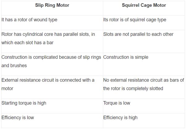
Normally in DC motors we give supply to stator and another supply to rotor though brushes. In IM the working principle is magnetic induction. When the supply is given to stator magnetic flux is generated due to flow of current in coil. The rotor becomes short circuited. The flux cuts the short-circuited coil in rotor. According to Faradays law due to short circuit coil in rotor one more current starts to flow generating another flux. The rotor flux lags the stator flux as is experiences a torque which makes rotor to rotate in the direction of the rotating magnetic field.
3-phase IM
1) They are used in centrifugal pimps.
2) They are used to run conveyor belts.
3) They are used in large blower and fans.
4) They are used in lathe machines.
5) In machine tools.
6) In Large capacity exhaust fans.
7) Oil extracting mills.
8) In lifts and cranes.
9) In textiles and hoist.
1-phase IM
They are used in pumps, compressors, small fans, mixers, toys and High-speed vacuum cleaners. They also used in electric shavers and drilling machines.
It is defined as the luminous flux falling per unit area of surface.
- Inverse square Law:
This law states that the Illuminance (E) at any point on a plane perpendicular to the line joining the point and source is inversely proportional to the square of the distance between the source and plane.
E= 
I: Luminous intensity
We assume a source with luminous intensity I. Considering two radii r1 and r2 having surfaces dA1 and dA2.They are within small angle Ω and luminous flux φ. Both areas receive same luminous flux.
I= for dA1
I=  for dA2
Solid angle for both surfaces
 =
=  =
= 
Illuminance at r1= E1= = I
= I
Illuminance at r2= E2= = I
= I
DA2 =  dA1
dA1
E2= I
So, the above equation now becomes
E2 =  E1
E1
 =
= 
The above equation shows that the illuminance varies inversely as the square of the illuminated point from the source. The relationship is valid for all light sources.
2. Lambert Cosine Law:
The law states that Illuminance at a point on a plane is proportional to the cosine of the angle of light incident.
E=  cos
cos
 = Luminous intensity of source
 = angle between the normal to the plane containing the illuminated point and the line joining the source to the illuminated point
d= distance to illuminated point
The Illuminance or the surface density of the light flux received by an elementary area varies with the distance from the light source and the angle of the elementary area with respect to the direction of the light flux.
When elementary area  A is titled by
  , the flux is
 =
=  x
x  cos
cos =
= cos
cos
Illuminance at 
 =
=  =
=  cos
cos = Emax cos
When all flux is intercepted by larger element 
 =
= 
The illuminance will be
 =
=  =
=  = Emax cos
E= Emax cos
Basic units for measuring the light are
Lumen: The light which is visible by the source emitting it is called Lumen.
Lux: The measure of light over a given surface area.
1 lux= 1ln/m2
Footcandle: One footcandle is equal to one lumen/ square foot
1 footcandle = 10.76lux
The standard values of light needed to design a room a listed in table below
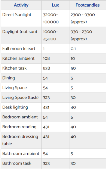
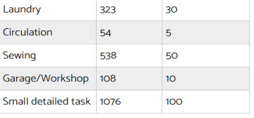
Finding the lumens required:
If some bathroom is 4mx3m. So, the area becomes 12m2. The number of lumens required will be 54x12 (see table above for bathroom ambient) = 648lumens
If we want to light the countertop of kitchen which is 4mx0.5m. The area becomes 2.0m2. The lumens required will be = 2.0x 538 = 1076lumens.
Calculate number of bulbs required:
If LED lights are used and the bulbs used give 330lumens. Then we need 1291/330 = 3.91, which means we need 4 of the bulbs to light the countertop.
Basic requirements for designing of lighting are listed below:
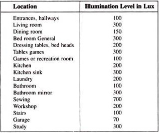
1) Illumination level: For getting clear and proper light required for any room or area inside the house we need to maintain the illumination level. Illumination gives a distributed brightness to the objects. The size of the object to be seen and its distance from the observer-greater the distance of the object from observer and smaller the size of the object, greater will be the illumination required for its proper perception and greater the contrast between the colour of object and its background, greater will be the illuminance.
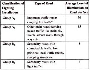
2) Uniformity of Illumination: If the illumination is less or more then the level of brightness a human eye requires normally will change. The human eye can adjust to the surrounding brightness but frequent change can cause fatigue and strain on eyes. The modern trend is thus towards ‘localised lighting plus general lighting’ and towards the adoption of “general lighting oriented towards the working surface” especially in mass production factories, offices, drawing offices, shops etc.
3) Colour of Light: The colour of light plays an important role because for getting the natural sense of what we observe we need to get the proper colour of light on the objects. Daylight fluorescent tubes nowadays make it possible to illuminate economically even large spaces with artificial daylight giving good colour rendering and at sufficiently high level.
4) Shadow: The formation of long ad hard shadows causes fatigue to eyes. If there is no shadow then we face the problem. A certain amount of shadow is desirable in artificial lighting as it helps to give shape to the solid objects and makes them easily recognised. Objects illuminated by shadowless light appear flat and uninteresting, contours are lost, and it is difficult for the eye to form a correct judgement of the shape of an object.
5) Glare: The direct glare from the source of light is most common. A proper adjustment to the glare from light is necessary. When we directly face sun the light is too bright, tolerance to bright light in the intermediate vicinity is made possible by locating them at some height above ordinary range of vision.
6) Mounting Height: In the case of direct lighting, in rooms of large floor area, the luminaries should be mounted as close to the ceiling as possible. Lowering them not only will make the illumination less uniform, but will also bring them more into the field of vision, thus increasing the glare, without causing an appreciable increase in the coefficient of utilization. In the case of indirect and semi-indirect lighting, it would of course be desirable to suspend the luminaries far enough down from the ceiling in order to give reasonably uniform illumination on the ceiling.
7) Spacing of Luminaries: In the case of direct and semi-direct luminaries the ratio of the horizontal spacing between rows to the height of the luminaries above the working plane depends to quite an extent on the candle power-distribution curve of the luminaire. With fluorescent luminaries it is good practice to aim at a value of unity for this ratio, and to set an upper limit of 3/4. In the case of tungsten lamps combined with focusing reflectors, the ratio of spacing to height should be about 0.6.
8) Colour of surrounding walls: If the colour of surrounding walls is not proper than the illumination will be affected. The ceilings and white walls reflect more light than the coloured walls and ceilings.