UNIT 5
Electrical Machines
Consider a stator of an electric motor where three-phase winding is physically distributed in the stator core in such a manner that winding of each phase is separated from other by 120o in space.
Although the vector sum of three currents in a balanced three-phase system is zero at any instant, but the resultant of the magnetic fields produced by the currents is not zero rather it will have a constant non-zero value rotating in space in respect to time.
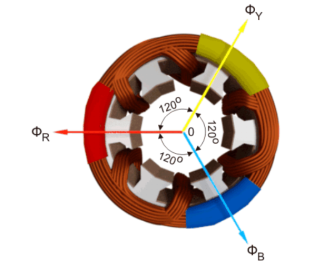
The magnetic flux produced by the current in each phase can be represented by the equations given below. This is a similar representation of current is a three-phase system as the flux is cophasial with the current.
ɸ R = ɸ m sin(wt)
ɸ Y = ɸ m sin(wt -120 0 )
ɸ B = ɸm sin(wt – 240 0 )
Where, φR, φY and φB are the instantaneous flux of corresponding Red, Yellow and Blue phase winding, φm amplitude of the flux wave. The flux wave in the space can be represented as shown below.
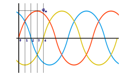
First consider the point 0.
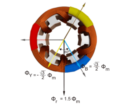
ɸ R = ɸ m sin(0) = 0
The value of
ɸ Y = ɸ m sin(0 – 120 0) = ɸ m sin(-1200) = -  ɸ m
ɸ m
The value of φB is
ɸ B = ɸm sin(0 – 240 0 )= ɸm sin (-240 0 ) =  ɸ m
ɸ m
The resultant of these fluxes at that instant (φr) is 1.5φm which is shown in the figure below.
From the graphical representation of flux waves, consider the point 1, where ωt = π / 6 or 30o.
ɸ R = ɸ m sin(30) = ½ ɸ m
The value of
ɸ Y = ɸ m sin(30 – 120 0) = ɸ m sin (-90) = -ɸm.
The value
ɸ B = ɸm sin(30 – 240 0 ) = ɸ m sin (-210) = ½ ɸ m
The resultant of these fluxes at that instant (φr) is 1.5φm which is shown in the figure below. Here it is clear the resultant flux vector is rotated 30o further clockwise without changing its value.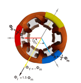
Now, on the graphical representation of flux waves, we will consider the point 2, where ωt = π / 3 or 60o.
ɸ R = ɸ m sin(60) =  ɸ m
ɸ m
The value of
ɸ Y = ɸ m sin(60 – 120 0) = ɸ m sin (-60) = -  ɸm.
ɸm.
The value of
ɸ B = ɸ m sin(60 – 240 0) = ɸ m sin (-180) = 0
The resultant of these fluxes at that instant (φr) is 1.5φm which is shown in the figure below. It shows that the resultant flux vector is rotated 30° further clockwise without changing its value.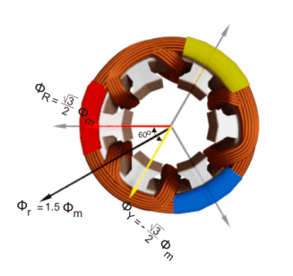
Now, consider the point 3, where ωt = π / 2 or 90o.
ɸ R = ɸ m sin(90) = ɸ m
The value of
ɸ Y = ɸ m sin(90 – 120 0) = ɸ m sin (-30) = -  ɸm.
ɸm.
The value of
ɸ B = ɸ m sin(90 – 240 0) = ɸ m sin (-150) = -1/2 ɸ m.
The resultant of these fluxes at that instant (φr) is 1.5φm which is shown in the figure below. The resultant flux vector is rotated 30o further clockwise without changing its value.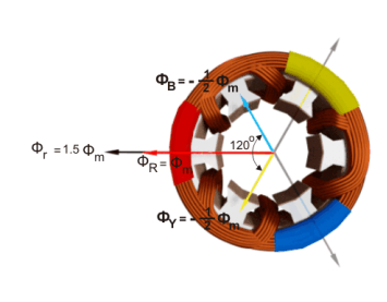
In this way we can prove that the due to balanced supply applied to the three phase stator winding a rotating or revolving magnetic fields is established in the space.
Principle of operation of induction motor:
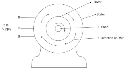
- When the 3Ф A.C supply is connected across the stator of induction motor, the current starts flowing through the stator wdg. i.ethe stator condition.
- Due to this current of flux (Ф) is established in the stator wdg. This flux (Ф) is alternating (changing) in nature. Thus this flux links with the rotor also, and a a Rotating Magnetic Field(RMF) is produced.
- This flux (Ф) induces emf in the rotor also. The RMF is produced in the air gap between stator and rotor.
- The rotor is rotating part which is till stationary, show the rotating magnetic field is cut by stationary rotor and an EMF is induced in the rotor winding. According to faraday's law of EMI the rotor EMF gives the rise to rotor current which opposes the main cause producing it according Lenz's law.
Consider- 3Ф slip ring I.M
Cut section diagram:-
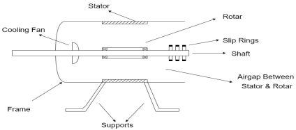
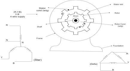
The induction motor has following important parts:-
- Stator :- it is the stationary part of induction motor and it is one of important part in induction motor.
- Rotor:- the rotor is the rotating part of induction motor which consists of rotor wdg.
- Stator winding:- this wdg. Is mounted on devastator and it generates the RMF i.e. rotating magnetic field.
- Rotor winding:- rotor winding is used to rotate the shaft of motor. This wdg is provided on rotor
- Frame :- it provides the mechanical support to the motor. It is the outer covering of motor. It protects the internal parts of motor from damage.
- Shaft:- shaft is used to connect to the load and four rotation.
- Slip rings and brushes:- slip rings are mounted on the shaft which is connected with brushes from which connection is given to the external resistant or rheostat
- Cooling fan:- this is provided for cooling purpose of motor and its internal parts.
Types of induction motor:
Two main types depending upon the rotor
- Squirrel cage induction motor (squirrel cage rotor)
- Slip ring induction motor(slip ring or wound rotor)
Induction motor are also available in 1Ф supply i.e.
1. Resistance split phase induction motor
2. Capacitor start induction motor
3. Capacitor start capacitor run induction motor
4. 1Ф induction motor i.e. A.C series motors
5. Shaded pole induction motor
Torque equation of induction motor:-
Torque produced in induction motor depends upon the following factors
1.The rotor power factors ( CosФ) under running condition
2.The rotor current under running condition
3. The part of RMF which induces EMF in rotor wdgi.e. flux (Ф)
We can mathematically say that,
 , As per DC (M) equation
But in case of induction motor
Suffix 1 -> used for stator/stator parts (qty)
Suffix 2-> used for rotor/rotor parts(qty)
Therefore,  ----(1)
 = flux that induces the EMF in rotor
 = rotor current under running condition
 = P.F of rotor
But, stator vtg
 also i.e
 ----(2)
Transformation ratio i.e. given by 
Therefore,
 and hence
 also
also
 at slip ’S’ is given by
And also  at slip ‘S’ is
  =S.
=S.
Hence  in equation can be replaced by
i.e.  U
U
 =
= ----(3)----(
 )
)
4 =
= ------(4)
Substract (3) and (4) into (1) equation we get,


 (N-m) , Torque equation of I.M.


At starting condition slip S=1
So, 