Unit-2
Equilibrium
Condition of equilibrium for concurrent forces:
- Concurrent means that the forces intersect through a single point.
- If forces are concurrent, we can add them together as vectors to get the resultant.
- If the body is not accelerating, it must be in equilibrium, so that means the resultant is zero.
- For concurrent forces, the body is a point.
- So for concurrent forces in equilibrium, the forces should all add up to give zero.
The sum of all forces in the x-direction or horizontal is zero.
∑Fx =0 or ∑Fy=0
The sum of all forces in the y-direction or vertical is zero.
∑Fy=0 or ∑Fv=0
Important Points for Equilibrium Forces
- Two forces are in equilibrium if they are equal and oppositely directed.
- Three coplanar forces in equilibrium are concurrent.
- Three or more concurrent forces in equilibrium form a close polygon when connected in head-to-tail manner.
Condition of equilibrium for parallel forces:
These are the condition of equilibrium for parallel forces are listed below:
The sum of all the forces is zero.
∑F=0
The sum of moment at any point O is zero.
∑Mo=0
Condition of equilibrium for non-concurrent non-parallel forces:
These are three equilibrium conditions that can be used for non-concurrent non-parallel force system.
The sum of all forces in x-direction or horizontal is zero.
∑Fx =0 or ∑FH=0
The sum of all forces in y-direction or vertical is zero.
∑Fy=0 or ∑Fv=0
The sum of any moment at point O is zero.
∑Mo=0
The three equilibrium conditions can solved up to three unknowns in the system.
Condition of equilibrium for Couple:
A couple can only be put in equilibrium by a moment or another couple of equal magnitude and opposite direction anywhere in the same plane or in a parallel plane. If a single force is added to the system that balances the sum of the moments, one of the other two equations of equilibrium will not be satisfied.
Equilibrium for Rigid Bodies:
For a rigid body to be in equilibrium, the net force as well as the net moment about any arbitrary point O must be equal to zero.
F=0 and M=0
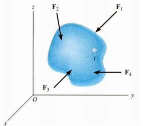
FORCES ON A RIGID BODY
Free Body Diagram:
These are some condition for free body diagram-
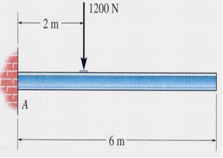
Idealized Model
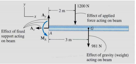
Free-body diagram
- Draw an outlined shape. Imagine the body to be isolated or cut “free” from its constraints and draw its outlined shape.
- Show all the external forces and couple moments. These typically include: a) applied loads, b) the weight of the body, and c) support reactions (can be difficult).
- Label loads and dimensions: All known forces and couple moments should be labeled with their magnitudes and directions. For the unknown forces and couple moments, use letters like Ax, Ay, M A, etc. Indicate any necessary dimensions.
Q1. Draw FBD where one of the blocks is resting on an inclined plane and rope goes over a frictionless massless pulley as shown in figure.
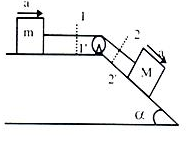
Ans. Here the FBD become.
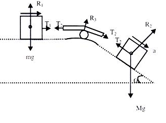
Since, system is fully connected by light inextensible string therefore acceleration in all parts will be equal.
For Block ‘m’
R1-mg = 0
R1= mg
T1= ma ……………………………….I
For Block ‘M’ (Refer to the diagram made with mg cos & mg sin
 component
R2 - mg cos = 0
= 0
R2= mg cos and is parallel to the plane
Mg cos – T2 = Ma……………………..II
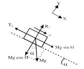
It is already explained that T1 =T2= T
Solving I & II we get “T” and ‘a’ for the system.
Q2. Suppose situation is as shown in figure above that a light inextensible string pulls a block of mass M on a frictionless rigid surface.

Ans. Here the FBD of block
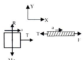
For block
∑Fy = R – mg = 0
R = mg
∑Fx= T = Ma
a = T/m
Beam: - A Beam is an inevitable horizontal or sloping structural element to resist the load of the structure. The main function of the beam is designed to resist the external or internal load such as wall, slab and floors of the building and distribute the load to the foundation through the column.
The horizontal beam carries an only transverse load and the sloping beams carry both transverse and axial load.
Types of beam: There are different types of beam which are listed below.
- Based on geometry:
- Straight beam – Beam with straight profile
- Curved beam – Beam with curved profile
- Tapered beam – Beam with tapered cross section
- Based on the shape of cross section:
- I-beam – Beam with ‘I’ cross section
- T-beam – Beam with ‘T’ cross section
- C-beam – Beam with ‘C’ cross section
2. Based on equilibrium conditions:
- Statically determinate beam – For a statically determinate beam, equilibrium conditions alone can be used to solve reactions.
- Statically indeterminate beam – For a statically indeterminate beam, equilibrium conditions are not enough to solve reactions. Additional deflections are needed to solve reactions.
3. Based on the type of support:
- Simply supported beam
- Cantilever beam
- Overhanging beam
- Continuous beam
- Fixed beam
Classification of beams based on the type of support is discussed in detail below:
- Simply supported beam:-It is one of the simplest structural elements that both ends rest on supports at the other end. Based on the assigned load, it sustains shearing and bending.
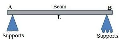
Fig. Simple supported Beam
2. Fixed Beam: - It is supported at both ends and fixed to resist rotation. It is also called a built-in beam. The fixed ends produce moments other than the reactions.
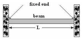
Fig. Fixed Beam
3. Cantilever beam: - If a beam is fixed at one end and set to be free at the other end, it is termed as a cantilever beam. The beam distributes the load back to the support where it is forced against a moment and shear stress. Cantilever beams allow the creation of a bay window, balconies, and some bridges.

Fig. Cantilever Beam
4. Continuous Beam: - A continuous beam has more than two supports distributed along its entire length.
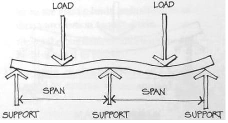
Fig. Continuous Beam
5. Overhanging beam: - An overhanging beam is a beam that has one or both end portions extending beyond its supports. It may have any number of supports. If viewed in a different perspective, it appears as if it is has the features of simply supported beam and cantilever beam.
Q1. Draw shear force diagram for the simply supported beam loaded as shown in figure.

Ans. Let the reaction at support A and B is, RA and RB.


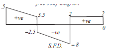
For finding the support reaction to convert UDL in to point load equal to 2*5=10KN, acting at the midpoint of UDL that is 205m from point A.
∑V=0
RA + RB -5.5 -10 -2 =0
RA + RB = 17.5 ………………………….. (1)
Taking moment about point A,
∑MA = 0
10*2.5 + 5.5 * 2 –RB * 5 + 2*7 = 0
RB = 10 KN …………………………………. (2)
From equation (1),
RA = 7.5 KN ………………………………… (3)
Calculation for shear force diagram
Draw section line, here total 3 section line, which break the load RA, 5.5 KN (Between A and E),
5.5KN and UDL (Between E and B),
Point B and 2KN (Between B and C). Let
Distance of section 1-1 from A is X1
Distance of section 2-2 from A is X2
Distance of section 3-3 from A is X3
Take left portion of the beam-
SF1-1 = 7.5 -2X1 KN (Equation of the straight line)
Inclined linear means that the value of shear force at both the nearest point of section varies with X1 = 0 to X1 = 2
To X1 = 2
At X1 = 0
SFA = 7.5 …………………………………….. (4)
At X1 = 2
SFE= 3.5 …………………………………………… (5)
I.e. inclined line 7.5 to 3.5
Consider section 2-2
Force on left of section 2-2 is RA, 5.5 KN and UDL on X2 length
SF2-2 = 7.5 – 5.5 -2 X2 = 2 – 2X2
It is equation of straight line
Inclined linear means value of shear force at the both nearest point of the section is varies with X2 = 2 to X2 = 5
At X2 = 2
SFE = - 2
At X2 =- 5
SFB = -8
That is inclined line -2 to -8
As shear force changes the sign so at any point shear force will be zero and at that point bending moment is highest.
For finding position of zero shear force equate shear force equation to zero, that is,
2 - 2X2; X2 = 1m, that is at 1m from point A bending moment is maximum.
Take section 3-3
SF3-3 = 7.5 - 5.5 -10 +10 = 2KN (constant value)
Constant value means that the value of shear force at both nearest point of the section is equal that is
SFB =SFC =2KN
Plot the SFD with the help of obtained shear force values.
Q 2. Cantilever beam with point load at the free end.
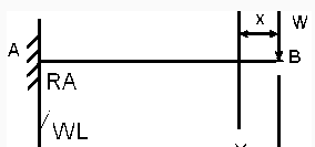
Ans. In cantilever beam we start from free end let us considered X-X section at a distance of x from free end.
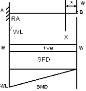
Reaction Ra is given by the height S.F.D
Shear force at X-X
S.Fxx = W
Moment at X-X
MX-X = - Wx
At B,
X = 0, (S.F)B = W
MB = 0, (S.F)A = W , MA = - WL
Q3. Cantilever beam is subjected to the moment at the free end.

Ans. To find the condition of beam
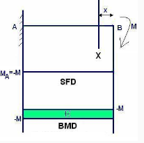
MX=-M
MB=-M
(S.F)X-X=0
At B,
MB=-M
SFB=0, SFA=0
Whenever there is point load acting there is a sudden change in S.F.D. Similarly whenever a concentrated moment is acting there is a sudden change is S.F.D. In presence of point load there is a sudden change in S.F.D at that corresponding point. .In presence of concentrated moment there is a sudden change in B.M.D at that corresponding point.
Types of Supports and Reaction: - Support in a structure is a member which helps others member to resist loads. Different types of supports, their reactions are discussed below.
Supports in a structure transfer the load to the ground and provides stability to the structure supported on it.
Supports can be mainly classified into two ways.
External Supports
Internal Supports
External supports and reaction: - The supports which are usually provided externally without disturbing the structural member are external supports. Different types of external support are as follows.
- Fixed support
- Pinned support or hinged support
- Roller support
- Rocker support
- Link support
- Simple support
Fixed support and reaction: - Fixed supports are also called as rigid supports. Fixed supports are restrained against both rotation and translations they can resist any type of force or moment.
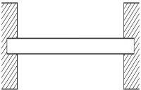

Fig. Fixed Support and Reaction
Pinned support or hinged support: - Pinned support can resists both vertical and horizontal forces but they cannot resist moment. It means hinged support is restrained against translation. The rotation of pinned support or hinged support is allowed in only one direction and is resisted in other direction.


Fig. Pinned Support and Reaction
Roller support and Reaction: - Roller supports only resist perpendicular forces and they cannot resist parallel or horizontal forces and moment. It means, the roller support will move freely along the surface without resisting horizontal force.


Fig. Roller support and Reaction
Internal support and Reaction: - Internal supports are provided internally in the structure member which means an internal support divided the full member into parts. So, the external reaction can be found for each part which will be quite easier for the analysis.
Following are the types of internal supports provided in a structure:
- Internal Hinge
- Internal Roller
Internal Hinge: - Similar to hinge support internal hinge also resists translation in both directions and allows only rotation.
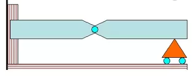
Fig. Internal Hinge
Internal Roller: - Internal roller supports are same as roller supports but they are provided in the middle of structural member.
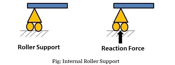
This type of internal roller supports are used in tower cranes or harbor cranes so, using the horizontal movement of support heavy materials or members can be shifted from one place to another place.
Determine of reaction at supports for various types of load on beams:
Since a simply supported beam is a determinate structure, it is possible to obtain its static response using just equilibrium equations. These equations enforce that the sum of all forces and moments, acting upon the structure, in any direction, including both applied loads and support reactions, must be zero. For a plane structure, with in plane loading, the equilibrium equations are:
∑Fx =0
∑Fy=0
∑Many point =0
The first two equations, enforce force equilibrium in directions x and y, (a Cartesian system of axes that can be arbitrarily defined, depending on the case). The third equation enforces the equilibrium of all moments around a certain point, which can be any point of the plane.
Support reaction of a simply supported beam with a point load-
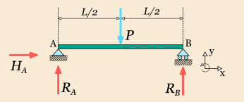
Assigning the unknown support reaction to variables RA, HA and RB, as shown in figure, the three equilibrium equations are defined this way.
- Along direction x, there is no imposed force applied to the structure. There is only the unknown support reaction HA. Thus the first equilibrium equation is;
∑Fx =0 or H=0
- Along direction y, the imposed force P is applied to the center of the beam, as well as support reaction RA and RB. Thus the first equilibrium equation is:
∑Fy=0
RA + RB –P = 0
- For the third equation we have to choose one point around which the moments are calculated. It is often more convenient to select a point through which some of the forces are directed (such as point A in our examples), because, the resulting moments for these forced would be zero. So, around point A, support reaction HA and RA have no lever arm, imposed force P have a lever arm equal to half the beam length and support reaction have a lever arm equal to half the beam length and support reaction have a lever arm equal to the beam length. Assuming counter-clockwise positive rotation, the third equation becomes.
∑M=o
HA * 0 + RA * 0 - P + RB L= 0
There are three unknowns, and we have three equations, therefore it is possible to solve the system of equation and obtain the unknown support reaction. HA is directly found from the first equation to zero. Unless there is an imposed load along the beam longitudinal axis, this reaction will always be zero. From the third equation we can directly obtain. RB
- P + RB L= 0
RB= P
And finally substituting the values of reaction and found too-
RA – P = 0
= 0
RA = 
Support reactions of a simply supported beam with distributed load:-

Before proceeding to the equilibrium equations, we will replace the distributed load with an equivalent point force W. This force should have the same downward direction and a magnitude equal to the total load, that is W= wL/2. Its application point should be located at the centroid of the distributed load it replaces, in this case one quarter length from the right end of the beam. The following figure illustrates the beam, with the equivalent load we are going to use, for the needs of equilibrium.
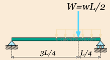
Next we assign the unknown support reaction to variables RA, RB and HA .we define the x, y axis as shown in figure below.
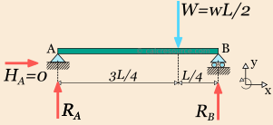
Because there is no horizontal component of imposed load, reaction HA should be zero, by virtue of the equilibrium equation ∑Fx=0. The remaining two non-trivial equation, are written below, taken into account the positive direction, indicated by our axis system.
∑Fy= 0
RA + RB -  = 0
= 0
∑M=0
RA * 0 -  + RB L = 0
From the last equation we can find RB-
 + RB L = 0
RB = 
Substituting the value of reaction in equation and find out the other reaction value-
RA +  -
-  = 0
= 0
RA -  = 0
= 0
RA = 
Q1. A simply supported beam AB of span 5 m is loaded as shown in fig. Find the reaction at A and B.

Ans. Given that
(l) = 5m
Let RA and RB reaction at point A and B
We know that anticlockwise moment due to RB about A
= RB * l = RB*5 = 5RB KN.M
And sum of the clockwise moment about A,
= (3*2) + (5*4) =38 KN.M
We know that clockwise moment and anticlockwise moment are equal
5 RB = 38 or RB = 7.6 KN
RA = (3+43+5) – 7.6 = 4.4 KN
Q2. A simply supported beam, AB of span 6 m is loaded as shown in Fig.
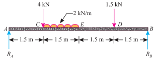
Ans. Given: Span (l) = 6m
Let RF and RB at reaction of a point A and B. We know that anticlockwise moment due to reaction RB about A.
= RB × l = RB × 6 = 6 RB KN-m ……………….. (i)
And sum of clockwise moment about A.
= (4 × 1.5) + (2 × 1.5) 2.25 + (1.5 × 4.5) = 19.5 KN-m ….. (ii)
Equating anticlockwise and clockwise moments given in (i) and (ii),
6 RB = 19.5
RB = 3.25 KN
RA = 4 + (2*1.5) + 1.5 – 3.25 = 5.25 KN
Q3. A beam AB 5 m long supported on two intermediate supports 3 m apart carries a uniformly distributed load of 0.6 KN/m. The beam also carries two concentrated loads of 3 KN at left hand end A, and 5 KN at the right hand end B as shown in Fig.
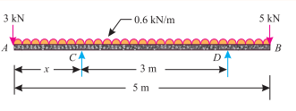
Ans. Given: Length of the beam AB (L) = 5 m and span (l) = 3 m.
Let RC and RD reaction at point C and D, X distance of support C form left hand side,
We know that total load on the beam
=3 + (0.6 * 5) + 5 = 11 KN
Since reaction RC and RD are equal, therefore reaction at support
=  = 5.5 KN
We know that anticlockwise moment due to RC and RD about A
= 5.5 × x + 5.5 (x + 3) = 5.5 x + 5.5 x + 16.5 KN-m
= 11x + 16.5 KN-m ... (i)
And sum of clockwise moment due to load about A,
= (0.6 × 5) 2.5 + 5 × 5 = 32.5 KN-m ... (ii)
Now equating anticlockwise and clockwise moments given in (i) and (ii)
11 x + 16.5 = 32.5 or 11 x = 16
X= 1.45m
It is thus obvious that the first support will be located at distance of 1.45m from A and second support at a distance of 1.45 + 3 = 4.45 m from A.
Video link: - https://youtu.be/wZdqtXp-trg
Book reference:-
- Meriam J.L and kraige L.G. Engineering Mechanics
- Kumar, K.L. Engineering Mechanics
- Bhavikatti, S.S, and Rajashekarappas. K.G. Engineering Mechanics