UNIT 5
Kinematics of Rigid Body
A rigid body is an ideal body that does not change its shape when subjected to external forces or couples. The distance between the particles in a rigid body remains same during the motion. Hence, a rigid body can be defined as the group or collection of number of particles at fixed distance from each other.
There are three types of motion of a rigid body
- Translation
- Rotation
- General Plane Motion
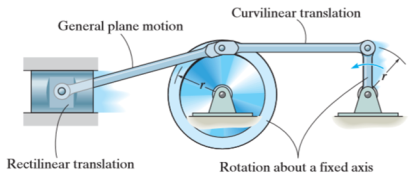
Kinematics of rigid body in translation motion
Translation motion occurs when a line (generally axis) in the body remains parallel to its initial orientation throughout the motion.
If the path of motion of any two lines on the rigid body is parallel or is in a straight line, then the translation is termed as rectilinear translation.
If the path of motion of any two lines on the rigid body is along the fixed curve, then the translation is termed as curvilinear translation.
Consider a rigid body that is subjected to translation motion as shown in fig.
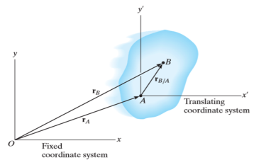
The position of points A and B is defined are defined by the position vectors  and
and  w.r.t the fixed frame x, y.
Let the translating system is fixed in a body with origin A which is referred to the base point. The position vector of B w.r.t A is denoted by  .
.
By vector addition, we get,


Taking, the first time derivative of the above equation, we get,

According to the definition of rigid body, the term  is constant
Hence,

And,  gives the absolute velocities
  and
and  respectively with respect to the fixed frame.
So, we get,

This shows that, for the rigid body in translation motion, the velocity of every particle on the body is same.
Now, taking the time derivative of the velocity equation, it simply yields

Where,  and
and  are the absolute accelerations of points A and B on the rigid body w.r.t fixed frame.
This shows that, for the rigid body in translation motion, the velocity and acceleration of every particle on the body is same.
Kinematics of a body rotating about fixed axis
When a rigid body is subjected to the rotation about a fixed axis, as shown in fig below, all the particles of the body, except those which lie on the axis of rotation, move along circular paths whose center lies on the axis of rotation.
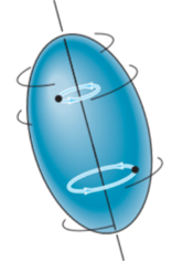
Consider, the point P on the rigid body defined by the position vector r. As the rigid body rotates about the fixed axis, then the point P travels a circular path of radius r with center point O as shown in fig below
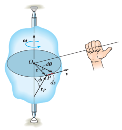
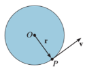
If the body rotates with a differential angular displacement , then the point P displaces the distance
  , which is given by

Differentiating the above equation w.r.t time, we get

The term,  is referred to as the angular velocity
  of the rotating body
And  gives the velocity of point P
Hence,

The direction of velocity is tangent to the circular path.
Considering the magnitude and direction, velocity is the cross product of angular velocity and the position vector

Where,  is directed from axis to the point P
To find acceleration, differentiate velocity vector w.r.t time

Here, the term  refers to the angular acceleration
  of the rigid body
And  is the velocity
Hence,


Where,  is the tangential acceleration and
  is normal component of acceleration
Hence,

Magnitude of both components is given by,


Tangential component refers to the time rate of change of velocity’s magnitude. Hence, if velocity of point P is increasing,  is in same direction of
  , but if velocity of point P is decreasing,
  is in direction opposite to that of
The normal component of acceleration refers to time rate of change of the velocity’s direction. Hence, the direction of the normal component is always from point P towards the center O. Hence it is also called as centripetal acceleration.

General Plane motion
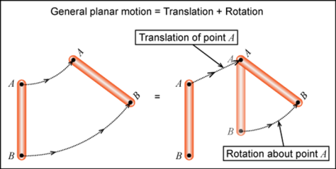
General plane motion of a rigid body refers to a combination of translation and rotation motion.
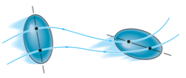
General planar motion refers to the simultaneous rotational and translational motion of a planar body in a 2-D plane.
General planar motion can be fully specified by knowing both the angular rotation of a line fixed in the body and the motion of any point on the body.
These motions can be related by using a rectilinear position coordinate s to locate the point along its path and an angular position coordinate  to specify the orientation of the line. Then these two coordinates are related using the geometry of the problem. The following relation is found.

Differentiating the above equation, gives the relation between velocity  and angular velocity
  .
.
Where,

Then again differentiating, it yields to the relation between acceleration  and angular acceleration
Where,


Instantaneous Center of Velocity (ICV):
Any point on a rigid body or on its extension that has zero velocity is called the Instantaneous Center of Velocity of the body. Assuming one knows the ICV of a body, one can calculate the velocity of any point A on the body using the equation
VA=VA/ICV + VICV and recognizing that be definition
VICV = 0. This gives
VA= ω x rA/ICV
|
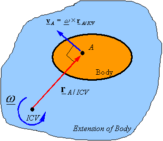
In 2-D motion, if rA/ICVis in the plane of motion and ω is perpendicular to this plane, then one can use the scalar relation

Methods of finding the ICV:
|
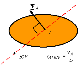
Given the velocity VA of point A on a rigid body and the angular velocity of the rigid body one can use the above equation to find the distance rA/ICVbetween the point A and the ICV. One can then draw a line perpendicular to the velocity and passing through A, and move along this line a distance rA/ICV to get to the ICV. The side on which the ICV is can be determined by the direction of the angular velocity.
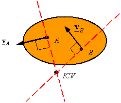
Given the velocity of points A and B on a rigid body one can find the ICV by drawing a line perpendicular to VAand passing through A, and by drawing a line perpendicular to VBand passing through B. One of the following three cases will result
The lines intersect at one point: The point of intersection is the ICV. The angular velocity can be calculated once the ICV is determined using the velocity of both point and its corresponding distance from the ICV.
|
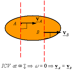
The lines are parallel (they intersect at infinity): The ICV is at infinity, and the angular velocity is zero since infinity times zero is the only way one can get velocities other than infinite. Therefore, the body is in pure translation and the velocity of the two points must be the same.
|
The two lines fall on top of each other: One can find the location of the ICV using the proportionality of velocity and distance from the ICV to create similar triangles. This follows from
|
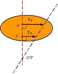

ω = VA / rA/ICV = VB/rB/ICV
We know that the motion of a wheel is a combination of translational as well as rotational motion. So instantaneous centre of rotation (ICOR) is the point from where the motion can be analyzed as a pure rotational motion.
Concept of ICOR.
Let’s take an example of a wheel. If we assume that the wheel is in pure rolling then the lowermost point has zero velocity. So if we analyze the motion from that point at that instant then the wheel will have a pure rotational motion about that point.
How can we locate the instantaneous centre of rotation?
We can have following different situations:
Case I: When two arbitrary velocities are given:
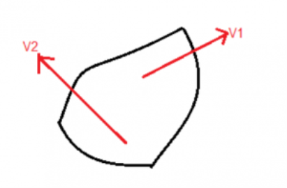
We will draw a perpendicular from the two velocities, the point where they intersect is the ICOR.
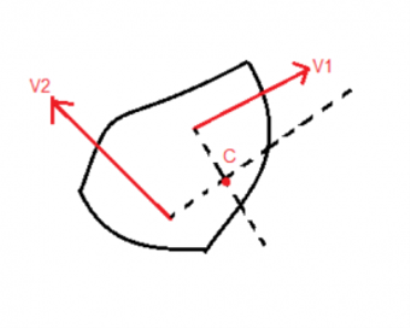
Case II: When two Parallel velocities are given as shown:
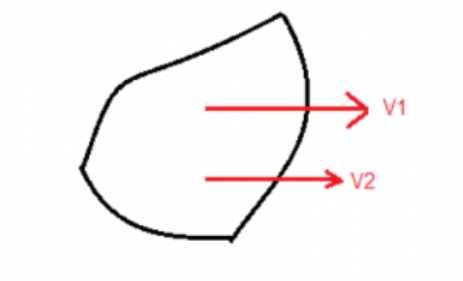
Draw two perpendicular lines from the tails of the velocity vectors. Now draw a line joining their heads which intersects the perpendicular line. That point of intersection is the ICOR.
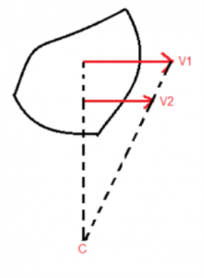
Here point C is the Instantaneous centre of rotation.
Illustrate: the importance of ICOR?
Let’s take a rod that is kept on a frictionless floor a slight impulse is given such that it starts rotating while falling down. We have to find the velocity of the center of mass.
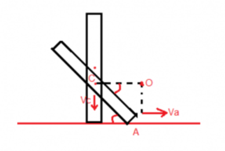
Since there is no frictional force hence there is no force in the horizontal direction, so the centre of mass will only have a vertical velocity say Vc. Also, the lowermost point will only have a horizontal velocity. Let it be Va. First, we will find the ICOR drawing lines perpendicular to the velocity vectors. They intersect at O. So the whole body will seem to be in the pure rotation from that point. Let the angular velocity be Va. Now the centre of mass has come down by
1/2(1–sinθ).
By energy conservation,
Mg ½(1−sinθ)=1/2 IICOR ω2——- (1)
By parallel axis theorem,
IICOR = ml2/12 =ml2cos2θ/4 ——- (2)
Using (1) and (2), we can find the value of ω.
Once it is known we can find,
Vc =ω×1/2 cosθ
Location of Instantaneous Centers
1. When the two links are connected by a pin joint, the instantaneous center lies on the center of the pin
2. When the two links have a pure rolling contact, the instantaneous point lies on their point of contact
3. When the two points have a sliding contact, the instantaneous center lies on the common normal at the point of contact (the members must have the same component of velocity in the direction normal to the sliding surface).
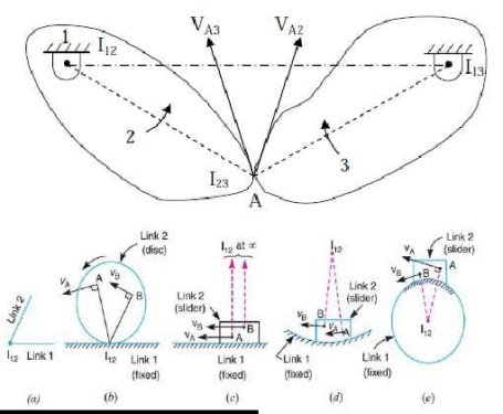
“Point on a rigid body whose velocity is zero at a given instant” Instantaneous: May only has zero velocity at the instant under consideration. Idea: If we know the location of an instant center in 2D motion and we know the angular velocity of the rigid body, the velocities of all other points are easy to determine. Figure 1: Rigid body where I is the instant center. Figure by MIT OCW. vA = vI + ω× rIA = 0 + ω× rIA (1) vA = ω× rIA So body is undergoing rigid body rotation about I. How to locate an instant center?
1. Draw lines in direction of motion of two points on a rigid body.
2. Draw perpendiculars to both these lines at points
3. I is the intersection of perpendiculars.
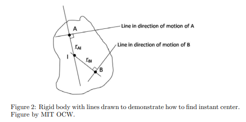
vI = vA + ω× rAI (ω is angular velocity of rigid body.) ω× rAI : Vector is ⊥ to rAI . Direction of motion is parallel to motion of A. vI = vB + ω× rBI ω× rBI:
Vector is ⊥ to rBI. Direction of motion is parallel to motion of B. Cannot satisfy both of these unless vI = 0. (I is the instant center.) Note: The instant center may not actually be a point on the rigid body. This simply means that the body is instantaneously rotating about an external point. The instant center can change in time.
The properties of the instantaneous centre are given below:
1. A rigid link rotates instantaneously relative to another link at the instantaneous centre for the configuration of the mechanism considered.
2. The two rigid links have no linear velocity relative to each other at the instantaneous centre. At this point (i.e. instantaneous centre), the two rigid links have the same linear velocity relative to the third rigid link. In other words, the velocity of the instantaneous centre relative to any third rigid link will be same whether the instantaneous centre is regarded as a point on the first rigid link or on the second rigid link.
3 Velocity of any point on a link with respect to another point (relative velocity) on the same link is always perpendicular to the line joining these points on the configuration (or space) diagram.