Unit 4
INTERFERENCE IN THIN FILM
In this method, the amplitude of the incident beam is divided into two or more parts either by partial reflection or refraction. Thus, we have coherent beams produced by division of amplitude. These beams travel different paths and are finally brought together to produce interference. The effects resulting from the superposition of two beams are referred to as two beam interference and those resulting from superposition of more than two beams are referred to as multiple beam interference. The interference in thin films, Newton's rings, and Michelson's interferometer are examples of two beam interference and Fabry-Perot's interferometer is an example of multiple beam interference.
Let S be a narrow slit illuminated by monochromatic light of wavelength? and S 1 and S 2 be the two narrow slits separated by a small distance 2 d (as in Figure 5). Let a screen XY be placed at a distance D from the coherent sources S 1 and S 2. Let O be the foot of the perpendicular drawn from C, the midpoint of S 1 and S 2 on the screen. Now consider a point P on the screen at a distance x from O at which the condition for bright and dark fringes are to be determined. Draw S 1M and S 2N perpendiculars from S 1 and S 2 on the screen and join S 1P and S 2P. The path difference between the waves reaching at P from S 1 and S 2 is given by

In a right-angled triangle S 2NP, we have

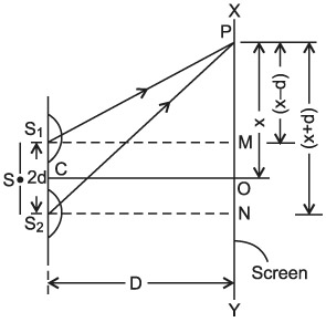
Using the binomial theorem and neglecting higher terms, since D >> x or d, we get
(1) |  |
Similarly, in a right-angled triangle S 1MP, we have
(2) | 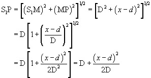 |
Path difference, 

(3) |  |
If the sources S 1 and S 2 are in the same phase as the waves reaching at P, the path differences must only be due to path difference
4.1.1Interference in thin film of constant thickness due to reflected and transmitted light:
A film of thickness from 0.5 to 10  m is a transparent medium of glass, mica, air enclosed between glass, soap film, etc. When the light is made incident on this thin film partial reflection and partial refraction occur from the top surface of the film. The refracted beam travels in the medium and again suffers partial reflection and partial refraction at the bottom surface of the film. In this way several reflected and refracted rays are produces by a single incident ray. As they move are superimposed on each other and produces interference pattern.
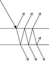
Interference in Parallel Film (Reflected Rays)
Consider a thin film of uniform thickness ‘t’ and refractive index  bounded between air. Let us consider monochromatic ray AB is made incident on the film, at B part of ray is reflected (R1) and a part is refracted along BC. At C The beam BC again suffer partial reflection and partial refraction, the reflected beam CD moves again suffer partial reflection and partial refraction at D. The refracted beam R2 moves in air. These two reflected rays R1 and R2 interfere to produce interference pattern.

The optical path difference between the two reflected rays

In ΔBDN, sin i = BN / BD and BC = CD as ΔBMC ≡ΔMCD, therefore

In ΔBMC, cos r = t /BC, therefore


In ΔBMC, tan r = BM / t , therefore

According to snell’s law 


Correction on account of phase change at reflection:
When a beam is reflected from a denser medium (ray R1 at B), a path change of  /2 occur for the ray.
Therefore, the true path difference is 
Condition of Maxima (Bright Fringe)
Maxima occur when path difference


 ..
..
Condition for Minima (Dark Fringe)
Minima occur when path difference


Interference in Parallel Film (Transmitted Rays)
The optical path difference between transmitted rays T1 and T2 will be
This path difference is calculated in the same way as above to get
 .
.
Condition of Maxima (Bright Fringe)
Maxima occur when path difference,

 .....
.....
Condition for Minima (Dark Fringe)
Minima occur when path difference,


4.1.2 Origin of colours in thin film:
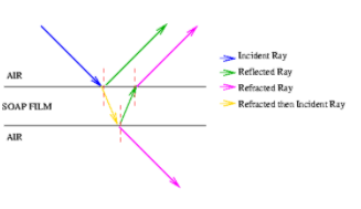
Everyone is familiar with the brilliant colours exhibited by a thin oil film spread on the surface of water and also by a soap bubble. These colours are due to interference between light waves reflected from the top and the bottom surfaces of thin films. When white light is incident on a thin film, the film appears coloured and the colour depends upon the thickness of the film and also the angle of incidence of the light.
4.1.3 Wedge shaped film:
Interference in Wedge Shaped Film (Reflected Rays)
The wedge-shaped film has a thin film of varying thickness, having thickness zero at one end and increases at the other. The angle of wedge is  .
.
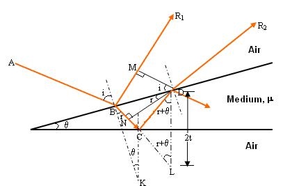
The optical path difference between the two reflected rays R1 and R2 will be

From the geometry

As in ΔBMD;

And in ΔBND

According Snell’s Law,

Or 
Thus 


As in ΔNDL

Correction on account of phase change at reflection: when a beam is reflected from a denser medium (ray R1 at B), a path change of  /2 occur for the ray.
There-fore the true path difference is

Condition of Maxima (Bright Fringe)
Maxima occur when path difference,


Condition for Minima (Dark Fringe)
Minima occur when path difference


4.1.4 Newton ‘s rings:
NEWTON'S RINGS are the circular interference pattern first discovered by Newton.
Formation of fringes
When a plano-convex lens with large radius of curvature is placed on a plane glass plate such that its curved surface faces the glass plate, a wedge air film (of gradually increasing thickness) is formed between the lens and the glass plate. The thickness of the air film is zero at the point of contact and gradually increases away from the point of contact.
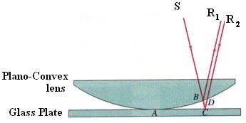
If monochromatic light is allowed to fall normally on the lens from a source 'S', then two reflected rays R1 (reflected from upper surface of the film) and R2 (reflected from lower surface of the air film) interfere to produce circular interference pattern. This interference pattern has concentric alternate bright and dark rings around the point of contact.
Theory of Fringes:
The effective path difference between the two reflected rays R1 and R2 for a wedge-shaped film

If the light is incident normally on the lens, r = 0 and near to point of contact  is small; there-fore near point of contact,
Therefore 
At point of contact t = 0 therefore the effective path difference ∆ = λ/2 which is odd multiple of λ/2 There-fore the Central fringe is dark.
Condition of Maxima (Bright Fringe): The effective path difference  ; substituting this


Condition for Minima (Dark Fringe): The effective path difference ; substituting this in equation

 …
…
From above it is clear that for particular dark or bright fringe t should be constant.
Every fringe is the locus of points having equal thickness. Hence the fringes are circular in shape.
Diameter of Newton’s Rings:
To calculate the diameter of fringes, assume a plano-convex lens is placed on a plane glass plate as shown in figure say R be the radius of curvature of lens. In ΔO’ML
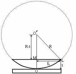


As t << R; neglecting t2 (small value)


Diameter of Dark Rings
Substitute this


As Dn = 2rn


The medium enclosed between the lens and glass plate is if air therefore,  = 1. The diameter of nth order dark fringe will be
 ….
….
 ; n = 0, 1, 2, 3, 4….
The diameter of dark ring is proportional to square root of natural numbers
Diameter of Bright Rings
Substitute t above:


As Dn = 2rn


The medium enclosed between the lens and glass plate is if air therefore, = 1. The diameter of nth order bright fringe will be
 …..
…..
 ; n = 0, 1, 2, 3, 4….
The diameter of bright ring is proportional to square root of odd natural numbers
Spacing between Fringes
The Newton’s rings are not equally spaced because the diameter of ring does not increase in the same proportion as the order of ring and rings get closer and closer as ‘n’ increases.
For example the diameter of dark ring is given by
Where n = 0, 1, 2, 3, 4….


From above, we conclude that the fringe width reduces with increase in ‘n’.
Newton’s Ring with White Light
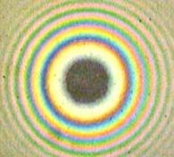
If the monochromatic source is replaced by the white light few coloured rings are seen around dark centre later illumination is seen in the field of view.
4.2.1Determination of thickness of very thin wire or foil:
DIAMETER OF A THIN WIRE:
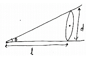
Take two optically flat glass plates and held them together at one end so that a wedge-shaped air film is formed with a very small wedge angle ѳ. At other end put the wire or foil whose diameter is to be determined. From the figure, tan ѳ = d/l……………………. (1)
Also, tan ѳ =λ/2μꞵ……………. (2)
From 1 &2
d/l = λ / 2μꞵi.e. d = lλ / 2ꞵ
For an air film μ =1, which is distance between two dark or bright/dark bands can be measured experimentally. Therefore, diameter can be determined.
4.2.2 Determination of Wavelength of incident Light
In order to determine the wavelength of monochromatic source an experimental arrangement is set up as shown in figure.
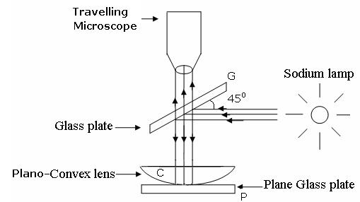
The monochromatic light is made incident on the plano-convex lens and the reflected light is viewed in travelling microscope. Microscope is adjusted till the circular rings came in focus. Now the microscope crosswire is focused on the central dark spot and is moved slowly at one side, say right side. As the cross – wire moves in the field of view, dark rings are counted. The movement is stopped when it reaches at the 22nd dark ring. The cross wire is moved in opposite side and stopped at 20th dark ring such that the vertical cross-wire is made tangential to the ring. Thus, starting from 20th, the microscope position is noted down for 18th, 16th, 14th, …...6th ring. The microscope is quickly moved to the left side of the ring pattern and the positions of microscope is again noted down for 6th, 8th, 10th,20th ring. The diameter of the nth order ring is calculated by subtracting the left and right-side position of the microscope. As we know that the square of diameter of nth dark ring is

There-fore the square of diameter of (n+p) th ring is

Subtracting both the above equation ..
..
Therefore
 .
.
4.2.3 Determination of Refractive Index of liquid
In order to determine the refractive index of liquid the Newton’s ring experiment is first performed for the air medium and the difference in the square of the diameter of (n+p) th and nth dark ring is found as discussed above.

After this few drop of liquid of  refractive index is placed on the glass plate. The plano-convex lens is then placed on the glass plate, as a result a film of liquid is formed between the lens and the plate.
The difference in the square of the diameter of (n+p)th and nth dark ring is again calculated in the same manner for the liquid medium.

Dividing equation , we get

4.2.4 Radius of curvature of lens:
This method involves the measurement of radius of a clearly visible dark fringe preferable away from the centre. By knowing the fringe number, the thickness of the air film which creates the path difference causing the destructive interference leading to the formation of that dark fringe is calculated. Radius of curvature is obtained from the formula which is easily derived from trigonometrical relationships. It is assumed that the radius of curvature is large in comparison with the path difference.
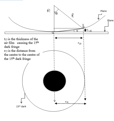
From the figure

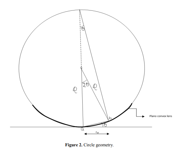
From trigonometry, assuming ab to be very small,
So

Where R is the radius of curvature of the Plano convex lens
4.2.5 Testing of surface flatness:
If an optical flat is placed upon another flat reflecting surface (without pressure) it willnot form an intimate contact, but will lie at some angle 0 making an inclined plane. If theoptical flat be now illuminated by monochromatic source of light, the eye if placed in properposition, will observe a number of bands. These are produced by the interference of the light
rays reflected from the lower surface of the top flat and the top surface of the lower flat throughthe very thin layer of air between the flats. The angles 6 between the two flats isshown exaggerated too much. S is the source of monochromatic light. At point A, the wave of
incident beam from S is partially reflected along AB and is partially transmitted across the
air gap along AC. At C, again the ray is reflected along CD and passes out towards the eye
along CDE. Thus, the two reflected components, reflected at A and C are collected and
recombined by the eye, having travelled paths whose lengths differ by an amount ACD.
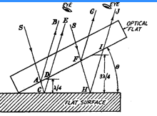
If the path lengths of the two components differ by an odd number of half wavelengths,
then condition for complete interference is achieved. If the surface is perfectly flat, thencondition of complete interference is satisfied in a straight line across the surface as the surfaceat right-angles to the plane of the paper is parallel to the optical flat. Therefore, a straightdark line will be seen passing through point C. Consider another ray incident along path SFH.Again, this ray is also spilatted into two components. It is obvious that the path difference of thetwo component rays will keep on increasing along the surface due to angle 9.
Thus, if the pathdifference FHI be 3X12 or the next odd number of half wavelengths, then interference will occurand a similar fringe will be seen. Next when path difference is 5K/2, again there will be anotherdark fringe. At the intermediate point between the points C and H, the path difference will be an even number of half wavelengths and the two components will be in phase producing a lightband.
Thus, in case of a perfectly flat surface, we will have pattern of alternate light and darkstraight lines on the surface. Any deviation from this pattern will be a
measure of the error in the flatness of the surface being inspected.
4.2.6 Anti-reflecting films and Highly reflecting film:
The cancellation (destructive interference) of reflected light waves is utilized to make non-reflective coatings. Such coatings are commonly found on some camera lenses or binocular lenses, and often have a bluish tint. The coating is put over glass, and the coating material generally has an index of refraction less than that of glass. In that case, then, both reflected waves have a 180° phase shift, and a film thickness of 1/4 wavelength (in the film) would produce a net shift of 1/2 wavelength, resulting in cancellation.
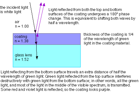
For non-reflective coatings, then, the minimum film thickness required is:

Where n is the index of refraction of the coating material.
Note that you have to be very careful to account for whether a phase shift occurs at an interface where reflection is taking place. In some cases, the minimum film thickness required for constructive interference is a quarter of the wavelength; in other cases, the minimum film thickness must be half a wavelength for constructive interference to take place. It all depends on whether or not a phase shift occurs for reflections at both interfaces, one interface, or neither interface.