Unit - 4
Polarization of Electromagnetic Waves
4.1.1 Polarization of Electromagnetic Waves
The electric component of an electromagnetic plane wave can oscillate in any direction normal to the direction of wave propagation (which is parallel to the  vector) (Fitzpatrick 2008). Suppose that the wave is propagating in the
  -direction. It follows that the electric field can oscillate in any direction that lies in the
  plane. The actual direction of oscillation determines the polarization of the wave. For instance, a vacuum electromagnetic wave of angular frequency
  that is polarized in the
  -direction has the associated electric field
 (564)
(564)
Where  . Likewise, a wave polarized in the
  -direction has the electric field
 (565)
(565)
Because the electric field vector oscillates in a straight line, these two waves are referred to as linearly polarized. Other types of polarization, on the other hand, are feasible. For example, if two linearly polarized waves of equal amplitude are combined, one polarized in the  -direction, and one in the
  -direction, that oscillate
  radians out of phase, then we obtain a circularly polarized wave:
 (566)
(566)
The fact that the tip of the electric field vector traces out a circle in the plane corresponding to the direction of wave propagation gives birth to this nomenclature. To be more precise, the previous wave is a right-hand circularly polarized wave, because the electric field vector rotates in the same way as the fingers of this hand when the thumb of the right-hand points in the direction of wave propagation. A left-handed circularly polarized wave, on the other hand, assumes the form
 (567)
(567)
Finally, if the  - and
- and  When the amplitudes of the electric field components in the above two formulas differ, we get right-hand and left-hand elliptically polarized waves, respectively. The fact that the tip of the electric field vector traces out an ellipse in the plane corresponding to the direction of wave propagation gives birth to this nomenclature.
4.1.2 Linear polarization
The restriction of the electric field vector or magnetic field vector to a specified plane along the propagation direction is known as linear polarization or plane polarization in electrodynamics. For more information, see polarization and polarization plane.
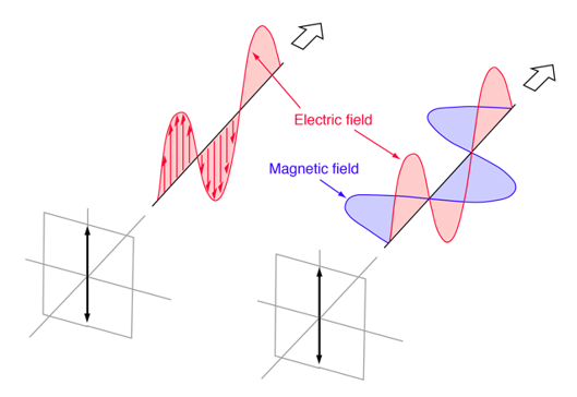
The direction of the electric field vector determines the orientation of a linearly polarized electromagnetic wave.
1st The radiation is considered to be vertically polarized if the electric field vector is vertical (alternating up and down as the wave travels).
A linearly polarized electromagnetic wave is one that travels in a plane. As seen, a magnetic field wave accompanies the transverse electric field wave.
4.2.1 Circular Polarization
Two perpendicular electromagnetic plane waves of equal amplitude and phase difference of 90 degrees make up circularly polarized light. Right-circularly polarized light is depicted in this illustration.
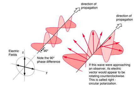
Light is considered to be circularly polarized if it is made up of two plane waves of identical amplitude but 90° phase difference. If you could see the tip of the electric field vector approaching you, it would appear to be travelling in a circle. The light is said to be right-circularly polarized if the electric vector of the light travelling toward you appears to be rotating counterclockwise while staring at the source. Left-circularly polarized light if clockwise. As the light moves one wavelength closer to you, the electric field vector completes a full rotation. Another way to put it is that if your right hand's thumb were pointed in the direction of light propagation, the electric vector would rotate in the direction of your fingers.
By passing linearly polarized light through a quarter-wave plate at a 45° angle to the plate's optic axis, circularly polarized light can be created.
4.2.2 Elliptical Polarization
Elliptically polarized light is made up of two perpendicular waves of unequal amplitude that are 90 degrees out of phase. Right-elliptically polarized light is depicted in the figure.
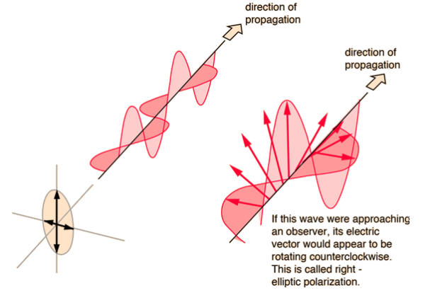
The electric vector would rotate in the direction of your fingers if your right hand's thumb was pointing in the direction of light propagation.
4.3.1 What are Uniaxial Crystals?
A uniaxial crystal is an optical element that has a single optic axis. In other words, a uniaxial crystal has one crystal axis different from other two crystallographic axes. Ex: na=nb≠ nc. An unusual axis is the name given to this one-of-a-kind axis. A light beam divides into two parts when it passes through a uniaxial crystal, such as the ordinary ray and remarkable ray. The ordinary ray (o-ray) does not deviate as it goes through the crystal. At the air-crystal interface, the extraordinary ray (e-ray) deviates.
Negative uniaxial crystals and positive uniaxial crystals are the two types of uniaxial crystals. It is a negative uniaxial crystal if the refraction index of the o-ray (no) is greater than that of the e-ray (ne). It is a positive uniaxial crystal if the e-ray refraction index (ne) is less than that of the e-ray. (The refractive index is a measure of how well something reflects light.)
The ratio of the velocity of light in a vacuum to its velocity in the crystal). Examples of negative uniaxial crystals include calcite (CaCO3), ruby (Al2O3), etc. Examples of positive uniaxial crystals include quartz (SiO2), sellaite (MgF2), rutile (TiO2), etc.
4.3.2 What are Biaxial Crystals?
An optical element with two optic axes is known as a biaxial crystal. A light beam divides into two fractions when it passes through a biaxial crystal, both of which are exceptional waves (two e-rays). These waves travel in a variety of directions and at varying speeds. Biaxial crystal systems include orthorhombic, monoclinic, and triclinic crystalline forms.
The following are the Refractive Indices for a Biaxial Crystal:
1. The refractive index with the least value is (the corresponding direction is X)
2. The refractive index of the intermediate refractive index is (the corresponding direction is Y)
3. The refractive index with the highest value is (the corresponding direction is Z)
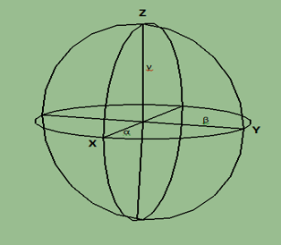
Figure: A Biaxial Crystal's Indicatrix. (An indicatrix is an imaginary ellipsoidal surface whose axes represent the refractive indices of a crystal for light passing through it in different directions.)
However, these optical directions and refractive indices are different from the crystallographic axes on the nature of the crystal system.
● Orthorhombic crystal system –optical directions correspond to crystallographic axes. Ex: X, Y or Z directions (α, β and γ refractive indices) may parallel to any of the crystallographic axes (a, b or c).
● Monoclinic crystal system – one of the X, Y and Z directions (α, β and γ refractive indices) is parallel to the b crystallographic axis while other two direction is not parallel to any crystallographic direction.
● Triclinic crystal system –none of the optical directions coincide with crystallographic axes.
There are two types of biaxial crystals such as, negative biaxial crystal and positive biaxial crystals. Negative biaxial crystals have their β closer to γ than to α. Positive biaxial crystals have their β closer to α than to γ.
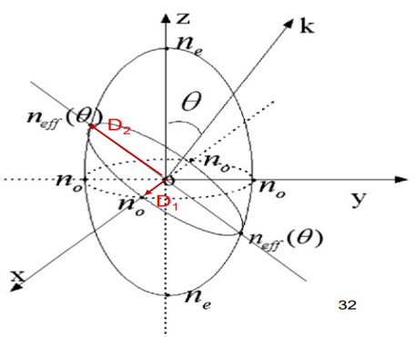
Light propagation in a uniaxial crystal

 index ellipsoid for uniaxial crystal
Take BBO as an example


(1) The index ellipsoid is utilized to determine the two refractive indices and two related D directions for the two independent plane waves that can propagate in the k direction.
(2) An ellipse is formed when the plane through the origin and perpendicular to k coincides with the index ellipsoid.
(3) D1 is perpendicular to the optical axis z and lies in the x-y plane. D2 is located in the z-k plane. D1 is known as the ordinary wave, whereas D2 is known as the remarkable wave.
(4) The intersection ellipse's two axes are
Double refraction
Double refraction, also known as birefringence, is an optical characteristic that occurs when a single ray of unpolarized light enters an anisotropic medium and splits into two rays, each going in a different direction. One ray (known as the extraordinary ray) is bent, or refracted, at an angle as it travels through the medium, while the other ray (known as the ordinary ray) travels through the medium unaltered. When two materials, glass and calcite, are compared, double refraction can be seen. Only one picture will be seen if a pencil mark is drawn on a sheet of paper and then covered with a piece of glass; but, if the same paper is coated with calcite and the crystal is orientated in a precise manner, two marks will become visible.
The phenomena of two-fold refraction through a calcite crystal is seen in the diagram. When an incident ray enters the crystal face at C, it splits into the ordinary ray CO and the extraordinary ray CE. However, if the incident ray enters the crystal parallel to its optic axis, the light ray will not be divided.
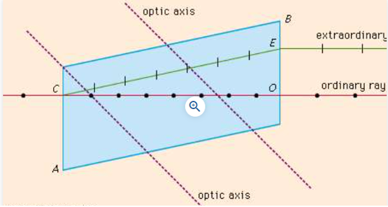
The ordinary and extraordinary rays are polarized in planes oscillating at right angles to each other in double refraction. Furthermore, the ordinary ray's refractive index (a number that determines the angle of bending specific to each medium) is constant in all directions; the extraordinary ray's refractive index varies depending on the direction taken because it has components that are both parallel and perpendicular to the crystal's optic axis. An extraordinary ray can move faster or slower than an ordinary ray because the speed of light waves in a medium is equal to their speed in a vacuum divided by the index of refraction for that wavelength.
The phenomenon of double refraction occurs in all transparent crystals except those of the cubic system, which are generally optically isotropic: ice, mica, quartz, sugar, and tourmaline are some well-known examples. Under certain conditions, other materials may become birefringent. When solutions containing long-chain molecules flow, they exhibit double refraction, a phenomenon known as streaming birefringence. When plastic materials made up of long-chain polymer molecules are compressed or stretched, they can become doubly refractive; this is known as photoelasticity. When put in a magnetic or electric field, or when subjected to external stress, some isotropic materials (such as glass) may display birefringence.
4.6.1 Double Refraction, Polarized Light
Light is split into two rays as it passes through a calcite crystal. The mechanism is known as twofold refraction, and it was first described by Erasmus Bartholinus in 1669. The calcite polarizes the two rays of light in such a way that the planes of polarization are mutually perpendicular. The two planes of polarization are also perpendicular to the plane of incidence for normal incidence (a Snell's law angle of 0°).
Snell's law predicts that the angle of refraction will be 0° for normal incidence (a 0° angle of incidence). At least one of the two beams must violate Snell's Law as we know it in the case of twofold refraction of a regularly incident ray of light. One of the two rays in calcite obeys Snell's Law; this ray is known as the usual ray (or O-ray). The other ray (and any other ray that does not follow Snell's Law) is a unique ray (or E-ray).
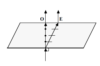
For conventional rays, the vibration direction is perpendicular to the ray path, as represented by the electric vectors in our drawings. The vibration direction of unusual rays is not perpendicular to the ray path. The wave normal is the direction perpendicular to the vibration direction. Although the ray path for extraordinary rays does not satisfy Snell's Law, the wave normal of unusual rays do. Snell's Law, in other words, relates the wave normal direction of the refracted ray to the wave normal direction of the incident ray.
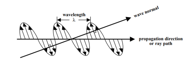
Except for those in the cubic system, all clear crystals have the property of double refraction. The image separation is not large enough to be discernible in most crystals. We will, however, use the O E propagation direction or ray path wavelength wave as an example. Ordinary Other optical phenomena that emerge from double refraction are studied in Optics 3 2. There will be one O-ray and one E-ray for hexagonal and tetragonal crystals. There will be two E-rays for orthorhombic, monoclinic, and triclinic crystals. The refractive indices of non-cubic crystals are generally affected by the direction of vibration. As a result, non-cubic crystals are considered to be optically anisotropic. The refractive indices of the two beams produced by double refraction are usually not the same in most circumstances. One of the two rays will have a greater refractive index (and therefore a lower velocity) than the other; this ray is known as the slow ray. The fast ray is the other ray.
Ordinary light does not have polarization. The electric vectors make all angles with the vertical when seen along a ray of light. Only vertical electric vectors exist in plane polarized light in the vertical plane. The vibration direction and the ray route are both included in the plane of polarization. Crystals, polarizing filters, and reflection can all polarize light. The vibration direction perpendicular to the plane of the ray path is favoured by reflected light, which is somewhat polarized (including both the incident and reflected rays).

Polarizing filters block any light that does not vibrate in the filter's favoured direction. Polarizing sunglasses selectively eliminate the polarized component of light reflected by horizontal surfaces by positioning their polarizing material vertically. Transparent crystals do not block light, regardless of its polarization plane. The phenomenon of double refraction divides the electric vectors of incident light into two perpendicular electric vectors in transparent anisotropic crystals. The two rays add together again when they emerge through the crystal, following the laws of vector addition. The combined emerging ray will not be equal to the incident ray since the two rays did not go through the crystal at the same velocity.

Polarizing microscopes have polarizing filters on both the bottom and top of the microscope stage. The polarizer is the lowest (fixed but rotating) filter, which on our microscopes has its polarization direction orientated E-W when viewed from above. (Be aware that the polarizing filters on certain older microscopes are orientated N-S!) When viewed from above, the upper filter (removable but not rotatable) is known as the analyzer, and its polarization direction is oriented N-S. Because the polarization directions of these two filters are perpendicular, unless the analyzer is removed or an anisotropic crystal is inserted between the two filters, all light going through the polarizer will be blocked by the analyzer polarized light.
It's worth noting that if the incident light is already polarized, there are specific orientations where all of the incident light is resolved along one of the crystal's two preferred vibration directions. There will be no double refraction in this situation, and the emerging ray will be identical to the incident light. If one of a crystal's two vibration directions is "parallel to the polarizer" (that is, parallel to the polarizing filter's plane of polarization), all light originating from the crystal will be polarized E-W and blocked by the analyzer. The crystal appears dark and is considered to be "at extinction" when this happens.
4.7.1 Nicol Prism
Nicol prism is an optical device which is used for producing and analyzing plane polarized light in practice.
Principal
The Nicol Prism is based on the double refraction phenomena.
Construction
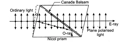
• The end faces PQ and RS of the calcite crystal PQRS are cut so that the angles in the primary section become 68° and 112° instead of 71° and 109° • The crystal is then cut diagonally into two halves. These parts' surfaces are first ground to make them optically flat, then polished.
• As a result, polished surfaces are joined using a special cement called as Canada Balsam.
4.7.2 Working
• When an unpolarized light beam strikes the face P′Q, it splits into two refracted rays known as O-ray and E-ray. These two beams are plane polarized, which means that their vibrations are at right angles to one another. The refractive index of Canada balsam cement is 1.55, which falls between the ordinary and extraordinary refractive indexes of 1.4864 and 1.4864, respectively. From the preceding description, it is evident that the Canada Balsam layer serves as an optically rarer medium for ordinary rays and an optically denser media for extraordinary rays.
• An ordinary ray of light passes from a denser to a rarer medium when it passes through the calcite crystal and into the Canada balsam cement layer. Furthermore, because the angle of incidence is greater than the critical angle, the incident ray is completely internally reflected by the crystal, leaving only exceptional rays to pass through the prism.
• As a result, the Nicol prism is used to generate a totally plane polarized wave.
Key takeaway:
● Two Nicol prisms are used to create plane polarized light and analyses it. In microscopy and polarimetry, the Nicol prism is utilized. As a result, calcium carbonate is the chemical composition of Nicol prism. CaCO3.
● The Nicol Prism is based on the Double Refraction phenomena. It's made of the calcite crystal PQRS, which is three times longer than it is wide. After that, the crystal is split diagonally into two pieces. These parts' surfaces are first ground to make them optically flat, then polished.
There are two types of rays: ordinary and remarkable. The ordinary ray has a constant refractive index of no, but the extraordinary ray has a refractive index that varies depending on the direction of light transmission in the crystal.
In a 2D anisotropic crystal, the refractive index of an e-ray and an o-ray changes when the angle with regard to the optic axis changes. The charts show how the values of the refractive indices fluctuate in different directions inside a crystal, and the forms of the refractive indices of both negative and positive crystals are shown.
The forms of the refractive indices for ordinary and extraordinary rays in an anisotropic crystal are shown in the diagram below (o-ray in blue and e-ray in red). On the vertical optic axis, the rays have the same refractive index. The green line denotes the direction in which the refractive indices are calculated inside the crystal. We could modify our direction inside the crystal by adjusting (specified as the angle between the optic axis and the green line). The refractive indices of the two rays differ at different angles, which is why we obtain two different forms. The o-ray refractive index is constant at all angles, but the e-ray refractive index is elliptical. At 90 degrees, the difference between the refractive indices of the two rays reaches its maximum.
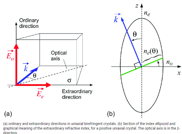
The second diagram depicts qualitatively how the refractive indices change for different directions in a crystal (which is described by the angle). If light is emitted from the origin in all directions, the variation of the refractive index with direction inside the crystal will result in different velocities in different directions (in the 2D example). The e-ray and the o-ray travel at different speeds. We may determine the velocity of the beam in that direction if we know the values of the refractive indices.
"ne(90)" denotes the e-ray refractive index, while "o" denotes the o-ray refractive index. The calculated value is displayed by varying. Any angle's "ne" value is displayed below the graphs. We could also figure out the refractive index forms of positive and negative crystals. We should alter the values of "ne(90)" and " " for positive crystals so that "ne(90)" > " ". We're dealing with negative crystals if the values are different.
This demonstration also depicts the locations within an anisotropic crystal where the beam velocities are the lowest and highest. The smallest velocity of light for positive crystals is at 90 degrees, while the maximum is along the optic axis, as seen in these figures. Because the velocity of light is inversely related to the refractive index, we get the lowest velocity along the optic axis and the highest velocity at 90 degrees for negative crystals.
Key takeaway:
- As one ray (named the unusual ray) travels through the medium, it is bent, or refracted, at an angle; the other beam (named the ordinary ray) continues through the medium unchanged.
- The portion of a ray split in half by double refraction that obeys regular refraction laws because its speed is constant in all directions through the doubly refracting medium.
4.9.1 Detection of Plane
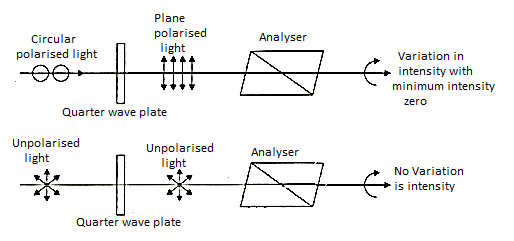
Light that is circularly and elliptically polarized (i) The light beam is permitted to fall on the Nicol prism in a plane polarized state. When the intensity of emitted light may be fully extinguished at two points in each rotation of a Nicol prism, the light is plane polarized. The light beam is allowed to land on a Nicol prism, resulting in circularly polarized light. If the intensity of emitted light remains constant when the Nicol prism is rotated, the light is either circularly polarized or unpolarized. The light is first transmitted through a quarter wave plate and then through a Nicol prism to distinguish between unpolarized and circularly polarized light. Because if beam is circularly polarized then after passing through quarter wave-plate an extra difference of λ/ 4 is introduced between ordinary and extraordinary component and gets converted into plane polarized. The light can thus be extinguished at two plates by spinning the Nicol. If the beam is unpolarized, it stays unpolarized after passing through the quarter wave plate, and there is no change in the intensity of emitted light when the Nicol is rotated.
4.9.2 Production of plane
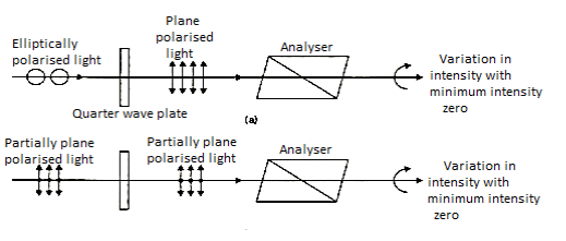
Light that is elliptically polarized. The light beam is permitted to pass through the Nicol prism. If the intensity of emitted light swings from maximum to minimum as the Nicol prism rotates, the light is either elliptically polarized or a mixture of plane polarized and unpolarized. The light is first transmitted via a quarter wave plate and then through a Nicol prism to distinguish between the two. Because, if beam is elliptically polarized, then after passing through quarter wave plate, an extra path difference of λ/ 4 is introduced between 0-ray and E-ray and get converted into plane polarized Thus, on rotating the Nicol, the light can be turned off in two places. If, on the other hand, the beam is a mixture of polarized and unpolarized, it remains a combination after passing through a quarter wave plate, and the Nicol intensity of radiated light fluctuates from maximum to minimum as the quarter wave plate is rotated.
4.10.1 Circularly Polarized Light
The fact that the absorption spectra of chiral substances measured with left- and right-hand circularly polarized light differ slightly can be explained by the fact that circularly polarized light is itself ‘chiral.' What is the reason for this? Chiral objects are helical objects. Take a look at the following photos of the bike stand:
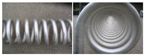
Any helical object, such as this one, has a mirror counterpart that is helical but rotates in the opposite direction. The original and the mirror image are not the same. In certain ways, every chiral molecule has this helicity built in.
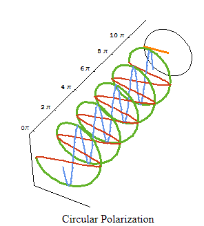
The left and right forms of circular polarization of light are mirror images of each other. Let's take a look at a circularly polarized light wave first. We solely consider the electromagnetic wave's electric field component. Consider superimposing (adding) two linearly polarized electromagnetic waves of equal amplitude and frequency (wavelength), but with the electric field vector oscillating in the xz plane in one case and the yz plane in the other. Assume that the waves go in the z direction. Voila! If the phase change between the two waves is exactly one quarter of the wavelength, you've got yourself a wave. We get a light wave in which the resulting electric field vector turns clockwise or anti-clockwise around a circle at any point along the z direction. This is why this light wave is referred to as circularly polarized. On the left, you can see an animation. If the two amplitudes are not quite equal, the electric field vector rotates clockwise or anti-clockwise on an ellipse, giving us elliptically polarized light.
4.10.2 Elliptical polarized light
Let's pretend we're looking into optical rotation at a wavelength where the medium absorbs some of the light's energy. Because a chiral medium absorbs left- and right-hand circularly polarized light differently (the CD effect), after passing through the absorbing chiral medium, the amplitudes of the exiting two circularly polarized components of the light beam are no longer equal. They have a distinct amplitude and phase shift. As a result, we end ourselves in a predicament similar to the one illustrated in the right-hand animation (different amplitudes). In other words, the outgoing light beam is now elliptically polarized rather than linearly polarized. See the animation below, which was made with Mathematica in the same way as the one before but with one of the circular components losing amplitude as it goes through the optically active medium. At any fixed place, the ellipticity of the outgoing light is plainly evident in the electric field vector (orange).
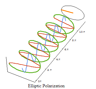
Because various absorption coefficients at that wavelength (or frequency) induce elliptic polarization, the amount of ellipticity is proportional to the strength of the circular dichroism. The distinction is that the CD is calculated by taking the difference between the absorption of left- and right-hand circularly polarized light. Ellipticity is the result of performing the experiment with both light polarizations at the same time (by starting out with linearly polarized light).
4.11.1 Phase Retardation Plates
The Polarization State of light can be modified by the Birefringence of crystals, which is particularly useful in many applications. Birefringent wave plates or retardation plates are the names given to this sort of optical component (or just wave plates or retarders for short).
The extraordinary and ordinary rays' velocity through birefringent materials are inversely proportional to their refractive indices. When the two beams merge, the velocity difference causes a phase discrepancy. In the case of an incident linearly polarized beam this is given by a=2 d(ne-no)/(-phase difference; d-thickness of waveplate; ne, no-refractive indices of extraordinary and ordinary rays respectively;
  -wavelength). At any specific wavelength the phase difference is governed by the thickness of the waveplate.
Red Optronics provides the following waveplates: octadic-wave ( /8), quarter-wave (
 /4), half-wave (
 /2) and full-wave (
 ) plates.
4.11.2 Half Wave Plate
The half wave plate can be used to rotate the polarization state of a plane polarized light as shown in Figure below.
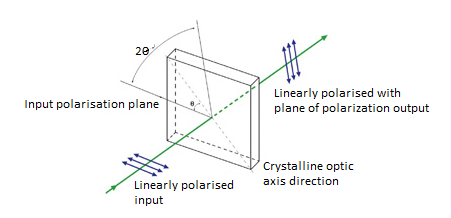
Suppose a plane-polarized wave is normally incident on a wave plate, and the plane of polarization is at an angle q with respect to the fast axis, as shown. After passing through the plate, the original plane wave has been rotated through an angle 2.
A half-wave plate is useful for rotating the polarization plane of a polarized laser to any desired plane (especially if the laser is too large to rotate). Vertical polarization is used in the majority of big ion lasers. Simply insert a half-wave plate in the beam with its fast (or slow) axis 45° to the vertical to achieve horizontal polarization. The  /2 plates can also change left circularly polarized light into right circularly polarized light or vice versa. The thickness of half waveplate is such that the phase difference is 1/2 wavelength (
 /2, Zero order) or certain multiple of 1/2-wavelength [(2n+1)
 /2, multiple order].
4.11.3 Quarter Wave Plate
Quarter wave plate are used to turn plane-polarized light into circularly polarized light and vice versa. To do this, we must orient the wave plate so that equal amounts of fast and slow waves are excited. We may do this by orienting an incident plane-polarized wave at 45° to the fast (or slow) axis, as shown in Figure below. When a  /4 plate is double passed, i.e., by mirror reflection, it acts as a
  /2 plate and rotates the plane of polarization to a certain angle, i.e., 90°. This scheme is widely used in isolators, Q-switches, etc.
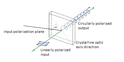
The thickness of the quarter waveplate is such that the phase difference is 1/4 wavelength ( /4, Zero order) or certain multiple of 1/4-wavelength [(2n+1)
 /4, multiple order].
4.12.1 Babinet–Soleil Compensators
A Babinet–Soleil compensator (or simply Babinet compensator) is a set of birefringent plates that can be used as a waveplate that can be adjusted (retarder plate). It consists of three birefringent plates, all constructed of the same material (e.g., crystalline quartz): one plane-parallel plate and two wedges, with the latter's optical axis oriented perpendicular to the plane-parallel plate. The effective thickness can be adjusted by moving one of the wedges in a direction perpendicular to the beam. Typically, a translation stage with a micrometres screw is used to move that wedge. There are also computer-controlled motorized versions available.
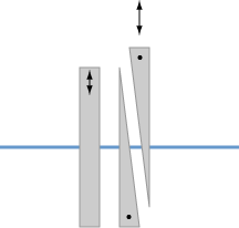
Figure: Three birefringent plates make up the Babinet–Soleil compensator.
Overall zero retardance, i.e., no changes in polarization direction of a beam, can be obtained by adjusting the insertion of the movable wedge so that the overall optical path length in the wedges is the same as in the plane-parallel plate. A retardance of either sign can be obtained in a specific range by shifting the which in or out, for example. With a controllable degree of retardation, the device can function as an effective zero-order waveplate. This is effective over a wide range of optical wavelengths.
In contrast to a Wollaston polarizer, the wedge angles are so narrow that there is no considerable spatial separation of polarization components, i.e., no considerable transverse beam offset. It's also worth noting that, whereas the optical path length of a single wedge is determined by its transverse location, the same is not true for a pair of wedges. As a result, homogeneous retardance over a large aperture can be achieved. If the plates are constructed with enough precision, there is no substantial beam deflection.
Although the Babinet–Soleil compensator can be utilized over a wide range of wavelengths, the resultant retardance is wavelength dependent.
Anti-reflection coatings are commonly used on the plates to reduce reflection losses and eliminate interference effects.
Compensators for several wavelength ranges, including the infrared, are available.
4.12.2 Uses of babinet compensator
Babinet–Soleil compensators can be employed in any application where a variable degree of retardation for a constant wavelength (e.g., for correcting other birefringence) or the capacity to obtain a specific level of precise retardation for varied wavelengths is required. Ellipsometry and polarimetry are two examples.
Such a device can also be used to measure the retardance of other optical elements (such as fixed waveplates) by determining how much additional retardance is necessary for compensation, if this can be determined, for example, using the scale of the utilized micrometre screw. The user can link the wedge location to the retardance at different wavelengths using the tuning data provided by the compensater.
4.13.1 Analysis of Polarized Light
Polarization is a phenomena generated by the wave nature of electromagnetic radiation, according to physics. Sunlight is an example of an electromagnetic wave since it travels through the vacuum to reach the Earth. Because an electric field interacts with a magnetic field, these waves are known as electromagnetic waves. You will learn about two types of waves in this article: transverse waves and longitudinal waves. You’ll also learn about polarized1on and light that is plane polarized.
4.13.2 Transverse waves
Transverse waves are waves in which the movement of the particles is perpendicular to the wave's motion direction.
Example 1: When you throw a stone, it creates ripples in the water.
Example 2: sound waves moving across the air.
Longitudinal waves occur when the medium's particles move in the same direction as the waves.
The interaction of electric and magnetic fields travelling across space is known as light. A light wave's electric and magnetic vibrations are perpendicular to each other. The magnetic field goes in one direction and the electric field in the other, but they are always perpendicular. So, we have an electric field in one plane, a magnetic field perpendicular to it, and a travel direction that is perpendicular to both. Electric and magnetic vibrations can happen in a variety of planes. Unpolarized light is defined as a light wave that vibrates in more than one plane. Unpolarized light sources include the light emitted by the sun, a lamp, and a tube light. The direction of propagation is constant, but the planes on which the amplitude occurs change, as seen in the graphic below.
The image here shows its various types:
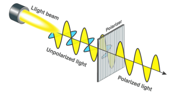
A polarize wave is the other type of wave. Light waves that vibrate in a single plane are known as polarize waves. Plane polarize light is made up of waves with the same direction of vibration for all of them. A plane polarize light vibrates on only one plane, as shown in the image above. Polarization is the process of converting non-polarized light into polarize light. The equipment you see, such as the purple blocks, are employed to polarize light.
4.13.3 Polarization Applications
The following are some examples of polarization applications:
• Polarization is used to reduce glare in sunglasses, and Polaroid filters are utilized in the plastics industry to do stress analysis tests.
• Polarization is used to create and display three-dimensional movies.
• Polarization is used to distinguish between longitudinal and transverse waves.
• Polarization is used in infrared spectroscopy.
• It's used to research earthquakes in seismology.
• In chemistry, polarization techniques are used to determine the chirality of organic molecules.
Key takeaways:
• Transverse waves travel along the x axis but oscillate in the z-y plane.
• The speed of propagation of a transverse wave is given by the equation v = fλ.
• The wave's motion is perpendicular to the direction of energy transmission.
4.14.1 Rotatory Polarization
A polarization rotator is an optical device that rotates the polarization axis of a linearly polarized light beam at a predetermined angle. The Faraday effect, birefringence, or total internal reflection can all be used to create such devices. Because laser beams are linearly polarized, it is frequently essential to rotate the original polarization to its orthogonal alternative, linearly polarized light rotators have found significant use in modern optics.
4.14.2 Optical rotation
The plane of polarized light is rotated by some chemicals, usually organic (particularly those having asymmetric carbon atoms). Optical rotation is the term for this phenomena, and such molecules are known as optically active chemicals. The concentration of a material in a solution is calculated by measuring the angle of rotation.
Many factors influence the measured angle of rotation:
• The sample's type or nature (example: sugar solution)
• The optical active components' concentration
• The sample tube's length.
• The light source's wavelength
• The sample's temperature
The nature of a sample is described by adding the substance's specific optical rotatory power (or specific rotation), which is defined as
] Θ α λ = γ. l α in SI units: rad m2 kg-1
(Notice: 2π rad = 360 0 (deg of angle))
Where α is the angle of rotation in rad, γ is the mass concentration in kg/m3, and l is the length of the sample tube in m. Specific rotation is determined at a specified temperature Θ (usually 20 0C) and a wavelength of light source (usually sodium lamp with its D line at 589 nm).
Some substances rotate the light to the right (or clockwise) as viewed looking towards the light source, we sign this rotation and α as +, some to the left (or anticlockwise), signing α as -.
In practical measurements readings are taken at different units: α in 0 (deg), γ in g/cm3, l in dm and so [] 0 20 α D is usually tabulated in 0 cm3 /g dm.
Substance in a solution  | Specific rotation |
Sucrose |  |
Glucose | +52/74 |
Fructose | -93.78 |
Maltose | +137.5 |
Lactose | +55.3 |
Dextrose | +194.8 |
For example: Sucrose (cane sugar) solution 0 20 α D = + 66.54 0 /dm at a concentration of 1 g/cm3.
The following table shows the effect of the wavelength of a light source on sugar solutions:
Description of the light source | Wavelength[nm] | Specific rotation  |
Mercury, green | 546.23 | +78.4178 |
Sodium, yellow | 589.44 | +66.5885 |
HeNe Laser | 632.99 | +57.2144 |
Near Infrared (NIR) | 882.60 | +28.5462 |
Notice the high precision of specific rotation determined with modern polarimeters. Temperature dependence of specific rotation is for sugar solutions as follows: α (t) = α (20.0 0C) [1.0 – 0.000471 (t – 20.0)] or calculated for some temperatures of a sucrose solution at some concentration:
Temperature  | Rotation of a sucrose solution  |
20 | 40.000 |
21 | 39.981 |
25 | 39.906 |
With increasing temperature, the rotation of the sucrose solution decreases. Temperature has a negligible influence as well.
4.15.1 Biot-Savart law
In physics, the Biot-Savart law is a fundamental quantitative relationship between an electric current and the magnetic field it generates, based on tests conducted by French scientists Jean-Baptiste Biot and Félix Savart in 1820.
A magnetic field, or an area in space around the conductor in which magnetic forces may be observed, is created by an electric current running in a conductor, or a moving electric charge. The sum of all contributions from each small element, or segment, of a current-carrying conductor can be regarded the value of the magnetic field at a point in the surrounding space. The Biot-Savart law describes how the magnetic field value at a given place in space from a single short segment of current-carrying conductor is affected by each component that influences the field. To begin with, the value of the magnetic field at a given position is proportional to the current in the conductor as well as the length of the current-carrying section in question. The value of the field is also affected by the direction of the particular point in relation to the current segment. The field is largest when the line from the point to the short segment of current creates a 90° angle with the current segment or lies straight out from it. The field of the current segment decreases as the angle decreases, eventually becoming 0 when the point is on a line of which the current element is a segment. Furthermore, the magnetic field at a given point is proportional to its distance from the current element. The magnetic field is four times smaller at twice the distance, or the value of the magnetic field is inversely proportional to the square of the distance from the current source.
In a specific example, the Biot-Savart rule is used by adding up the contributions to the magnetic field at a particular position from all of the small current segments that make up a specific conductor of any shape. For example, the value of the magnetic field at a nearby location is directly proportional to the current and inversely proportional to the perpendicular distance from the wire to the provided point when a very long straight wire is carrying current. Ampère's law is a good example.
4.15.2 What is the Formula of Biot-Savart’s Law?
Consider the current-carrying wire I in the diagram above, which is pointing in a specified direction. Take a little piece of wire with a length of ds. This element's direction is parallel to that of the current, forming a vector I ds.
Biot-Law Savart's can be used to determine the magnetic field produced at a given position by this little element. Let the angle between the two be and the position vector of the point in question drawn from the current element be r. After that,

Where
μ0 is the permeability of free space and is equal to 4π × 10-7 TmA-1.
The magnetic field always travels in a plane perpendicular to the element line and position vector. The right-hand thumb rule determines it, with the thumb pointing in the direction of conventional current and the other fingers indicating the direction of the magnetic field.
When plane polarized light passes through any substance, the plane of vibration of the plane polarized light changes (rotates). The property of a substance rotating the plane of vibration is known as "Optical Activity."
The optical rotation, or rotation of the polarized light plane, is depicted here.
Optical activity refers to a substance's ability to rotate the plane of polarization of plane-polarized light. Optimally active compounds are those that have the ability to rotate the plane of polarized light flowing through them. Optically active crystals include quartz and cinnabar, whereas optically active liquids include sugar and tartaric acid aqueous solutions.
There are two categories of optically active chemicals.
- Dextrorotatory substances – Right-handed or dextrorotatory substances rotate the plane of polarization of the light towards the right.
- Levorotatory substances – Left-handed or left-handed substances spin the plane of polarization of light toward the left.
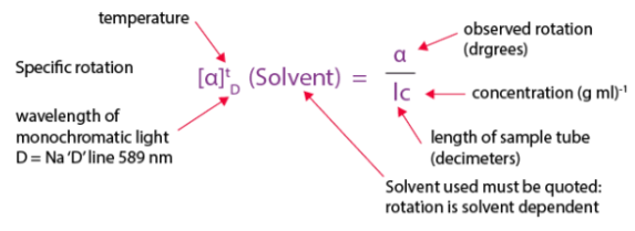
The ability of a compound to rotate the plane of polarized light is known as optical activity. This feature is caused by the interaction of polarized light's electromagnetic radiation with the chiral molecule's electrons' unsymmetric electric fields.
The quantity of molecules exerting their impact, which is dependent on concentrations, will definitely influence the rotation observed. According to the formula below, observed rotations are translated into particular rotations that are a characteristic of the compounds.
4.17.1 Calculating Angles of Rotation
This tutorial series will show how to use a differential wheeled robot to create polygonal and circular orbits. You'll go over various regular polygons and circular examples, first using mathematics and then by executing some Simple IDE code examples. These tutorials are designed for Parallax's ActivityBot, but the concepts may be applied to a variety of other robots (such as the S2) with a little tweaking. First, we'll need to study and analyze the problem of how to program rotation. We should be able to program the robot to rotate to the correct direction (clockwise or counterclockwise) corresponding to the various angles 0 ° < ω < 360 ° that we want to turn.
4.17.2 Rotation of ActivityBot ω degrees
In Go Certain Distances, you can see that the drive_goto(26, -25) command makes the ActivityBot execute a 90-degree right turn. Let’s see this example in closer detail and try to create a mathematical formula to calculate the appropriate number of “ticks” that correspond to some angle ω.
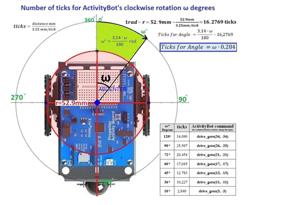
The ActivityBot rolls its wheels on the red circle as it rotates (radius: 52.9 mm). Each wheel will move a distance equal to the radius r of the red circle if the robot makes a 1 radian (rad) turn. As a result, 1 rad rotation of the ActivityBot equals movement of the distance wheels:
r =52.9 mm = 52.91/3.25 ticks = 16.2769 ticks
Changing rad to degrees, we take the formula:
Ticks for Angle = ω * 0.284
So, if we want to program the ActivityBot to rotate ω degrees we can multiply by 0.284 in order to find the appropriate number of wheel ticks.
To verify the above formula, we can see that a rotation of 90 degrees = 90 * 0.284 ticks = 25.56 ticks = 26 ticks (rounded up).
A table with relevant information for the next activities may be seen in the image above. We've included an enlarged version of it below:
 | Ticks | Activity Bot command (for coaster clockwise rotation change the sign) |
120  | 34,090 | Drive_goto (34, -34) |
90  | 25,567 | Drive_goto (26, -25) |
72  | 20,454 | Drive_goto (21, -21) |
60  | 17,045 | Drive_goto (17, -17) |
45  | 12,783 | Drive_goto (13, -13) |
36  | 10,227 | Drive_goto (11, -11) |
10  | 2,840 | Drive_goto (3, -3) |
Change the signals for counterclockwise rotation, according to the language in the chart under "ActivityBot command." This involves changing positive values to negative and negative values to positive in order to reverse the direction of motion. For example, drive_goto (34, -34) would become drive_goto (-34, 34), etc.
In 1819, Fresnel entered his work on diffraction into a competition held by the French Academy of Sciences on the subject. A number of prominent supporters of Newton's corpuscular model of light were on the judging panel, and one of them, mathematician Siméon-Denis Poisson, pointed out that Fresnel's model predicted an apparently absurd result: if a parallel beam of light falls on a small spherical obstacle, there will be a bright spot at the centre of the circular shadow—a spot nearly as bright as if the obstacle were not there. After an experiment by French physicist François Arago, the spot (later known as Poisson's spot) was discovered, confirming Fresnel's victory in the competition.
Despite this victory for the wave theory of light, the properties of polarized light seemed to be explained solely by the corpuscular theory, and Fresnel and Arago began studying the rules of polarized light interference in 1816. He was the first to achieve circularly polarized light in 1817. As a result of this observation, he came to the conclusion that light was a transverse wave rather than a longitudinal wave, as previously thought. (Young had come to the same conclusion on his own.)
Fresnel joined Arago on a government committee to upgrade French lighthouses in 1819, following Arago's advice. In 1821, he invented the dioptric system, which uses the refracting qualities of glass to create a device. He ringed a centre bull's-eye lens with a series of concentric glass prismatic rings on a lens panel. The panel concentrated light output by the lamp over a wide horizontal angle, as well as light that would normally escape to the sky or the sea, into a narrow horizontal pencil beam. In 1824, Fresnel was able to make numerous revolving beams from a single light source by spinning a number of lens panels around the lamp, which was an improvement over the mirror's single beam. To gather more of the light that was wasted vertically, he placed triangular prism parts above and below the main lens that refracted and reflected the light. He significantly increased the angle of incidence at which rays shining up and down might be captured and made to emerge horizontally by doing so. As a result, the full Fresnel catadioptric system was born.
Despite the fact that his work in optics got little public acknowledgment during his lifetime, Fresnel claimed that nothing could match to the joy of discovering a theoretical truth or experimentally proving a calculation.
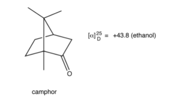
Observed rotation of an optically active compound, measured using the polarimeter, depends on the experimental conditions and, therefore, is not a characteristic property of the compound. Specific rotation (symbol: [α]λT) of an optically active compound is defined as follows:

α = observed rotation measured using a polarimeter
l = length of sample tube
C = concentration, if a solution of the compound is used for the experiment, or density, if a neat sample of the compound is used
T = Temperature (usually 25 ºC)
λ = wave length of the light used (usually 589 nm)
Specific rotation of a compound is a characteristic property of the compound as long as the temperature, the wave length of the light, and, if a solution is used for the experiment, the solvent are specified. The units of specific rotation are degreesmLg-1dm-1. However, since the units of specific rotation are always the above, traditionally, specific rotation is reported without units.
E.g.:
This tutorial thoroughly explains the Laurent half-shade polarizer's fundamentals. The polarimeter is made up of a collimated linearly polarized light source (S, L, and P) that is fed through the sample tube T (which rotates the polarization if the sample is optically active), polarized (A), and observed via a telescope E.

You're looking for the maximum and minimum brightness in this basic configuration (without the half-shade A), which tells you that the analyzer A is perfectly aligned with the output rotation.
The half-shade H, which is made up of two half-disks of equally absorbent material, sits between the polarized light source and the sample. The glass half, ACB, allows polarized light to flow through unaffected. The other half, ADB, is composed of quartz with optical axes running along AOB and DOC and is cut to half-wave-plate thickness; in essence, if the original polarization was along SOP, it is reflected over into ROQ, i.e., orthogonal to SOP, in the quartz half.
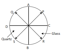
The point where both half of the image are exactly equal in brightness, i.e., where the analyzer is at exactly 45°45° from the polarization of both sides of the image, is what you're looking for with this version of the polarimeter.
The half-utility shade's is dependent on the apparatus' sensitivity. The experimenter must look for the greatest or minimum brightness with a traditional polarimeter, which is a difficult task: On the one hand, you don't have an objective standard (you're comparing to other angles right next to the one you're trying), but more importantly, you're taking variations around a point where the signal appears quadratic, so even large changes in the angle won't make a significant difference in the output.
Assume that your eyes can detect brightness differences of ten percent or greater. This means that on a non-shaded polarimeter, any points in the cos2()>1 region will appear to be the maximum, therefore that is your range of uncertainty, which looks like this:
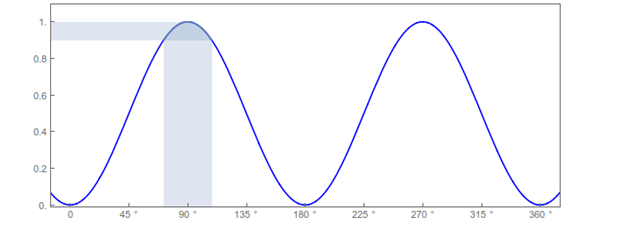
The half-shade, on the other hand, compares two separate signals at the point where they match, giving you a quick reference (the signals are equal or not, and you don't have to fumble with the analyzer angle to see if you're in the right spot or not).
More crucially, you're comparing two signals with a positive slope, which greatly improves sensitivity. If you preserve the same =10%=10% deviation of either signal with respect to the baseline, you get something like this:
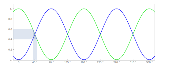
It is immediately obvious that the larger slope makes the 'shadow' on the angle axis, which gives the range of uncertainty is much smaller. In fact, this is really over-counting the uncertainty, since you're probably able to detect δ=10% differences in the brightness of the two halves, which means that you should slice in two the vertical range and therefore (because of linearity) the horizontal range should also be half as big.
It's important to emphasize that this is not just a one-off sort of difference: in fact, the difference in performance increases more and more as the sensitivity in the detector (i.e., your eyes, and eventually a pair of photodiodes on the two halves of the half-shade) improves. This is because the relationship between the angle uncertainty δθ and the signal uncertainty δ is quadratic for the non-shaded apparatus, since
δ∼12δθ2,
From the Taylor expansion of the cosine about its maximum, whereas the relationship is linear,
δ∼δθ,
For instances where the slope is linear This is the essence of the procedure, and it is repeated over and over in metrology: you get better measurements using differential measurements of quantities that have a sensitive change with regard to the thing you care about, rather than looking at the extremes where the change is shallower.
References:
1. Classical Electrodynamics by J.D. Jackson (Willey)-2007
2. Foundation of electromagnetic theory: Ritz and Milford (Pearson)-2008
3. Electricity and Magnetism: D C Tayal (Himalaya Publication)-2014
4. Optics: A.K. Ghatak (McGraw Hill Education)- 2017
5. Electricity and Magnetism: Chattopadhyaya, Rakhit (New Central)-2018