Unit - 1
Coordination Chemistry
1.1.1 What are Coordination Compounds?
Coordination compounds are chemical compounds made up of an array of anions or neutral molecules bound together by coordinate covalent bonds to a central atom. Coordination complexes are another name for coordination compounds. The ligands are the molecules or ions that are bound to the central atom (also known as complexing agents).
Important Terms Involving Coordination Compounds
The meanings of some key words in coordination compound chemistry can be found below.
Coordination Entity
A coordination object is a chemical compound in which the central ion or atom (or coordination centre) is bound to a certain number of atoms, molecules, or ions.
Some examples of such coordination entities include [CoCl3(NH3)3], and [Fe(CN)6]4-.
Central Atoms and Central Ions
The central atoms and ions, as previously mentioned, are the atoms and ions to which a certain number of atoms, molecules, or ions are bound.
The central atoms or ions in coordination compounds are usually Lewis Acids, which may serve as electron-pair acceptors.
Ligands
The ligands are the atoms, molecules, or ions that are bound to the coordination centre or the central atom/ion.
These ligands can be simple ions or molecules (like Cl– or NH3), or they can be relatively large molecules like ethane-1,2-diamine (NH2-CH2-CH2-NH2).
1.1.2 Coordination Number
The total number of sigma bonds by which the ligands are bound to the coordination centre is referred to as the coordination number of the central atom in the coordination compound.
Nickel, for example, has a coordination number of 4 in the coordination complex [Ni(NH3)4]2+.
Coordination Sphere
The non-ionizable portion of a complex compound that is made up of a central transition metal ion surrounded by atoms or groups enclosed in square brackets.
When written together, the coordination sphere is formed by the coordination centre, the ligands attached to the coordination centre, and the net charge of the chemical compound as a whole.
A counter ion is normally present with this coordination sphere (the ionizable groups that attach to charged coordination complexes).
Example: [Co(NH3)6]C/3 – coordination sphere
Coordination Polyhedron
The coordination polyhedron is the geometric shape created by the ligands' attachment to the coordination centre.
Tetrahedral and square planar spatial arrangements are examples of such spatial arrangements in coordination compounds.
Oxidation Number
When all the electron pairs donated by the ligands are withdrawn from the central atom, the charge associated with it can be determined to determine its oxidation number.
For example, the oxidation number of the platinum atom in the complex [PtCl6]2- is +4.
Homoleptic and Heteroleptic Complex
The coordination complex is called a homoleptic complex when the coordination centre is bound to just one kind of electron pair donating ligand group, for example: [Cu(CN)4]3- [Cu(CN)4]3- [Cu(CN)4]3-
2. The coordination compound in question is called a heteroleptic complex when the central atom is bound to several different forms of ligands, such as [Co(NH3)4Cl2]+.
Properties of Coordination Compounds
This section discusses the general properties of coordination compounds.
1. The presence of unpaired electrons in the electronic transitions of the transition elements causes the coordination compounds produced by them to be coloured. Iron(II) complexes, for example, can be green or light green in colour, whereas coordination compounds containing iron(III) are brown or yellowish-brown in colour.
2. Because of the presence of unpaired electrons, the resulting coordination complexes have a magnetic nature when the coordination centre is a metal.
3. Coordination compounds are characterised by a wide range of chemical reactivity. They will take part in both inner-sphere and outer-sphere electron transfer reactions.
4. Complex compounds with specific ligands have the ability to catalyse or stoichiometrically help in the transformation of molecules.
1.1.3 Double Salts and Coordination Complex
Double Salts
In aqueous liquids, double salts are fully ionizable, and each ion in the solution gives the corresponding confirmatory test.
Example: Potash Alum is double sulphate. It is K2SO4.Al2(SO4)3.24H2O on Ionization it gives:
K+, SO2−4 and Al+3 ions which response to the corresponding tests.
1.1.4 Coordination Complex
In aqueous solutions, coordinate complexes are only partially ionizable. These produce a complexion that isn't fully ionised.
Example: Potassium Ferrocyanide. [K4Fe(CN)6] It ionizes to give K+ and [Fe(CN)6]−4 [ferro cyanide ions]
Types of Coordination Complexes
Cationic complexes: In this co-ordination sphere is a cation. Example: [Co(NH3)6]Cl3
Anionic complexes: In this co-ordination sphere is Anion. Example: K4[Fe(CH)6]
Neutral Complexes: In this co-ordination sphere is neither cation or anion. Example: [Ni(CO)4]
Homoleptic complex: The complex consist of a similar type of ligands. Example: K4[Fe(CN)6]
Heteroleptic complexes: These consists of different types of ligands. Example: [Co(NH3)5Cl]SO4
Mononuclear complexes: In this co-ordination sphere has single transition metal ion. Example: K4[Fe(CN)6]
Polynuclear complexes: More than one transition metal ion is present. Example:

Polynuclear complexes
1.1.5 IUPAC Nomenclature of Coordination Compounds
Rules For Naming Coordination Compound
The standard rules for the nomenclature of coordination compounds are outlined in the following sections.
1. In the naming of complex coordination complexes, the ligands are often written before the central metal ion.
2. When more than one ligand is bound to the coordination centre, the names of the ligands are written in an alphabetical order that is unaffected by the numerical prefixes that must be added to the ligands.
3. When a coordination compound contains a large number of monodentate ligands, the prefixes di-, tri-, tetra-, and so on are used to indicate the number of ligands.
4. Prefixes of the form bis-, tris-, and so on are used because there are several polydentate ligands bound to the central metal ion.
5. The names of the anions in a coordination compound must all end in the letter 'o,' which usually replaces the letter 'e.' As a result, the sulphate anion must be written as "sulfato" and the chloride anion as "chlorido."
6. In coordination compounds, the neutral ligands NH3 (ammine), H2O (aqua or aquo), CO (carbonyl), and NO are given particular names (nitrosyl).
7. The name of the central metal atom is written after the ligands have been identified. The suffix ‘-ate' is used if the complex has an anionic charge associated with it.
8. If the Latin name of the metal occurs, it takes precedence when writing the name of the central metallic atom in an anionic complex (with the exception of mercury).
9. The oxidation state of the central metal atom/ion must be defined using roman numerals enclosed in a pair of parentheses.
The cationic entity must be written before the anionic entity if the coordination compound is followed by a counter ion.
Examples of Naming Coordination Compounds
Some examples of the nomenclature of coordination compounds can be found below.
K4[Fe(CN)6]: Potassium hexa cyanide ferrate (II)
[Ni(CN)4]−2: Tetra cyanie Nickelate (II) ion.
[Zn(OH)4]−2: Tetra hydroxide zincate (II) ion.
[Ni(CO)4]: Tetra carbonyl Nickel (O).
What are Ligands in Coordination Compounds?
Ligands are the atoms, ions, and molecules that accompany the central transition metal ion. They serve as a Lewis base, donating electron pairs to the transition metal ion, forming a dative bond between the ligands and the transition metal ion. As a result, these compounds are known as coordination complexes.
See also: Ligands
Types of Ligands
Based on the nature of the bond between the ligand and the central atom, ligands are classified as follows:
Ligands can be further classified as:
Unidentate Ligands
Unidentate ligands are ligands that only have one atom that can bind to the coordination centre. A good example of an unidentate ligand is ammonia (NH3). Cl–, H2O, and other unidentates are popular.
Bidentate Ligands
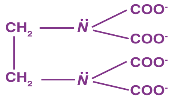
Bidentate ligands, such as ethane-1,2-diamine, have the ability to bind to the central atom through two separate donor atoms.
The ion oxalate is a bidentate since it can bind to the central atom of a coordination compound through two atoms. Ethane-1, 2-diamine:
Polydentate Ligands
Many donor atoms in some ligands may bind to the coordination centre. Polydentate ligands are the name given to these ligands.
The EDTA4- ion (ethylene diamine tetraacetate ion) is a polydentate ligand with four oxygen atoms and two nitrogen atoms that can bind to the coordination centre.
Chelate Ligand
A chelate ligand is described as a polydentate ligand that binds to the same central metal atom through two or more donor atoms. The denticity of such ligands refers to the atoms that ligate to the metal ion.
Ambidentate Ligand
Some ligands can bind to the central atom by using atoms from two separate elements.
The SCN– ion, for example, can bind to a ligand through the nitrogen or sulphur atoms. Ambidentate ligands are a type of ligand that has two ends.
1.1.6 Isomerism in Coordination Compounds
Isomers are two or more compounds that have the same chemical formula but a different atom structure. Coordination compounds primarily show two forms of isomerism, namely stereo-isomerism and structural isomerism, as a result of this disparity in atom arrangement.
Stereoisomerism
Stereoisomers are coordination compounds with the same chemical and chemical bonds in a different spatial structure. Optical isomerism and geometrical isomerism are two types of isomerism.
Optical Isomerism in Coordination Compounds
Optical isomers, also known as enantiomers, are isomers that form non-superimposable mirror images. There are two kinds of these.
1 The dextro or ‘d' or ‘+' isomer rotates plane-polarized light in a clockwise direction.
2 The leavo isomer, also known as the ‘l', ‘-‘ isomer, rotates plane-polarized light in an anti-clockwise direction.
The racemic mixture is the equimolar mixture of the ‘d' and ‘l' isomers.
Example of Optical Isomerism:
Geometrical Isomerism
Owing to various potential geometric configurations of the ligands, geometrical isomerism is observed in heteroleptic complexes (complexes with more than one type of ligand).
This behaviour is most common in coordination compounds with coordination numbers of 4 and 6. Complexes with coordination number 4 have geometrical isomerism:
Example:

ML6 octahedral complex does not show geometrical isomerism. MA2B4 complex shows cis-trans isomerism.
Example: [Co(NH3)4Cl2]+
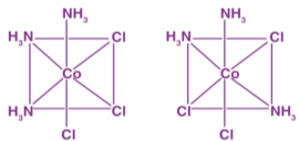
MA3B3 complex shows facial-meridional isomerism.
Structural Isomerism
Coordination compounds with the same chemical formula but a different atom structure exhibit structural isomerism. There are four different styles of these:
Linkage Isomerism
Coordination compounds with Ambidentate ligands exhibit linkage isomerism.
For example[Co(NH3)5No]So4 and [Co(NH3)5ONO]So4
Coordination Isomerism
The interchange of ligands between cationic and anionic entities of different metal ions found in coordination compounds is known as incoordination isomerism.
For example: [Co(NH3)6][Cr(CN)6] and [Cr(NH3)6][Co(CN)6].
Ionisation Isomerism
When the counter ion in a complex salt that is a possible ligand replaces the ligand, ionisation isomerism occurs.
For example: [Co(NH3)5(SO4)]Br and [Co(NH3)5Br]SO4.
Solvate Isomerism
Solvate isomers are a form of ionisation isomerism in which the number of solvent molecules directly bound to the metal ion determines how the compounds differ.
For example:
[Co(H2O)6]Cl3
[Co(H2O)5Cl]Cl2.H2O
[Co(H2O)4Cl2]Cl.2H2O
[Co(H2O)3Cl3].3H2O
Ligand Isomerism
In this type, ligands show isomerism.
For Example:
1.1.7 Werner’s Theory
Werner's theory, which explains the structure of coordination compounds, was introduced by Alfred Werner in 1898.
Werner's Experiment: All three chloride ions were converted to AgCl by combining AgNO3 (silver nitrate) with CoCl3•6NH3 (silver chloride). When AgNO3 was combined with CoCl3•5NH3, however, two moles of AgCl were formed.
In addition, one mole of AgCL was formed by mixing CoCl3•4NH3 with AgNO3. Based on this observation, Werner proposed the following theory:
Postulates of Werner’s Theory
1 The coordination compound's central metal atom has two types of valencies: primary and secondary linkages or valencies.
2 Negative ions satisfy primary linkages, which are ionizable.
3 Secondary linkages cannot be ionised. Negative ions fulfil these needs. In addition, the secondary valence of any metal is set and equal to its coordination number.
4 The ions bound to the metal by secondary linkages have distinct spatial structures that correspond to different coordination numbers.
Difference between Primary and Secondary Valency in Coordination Compounds
Werner’s Theory | |
Primary valency | Secondary valency |
These are ionizable | These are Non-ionizable |
Satisfied by charged ions | Satisfied by ligands |
Primary valency does not help in the structure of complex | Secondary valency helps in structure |
It can also function as a secondary valence | It can not function as a primary valency |
Example: CoCl3.6NH3 is Werner complex.
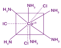
Coordination polyhedra are a type of spatial arrangement. The ions outside the square brackets are counter-ions, and the terms within the square brackets are coordination complexes.
Limitations of Werner’s Theory
1. It fails to describe coordination compounds' magnetic, colour, and optical properties.
2. It failed to understand why coordination compounds aren't formed by all elements.
3. It didn't clarify how coordination compounds' bonds have directional properties.
4. This hypothesis does not account for the complex's stability.
5. This theory was unable to understand the complexity of complexes.
1.1.8 Effective Atomic Number Rule
Sidgwick proposes the Effective Atomic Number Rule. After the ligand donates electrons, the cumulative number of electrons passed by the central transition metal ion is an appropriate atomic number.
The effective atomic number of a complex is equal to the atomic number of the nearest inert gas.
Example: Calculate the effective atomic number of the following complexes:
K4[Fe(CN)6]
[Co(NH3)]Cl3
1. K4[Fe(CN)6]
Number of electrons in Fe2+ = 24
Number of electrons by Six CN = 2×6 = 12
Total number of electrons possessed by Fe2+ = 24 + 12
Therefore, the effective atomic number = 36.
2. [Co(NH3)]Cl3
Number of electrons in Co+3 = 24
Number of electrons by Six NH3 = 2×6 = 12
Total number of electrons possessed by Co+3 = 24 + 12
Therefore, the effective atomic number = 36.
1.1.9 Magnetic Properties of Complexes
1. A paramagnetic complex is one in which the central transition metal ion has unpaired electrons.
2. A diamagnetic complex is one in which the central transition metal ion has no unpaired electrons.
3. The spin only formula is used to measure a complex's magnetic moment.
[n(n+2)] M = BM
BM stands for Bohr Magneton.
The magnetic moment of complex compounds is determined by the following factors:
There is only one form of hybridization.
2 The central transition metal ion's oxidation state.
3 The number of electrons that are not paired.
Spectro Chemical Series
The series of increasing order of field strength of ligands is known as Spectrochemical series. It is I– < Br– < SCN– < Cl– < S-2 < F– < OH– < C2O-24 < H2O < NCS− < (EDTA)-4 < NH3 < en < CN < CO
A complex is created in a series of steps. Each phase step is reversible, and the stepwise formation constant is the equilibrium constant. Consider the development of the ML4 complex.
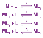
= K1 K2 K3 K4 and 1/ = Instability constant is the overall formation constant or stability constant.
Factors Affecting Complexes' Stability
1. The central transition metal ion is small and has a strong nuclear charge.
2. The CFSE (crystal field stabilising energy) should be increased.
3. Chelating ligand-containing complexes are more stable.
4. Octahedral complexes are more stable than tetrahedral complexes.
Check out Crystal Field Theory as well.
The Color of Complexes is a term that refers to the colour of a complex.
Complexes with unpaired electrons in the central transition metal ion display colour. It's a move from d to d. The colour of complexes is determined by:
In a transition metal ion, the number of unpaired electrons is measured.
ligands' assets
Example: [Ni(H2O)6]+2+en(aq)→[Ni(H2O)4en]+2 – Green Pale blue
1.1.11 Bonding in Metal Complexes [Metal Carbonyls]
Complexes in which carbon monoxide acts as ligands are metal carbonyls
Example: [Ni(CO)4] Tetracarbonyl Nickel (0) and [Fe(CO)5] Penta Carbonyl Iron (0) In these complexes, complexes, a′σ‘ bond is formed by the overlapping of vacant ‘d’ orbital of metal ion and filled orbital of C-atom (carbon).
A π bond is formed by the lateral overlapping of filled inner orbitals of metal ion and vacant of the carbon atom. Thus synergic bonding exist in metal carbonyls.
Applications of Coordination Compounds
Coordination compounds' unique properties, as described in the previous subsection, make them extremely useful in a variety of processes and industries. Some of these coordination compound applications are listed below.
1 Because of the colour of coordination compounds comprising transition metals, they are widely used in industries for material coloration. In the dye and pigment industries, they are used.
2 In the electroplating process, some complex compounds with cyanide as a ligand are used. These compounds are also beneficial in the field of photography.
3 In the extraction of many metals from their ores, coordination complexes are extremely useful. Nickel and cobalt, for example, can be extracted from their ores using hydrometallurgical methods involving coordination compound ions.
Applications In Biology
1 Haemoglobin is made up of a complex ion called Haeme, which has a tetrapyrrole Porphyrin ring structure with a central Fe2+ ion.
2 Vitamin B12 has a coordination number of 6 and is made up of a tetrapyrrole porphyrin ring complex with a central Co+3 ion.
Applications In Laboratory
Ni+2 is estimated using a complexing agent Dimethylglyoxime (DMG). The hardness of water is estimated using complexes of Ca++, Mg++ with ED↑A
In Medicine: Cisplatin is used in the treatment of cancer.
In Photography: Developing of the film involves complex formation.
In Metallurgy: In the extraction of gold, silver by Mac Arthur Forest Process involves a complex of cyanide ions.
1.2.1 VALENCE BOND THEORY - DEFINITION
A significant number of coordination compounds' structure and magnetic properties are explained by the valence bond theory. The structure of coordination compounds and the bond linkages were explained using the valence bond theory. According to valence bond theory, a metal atom or ion may use its (n-1)d, ns, np, nd orbitals for hybridization to yield a collection of identical orbitals of definite geometry such as octahedral, tetrahedral, square planar, and so on when it is influenced by ligands. The ligand orbitals that can donate electron pairs for bonding can overlap with the hybridised orbitals.
1.2.2 POSTULATES OF VALENCE BOND THEORY - DEFINITION

The valence-bond theory was based on the Heitler-London model of covalent bonds. Linus Pauling's suggestion that atomic orbitals mix to form hybrid orbitals, such as the sp,sp2,sp3,dsp3,and d2sp3 orbitals, was the final major step in the development of this theory.
Some coordination complexes, such as the Co(NH3)63+ ion, are simple to apply the valence-bond principle to. The electron structure of the transition-metal ion Co3+ is first examined: [Ar]d6 is a character in the game [Ar]d6 The valence-shell orbitals are then examined, and the 4s and 4p orbitals are both empty. The following electron configuration is obtained by concentrating the 3d electrons in the dxy,dxz, and dyz orbitals in this subshell. The 3dx2y2,3dz2,4s,4px,4py, and 4pz orbitals are then combined to form a series of empty d2sp3 orbitals pointing toward the octahedron's corners. Both of these orbitals will accept a pair of non-bonding electrons from a neutral NH3molecule, resulting in a complex with a filled shell of valence electrons on the cobalt atom.
1.2.3 FORMATION OF OCTAHEDRAL COMPLEX - DEFINITION

Some coordination complexes, such as the Co(NH3)63+ ion, are simple to apply the valence-bond principle to. The electron configuration of the transition-metal ion Co3+:[Ar]d6 is the first step. The valence-shell orbitals are then examined, and the 4s and 4p orbitals are both empty. The following electron configuration is obtained by concentrating the 3d electrons in the dxy,dxz, and dyz orbitals in this subshell. The 3dx2y2,3dz2,4s,4px,4py, and 4pz orbitals are then combined to form a series of empty d2sp3 orbitals pointing toward the octahedron's corners. Each of these orbitals will accept a pair of non-bonding electrons from a neutral NH3 molecule, resulting in a complex with a filled shell of valence electrons on the cobalt atom.
1.2.4 OUTER ORBITAL COMPLEXES - DEFINITION
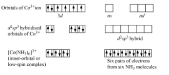
Complexes that use outer d-orbitals in complexes, e.g., [Co(NH3)6]3+. The hybridisation is shown in the diagram.
CHARACTERISTICS OF OUTER ORBITAL COMPLEXES - DEFINITION
Inner d-orbitals, (n-1) d-orbitals, or outer d-orbitals, nd-orbitals, can be involved in the hybridization. Low spin complexes and high spin complexes, also known as inner and outer orbital complexes, are formed in these two ways. The form is tetrahedral and the hybridisation is sp3.
1.2.5 INNER-ORBITAL COMPLEXES - DEFINITION

A complex, typically of a transition element, in which the hybridization of the central metal atom utilizes d-orbitals from the shell inside that of the outermost occupied shell.
CHARACTERISTICS OF INNER ORBITAL COMPLEXES - DEFINITION
Hybridisation is dsp2 and shape is square planar.
1.2.6 HYBRIDISATION OF COMPLEX COMPOUNDS ON THE BASIS OF MAGNETIC BEHAVIOUR - DEFINITION
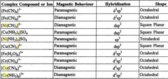
1.2.7 FORMATION OF TETRAHEDRAL COMPLEX ON THE BASIS OF VBT - DEFINITION
A central atom is located at the middle of four substituent atoms that form the corners of a tetrahedron in tetrahedral molecular geometry. The bond geometry is common, particularly in complexes with metals in the d0 or d10 electron configuration. It's most often found in outer orbital complexes with sp3 hybridisation.
1.2.8 FORMATION OF SQUARE COMPLEX ON THE BASIS OF VBT - DEFINITION
A central atom is surrounded by constituent atoms that form the corners of a square on the same plane in square planar molecular geometry. Transition metal complexes with a d8 configuration are prone to this geometry. Rh(I), Ir(I), Pd(II), Pt(II), and Au are examples of this (III). In theory, flattening a tetrahedron will result in square planar geometry. As a result, the interconversion of tetrahedral and square planar geometries provides a route for tetrahedral compounds to be isomerized. Tetrahedral nickel(II) complexes, such as NiBr2(PPh3)2, for example, undergo this reversible transition. Inner orbital complexes are where it normally forms. dsp2 is the hybridization.
1.2.9 DRAWBACKS OF VBT - DEFINITION
It fails to clarify carbon's tetravalency; it does not mention electron energies; and it makes claims about electrons being localised to particular locations.
1.2.10 COORDINATE BOND INTERMS OF VALENCE BOND APPROACH - DEFINITION
The number of vacant orbitals on the central metal atom (or) ion is sufficient to accommodate the electrons donated by the ligands. As a result, the ligand forms a coordinate bond with the central atom, in which the electrons are exchanged only by the ligands and not by the central atom.
1.2.11 MAGNETIC MOMENTS OF COORDINATION COMPOUNDS - DEFINITION
Calculate the charge on the metal ion. Write the electronic structure of the metal ion. Using the law, draw the electronic diagram of the metal ion's orbitals.
Then figure out how many unpaired electrons there are (n).
Use the magnetic moment formula (n(n+2)).
1.2.12 FAILURE OF VALANCE BOND THEORY - EXAMPLE
Valence bond theory fails to account for the Tetrahedral, Pyramidal, and Bent forms of polyatomic molecules like methane, ammonia, and water, which are Tetrahedral, Pyramidal, and Bent, respectively.
1.3.1 Pauling Principle of Electro neutrality:
According to Linus Pauling's theory of electroneutrality, each atom in a stable material has a charge that is close to zero. Linus Pauling first proposed it in 1948, and it was later revised. The principle has been used to predict which of a group of molecular resonance structures is the most important, to explain the stability of inorganic complexes, and to explain the existence of -bonding in compounds and polyatomic anions containing silicon, phosphorus, or sulphur bonded to oxygen; it is still used in the context of coordination complexes. Modern computational methods, on the other hand, show that many stable compounds have a charge distribution that is greater than the theory predicts (they contain bonds with greater ionic character).
1.3.2 Application of principle:
Explanation of the structure adopted by hydrogen cyanide
HCN and CNH are two different structures for hydrogen cyanide that differ only in the position of the hydrogen atom. The CNH structure results in formal charges of -1 on carbon and +1 on nitrogen, which would be partly offset by nitrogen's electronegativity, and Pauling measured the net charges on H, N, and C as -0.79, +0.75, and +0.04 respectively. In comparison, the structure HCN, which has hydrogen bound to carbon, has formal charges of 0 on carbon and nitrogen, and the influence of the nitrogen's electronegativity will make the charges on H, C, and N +0.04, +0.17, and -0.21. As a result, the triple-bonded structure is preferred.
Relative contribution of resonance structures (canonicals)
The cyanate ion (OCN) can be given three resonance structures, for example:
The nitrogen atom in the rightmost structure in the diagram has a charge of -2. Using the electroneutrality theorem, this can be described as a minor contributor. Furthermore, since the most electronegative atom can bear the negative charge, the triple bonded structure on the left is expected to play a significant role.
Stability of complexes
If the bonding to the ammonia molecules was electrostatic, the hexammine cobalt(III) complex [Co(NH3)6]3+ would have all of its charge on the central Co atom. A covalent linkage, on the other hand, will result in a charge of -3 on the metal and +1 on each nitrogen atom in the ammonia molecules. Using the electroneutrality principle, it is assumed that the Co-N bond would have 50% ionic character, resulting in a cobalt atom with no charge. The N-H bond will have a 17 percent ionic character due to the difference in electronegativity, resulting in a charge of 0.166 on each of the 18 hydrogen atoms. This effectively spreads the 3+ charge around the complex ion's "surface."
π-bonding in oxo compounds of Si, P, and S
In a 1952 paper, Pauling used the theory of electroneutrality to say that pi bonding can be found in molecules with four Si-O bonds, for example. Since their electronegativity (electron withdrawing power) was higher than that of silicon, the oxygen atoms in such molecules would form polar covalent bonds with the silicon atom. The charge buildup on the silicon atom due to the difference in electronegativity was determined by Pauling to be +2. The electroneutrality theory led Pauling to believe that charge transfer from O to Si would take place through d orbitals forming a -bond, and that this -bonding was responsible for the Si-O bond shortening.
1.3.3 The adjacent charge rule
Another of Pauling's principles for deciding whether a resonance structure would make a substantial contribution was the "adjacent charge law." It was first published in 1932 and claimed that structures that put opposite-sign charges on neighbouring atoms were unfavourable.
Naming Transition Metals
Many transition metals come in a variety of cation types. Iron, for example, comes in two forms: Fe2+ and Fe3+. As a result, when naming an ionic compound containing iron, it is important to specify the metal's oxidation number. After the cation, the oxidation number appears as a Roman numeral in parenthesis. The oxidation number of metals is the same as the charge. Fe2+ in a chloride-containing compound has the formula FeCl2 and is known as iron(II) chloride. Iron(III) oxide is formed when the cation Fe3+ is combined with oxygen and has the formula Fe2O3.
The method for naming polyatomic ions-containing ionic compounds is the same as for simple ions. As a result, CaCO3 is known as calcium carbonate (NH4) Pb2+ combined with SO42- (PbSO4) is known as lead(II) sulphate, and 2HPO4, a compound with two polyatomic ions, is known as ammonium hydrogen phosphate.
1st example: For each of the following ionic compounds, write the proper chemical formula: Aluminum oxide, copper(II) chloride, and iron(III) oxide are all examples of oxides.
a. Aluminum is 3+, although oxide is 2-; Al2O3. b. Based on the oxidation state, copper is 2+ and chloride is 1-; CuCl2. c. The oxidation state of iron is 3+, while the oxide state is 2-; Fe2O3.
Example 2: For each of the following ionic compounds, write the proper chemical name: a. Li2S; b. NiCl2; c. FeO.
Solution 2: a. Since we aren't using multipliers, this is just lithium sulphide. b. Since nickel is 2+ in this compound, we must call it nickel(II) chloride. c. Since the iron in this compound is 2+, we must call it iron(II) oxide.
Naming Coordination Compounds
More complex coordination compounds are made up of an atom or ion (usually a metal) and a ligand-like sequence of bound molecules or anions. The donor atom is the atom in a ligand that is bound to the central atom or ion. Several donor atoms, which may be the same or different, are connected to a standard complex. The coordinate covalent bonds (dipolar bonds) between the ligands and the central atom are referred to as coordination.
The following are the principles for naming a teamwork compound:
1. The ligands are numbered before the metal ion when naming a complex ion.
2. List the ligands' names in the following order: neutral, negative, positive. If multiple ligands of the same charge form exist, they are called alphabetically. (Numerical prefixes have no impact on the ordering.)
3. Monodentate ligands with several occurrences are given a prefix based on the number of occurrences: di-, tri-, tetra-, penta-, or hexa. Polydentate ligands (e.g., ethylenediamine, oxalate) obtain bis-, tris-, tetrakis-, and other forms of bis-, tris-, tetrakis-, and other forms of bis-, tris-, tetrakis-, and other forms of bis-, tris-, te
4. Anions end in the suffix -ido. This takes the place of the final "e" when the anion ends in "-ate" (e.g., sulphate becomes sulfato) and "-ide" when the anion ends in "-ide" (cyanide becomes cyanido).
5. With a few exceptions, neutral ligands are assigned their normal names: NH3 becomes ammine, H2O becomes aqua or aquo, CO becomes carbonyl, and NO becomes nitrosyl.
6. Write the central atom's or ion's name. The central atom's name will end in -ate if the complex is an anion, and its Latin name will be used if it is available (except for mercury).
7. If the oxidation state of the central atom must be defined (it may be one of many or zero), write it in parentheses as a Roman numeral (or 0).
8. Separate the words "cation" and "anion" at the end (if applicable).
Anionic Ligands
Ligands that act as anions which end in "-ide" are replaced with an ending "-o" (e.g., Chloride → Chloro). Anions ending with "-ite" and "-ate" are replaced with endings "-ito" and "-ato" respectively (e.g., Nitrite → Nitrito, Nitrate → Nitrato).
Table: Anionic Monodentate Ligands | |||
Molecular Formula | Ligand Name | Molecular Formula | Ligand Name |
F- | Fluoro | OH- | Hydroxo |
Cl- | Chloro | SO42- | Sulfato |
Br- | Bromo | S2O32- | Thiosulfato |
I- | Iodo | NO2- | Nitrito-N-; Nitro |
O2- | Oxo | ONO- | Nitrito-O-; Nitrito |
CN- | Cyano | SCN- | Thiocyanato-S-; Thiocyanato |
NC- | Isocyano | NCS- | Thiocyanato-N-; Isothiocyanato |
Neutral Ligands
Most neutral molecules that are ligands carry their normal name. The few exceptions are the first four on the chart: ammine, aqua, carbonyl, and nitrosyl.
Table: Select Neutral Monodentate Ligands. Note: Ammine is spelled with two m's when referring to a ligand. Amines are a class of organic nitrogen-containing compounds. | |
Molecular Formula of Ligand | Ligand Name |
NH3 | Ammine |
H2O | Aqua |
CO | Carbonyl |
NO | Nitrosyl |
CH3NH2 | Methylamine |
C5H5N | Pyridine |
Polydentate ligands follow the same rules for anions and neutral molecules.
Table: Select Polydentate ligands | |
Short name | Extended name |
En | Ethylenediamine |
ox2- | Oxalato |
EDTA4- | Ethylenediaminetetraacetato |
Ligand Multiplicity
The prefixes di, tri, and so on represent the number of ligands present in the complex. Polydentates with a prefix already in their name are an exception (en and EDTA4- are the most common). Place the ligand's name in parentheses and use bis (for two ligands), tris (for three ligands), and tetrakis (for four ligands) to indicate how many of these are present in a coordination complex (for four ligands).
Table: Prefixes for indicating number of ligands in a complex. | ||
Number of Ligands | Monodentate Ligands | Polydentate Ligands |
1 | mono | - |
2 | di | bis |
3 | tri | tris |
4 | tetra | tetrakis |
5 | penta | pentakis |
6 | hexa | hexakis |
Prefixes are often placed before the ligand name and are ignored when sorting ligands alphabetically. It's worth noting that the term "mono" is rarely used. The ions [FeCl(CO)2(NH3)3]2+[FeCl(CO)2(NH3)3]2+[FeCl(CO)2(NH3)3]2+[FeCl(CO)2(NH3)3]2+[FeCl(CO)2(NH3)3]2+[FeCl(CO)2(NH3)3]2+[FeCl(CO)2(NH3)3] Often remember that ligands come first, followed by metals.
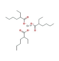
Example coordination compound: Chromium(III) 2-ethylhexanoate molecule.
Example:
Write a proper chemical name for each of the following coordination compounds:
a. [NiCl4]2−
b. Pt(NH3)2Cl4
c. [Pt(NH3)2Cl2]Cl2.
Solution:
The ion tetrachloridonickelate(II). Inside the parentheses is the complex ion, an anion. The suffix -ate must be added to the metal's name.
Diamminetetrachloroplatinum (Diamminetetrachloroplatinum) (Diamminetetrachlorop (IV). This is a molecule that is completely neutral. The ligands have a cumulative charge of -4. As a result, the oxidation number of platinum is +4.
c. Chloride of diamminedichloroplatinum(II). The number of ions and atoms is the same in this case. The brackets, as well as the platinum's different oxidation number, result in a very different name.
A subscript to the Greek symbol put before the ligand name indicates the number of ligands attached to more than one metal (bridging ligands). As a result, Al2Cl4(2-Cl)2 is used to characterise the dimer of aluminium trichloride.
1.5.1 Isomerism in Coordination Compounds
Isomerism refers to a process in which compounds with the same molecular formula but different structures are referred to as isomers. Isomers are chemical and physical compounds that have different properties.
There are two types of isomers:
Structural isomerism: Different types are as follows:-
Stereoisomerism: Different types are as follows:-
Structural isomerism: The compounds have same molecular phenomenon but different structures
Ionization isomerism: they differ in productions of ions in aqueous solution
For example:à [CoBr(NH3)5]SO4 and [Co (NH3)5SO4 ]Br are ionization isomers when dissolved in water
[CoBr(NH3)5]SO4 à[CoBr(NH3)5]2+ + SO42-
[Co (NH3)5SO4 ]Bràà[CoSO4 (NH3)5]2+ + Br-
Hydrate or solvate isomerism: in this they differ in number of molecules of water of crystallization
For example: [Cr(H2O)6]Cl3 and [Cr(H2O)5Cl]Cl2H2Oare hydrate isomers
When dissolved in water
[Cr(H2O)6]Cl3à[Cr(H2O)6] + 3Cl- (no water molecule )
[Cr(H2O)5Cl]Cl2H2Oà[Cr(H2O)5Cl]+2Cl+H2O(will give one water molecule )
Coordination isomerism: In terms of coordination bodies, they vary.
For example:[Co(NH3)6] [Cr(CN)6] and :[Co(CN)6] [Cr(NH3)6] are coordination isomers
Linkage isomerism: It's the same for ambidentate ligands, which vary in their attachment point.
For example, in case of CN(cyano) and in case of NC (isocyano)
Stereoisomerism: The molecular formulas of these compounds are identical, but the spatial configurations of the ligands vary.
It is of two types:
Geometrical isomerism: It's because the geometrical arrangements of ligands around the central metal atom vary.
it is of further two types :
Cis : when the similar ligands are on adjacent position
Trans : Cis and trans isomers are seen below while identical ligands are in opposite positions (this is shown by compounds with coordination numbers 4 and 6).
Example: [Pt (NH3)4Cl2]
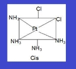
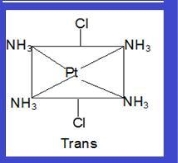
Another type of Geometrical isomerism that occurs in octahedral compounds in Ma3b3 like [Co(NH3)3(NO3)3].
It can be of two types :
Fac :In this three donor atoms of same ligands occupy adjacent positions at corners of an octahedral face
mer :In this three donor atoms of same ligands occupy positions around the meridian of an octahedron.
Planar Isomers
Geometrical isomers are metal complexes that vary only in whether their ligands are adjacent to one another (cis) or directly across from one another (trans) in the coordination sphere of the metal. Square planar and octahedral complexes benefit the most from them.
Since all vertices of a square are equal, it makes no difference the vertex in a square planar MA3B complex is occupied by the ligand B; therefore, only one geometrical isomer is possible in this case (and in the analogous MAB3 case). Since they can be superimposed simply by rotating the complex in space, all four structures shown here are chemically identical:

There are two possible isomers for an MA2B2 complex: either the A ligands are next to each other (cis), in which case the B ligands must also be cis, or the A ligands are across from each other (trans), in which case the B ligands must also be trans. Despite the fact that the cis isomer can be drawn in four different ways and the trans isomer in two, all members of each set are chemically equivalent:
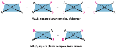
They are radically different configurations of atoms in space and there is no way to transform the cis structure to the trans by spinning or flipping the molecule in space. cis-Pt(NH3)2Cl2, also known as cisplatin, and trans-Pt(NH3)2Cl2, which is toxic rather than therapeutic, are perhaps the best-known examples of cis and trans isomers of an MA2B2 square planar complex.

Cisplatin, an anticancer drug, and its inactive trans isomer. Cisplatin is particularly effective against tumours of the reproductive organs, which usually affect people in their 20s and have a reputation for being difficult to treat. Lance Armstrong, for example, was cured by cisplatin chemotherapy after being diagnosed with metastasized testicular cancer in 1991 and offered a 50% chance of survival.
There is only one possible structure for square planar complexes containing symmetrical bidentate ligands, such as [Pt(en)2]2+, in which curved lines connecting the two N atoms indicate the ethylenediamine ligands:

Octahedral Isomers
Cis and trans isomers can be found in octahedral complexes. Only one structure is possible for octahedral complexes in which only one ligand is different from the other five, similar to square planar complexes (MA5B). Despite the fact that we normally draw an octahedron in such a way that the four "in-plane" ligands are distinct from the two "axial" ligands, all six vertices of an octahedron are identical. As a result, any representation of an MA5B structure can be superimposed on any other simply by rotating the molecule in space. The following are two of the several possible MA5B structure orientations:

Two isomers are possible when two ligands in an octahedral complex vary from the other four, resulting in an MA4B2 complex. Both B ligands may be trans or cis. This form of system includes cis- and trans-[Co(NH3)4Cl2]Cl:

When another A ligand is replaced with B, an MA3B3 complex is formed, with two possible isomers. The fac isomer is one in which the three ligands of each kind occupy opposite triangular faces of the octahedron (for facial). The three ligands of each type lie on the meridian if the complex were regarded as a sphere in the other, which is known as the mer isomer (for meridional):

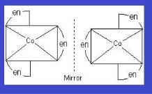
Optical isomers: If they have a chiral nucleus, they may also exhibit optical isomerism. They will rotate the plane of polarised light if they have a chiral nucleus.
Example: [Co(en)3]
1.6.1 Geometrical isomerism in complexes with coordination number 4
I Geometrical isomerism does not exist in tetrahedral complexes.
(ii) Geometrical isomerism is observed in square planar complexes of the formula [MX2L2] (where X and L are unidentate). In a cis isomer, the two X ligands may be located next to each other, while in a trans isomer, they may be arranged opposite each other, as in,
(iii) The [MABXL] square planar complex (where A, B, X, L are unidentate ligands) has three isomers, two cis and one trans.
e.g., [Pt(NH3) (Br)(Cl)(Py)].
1.6.2 Geometrical isomerism in complexes with coordination number 6
[Co(NH3)4Cl2)+ is an octahedral complex with the formula [MX2L4], in which the two X ligands can be directed cis or trans to each other.
[MX2A2] Octahedral complexes, where X denotes unidentate ligands and A denotes bidentate ligands. [CoC12(en)2]
If three donor atoms of the same ligands occupy adjacent positions at the corners of an octahedral face in octahedral complexes of formula [MA3X3]. It is known as facial (fae) isomer when the positions are near the octahedron's meridian, and it is known as meridional (mer) isomer when the positions are around the octahedron's meridian. [Co(NH3)3(NO2)3] is an example.
(ii) Optical isomerism The chiral complexes are those that have chiral structures. When mirror images can't be superimposed on top of each other, this problem occurs. Enantiomers are mirror images of each other. The two forms are known as dextro (d) and laevo (l).
Optical isomerism can be seen in tetrahedral complexes with the formula [M(AB)2] and octahedral complexes (cis form).
Question 1
Write the formulas for the following coordination compounds:
(i) Tetraamminediaquacobalt(III) chloride
(ii) Potassium tetracyanonickelate(II)
(iii) Tris(ethane−1,2−diamine) chromium(III) chloride
(iv) Amminebromidochloridonitrito-N-platinate(II)
(v) Dichloridobis(ethane−1,2−diamine)platinum(IV) nitrate
(vi) Iron(III) hexacyanoferrate(II)
ANSWER:
(i) 
(ii) 
(iii) 
(vi) 
(v) 
(vi) 
Question 2
Write the IUPAC names of the following coordination compounds:
(i) [Co(NH3)6]Cl3
(ii) [Co(NH3)5Cl]Cl2
(iii) K3[Fe(CN)6]
(iv) K3[Fe(C2O4)3]
(v) K2[PdCl4]
(vi) [Pt(NH3)2Cl(NH2CH3)]Cl
ANSWER:
(i)Hexaamminecobalt(III) chloride
(ii) Pentaamminechloridocobalt(III) chloride
(iii) Potassium hexacyanoferrate(III)
(iv) Potassium trioxalatoferrate(III)
(v) Potassium tetrachloridopalladate(II)
(vi) Diamminechlorido(methylamine)platinum(II) chloride
Question 3:
Indicate the types of isomerism exhibited by the following complexes and
draw the structures for these isomers:
K[Cr(H2O)2(C2O4)2
[Co(en)3]Cl3
[Co(NH3)5(NO2)](NO3)2
[Pt(NH3)(H2O)Cl2]
ANSWER:
(i) Both geometrical (cis-, trans-) isomers for  can exist. Also, optical isomers for cis-isomer exist.

Trans-isomer is optically inactive. On the other hand, cis-isomer is optically active.

(ii) Two optical isomers for  exist.
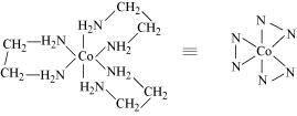
Two optical isomers are possible for this structure.

(iii) 
A pair of optical isomers:

It can also show linkage isomerism.
 and
and
It can also show ionization isomerism.

(iv) Geometrical (cis-, trans-) isomers of  can exist.

Question 4
Give evidence that [Co(NH3)5Cl]SO4 and [Co(NH3)5SO4]Cl are ionization isomers.
ANSWER:
When ionization isomers are dissolved in water, they ionize to give different ions. These ions then react differently with different reagents to give different products.
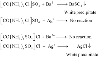
Question 5
Explain why the [Ni(CN)4]2 ion with a square planar structure is diamagnetic and the [NiCl4]2 ion with a tetrahedral geometry is paramagnetic using valence bond theory.
ANSWER:
Ni is in the +2 oxidation state i.e., in d8 configuration.

There are four CN ions in total. As a result, it may have either a tetrahedral or a square planar geometry. Since the CN ion is a heavy field ligand, it allows unpaired 3d electrons to pair.

It now undergoes dsp2 hybridization. Since all electrons are paired, it is diamagnetic.
In case of [NiCl4]2−, Cl− ion is a weak field ligand. Therefore, it does not lead to the pairing of unpaired 3d electrons. Therefore, it undergoes sp3 hybridization.

Since there are 2 unpaired electrons in this case, it is paramagnetic in nature.
Question 6
[NiCl4]2− is paramagnetic while [Ni(CO)4] is diamagnetic though both are tetrahedral. Why?
ANSWER:
Despite the fact that both [NiCl4]2 and [Ni(CO)4] are tetrahedral, their magnetic properties are distinct. This is due to the existence of ligands being different. Cl is a weak field ligand that does not cause unpaired 3d electrons to pair. As a result, [NiCl4]2 is a paramagnetic compound.

In Ni(CO)4, Ni is in the zero oxidation state i.e., it has a configuration of 3d8 4s2.

CO, on the other hand, is a potent field ligand. As a result, it allows unpaired 3d electrons to pair. It also allows the 4s electrons to migrate to the 3d orbital, causing sp3 hybridization to occur. Since there are no unpaired electrons in this situation, [Ni(CO)4] is diamagnetic.
Question 7:
[Fe(H2O)6]3+ is strongly paramagnetic whereas [Fe(CN)6]3− is weakly paramagnetic. Explain.
ANSWER:
In both  and
and  , Fe exists in the +3 oxidation state i.e., in d5 configuration.

Since CN− is a strong field ligand, it causes the pairing of unpaired electrons. Therefore, there is only one unpaired electron left in the d-orbital.

Therefore,

On the other hand, H2O is a weak field ligand. Therefore, it cannot cause the pairing of electrons. This means that the number of unpaired electrons is 5.
Therefore,

Thus, it is evident that  is strongly paramagnetic, while
  is weakly paramagnetic.
The ease with which ligands can be substituted in coordination complexes is referred to as lability. In the following example, Scandium is referred to as "labile."
[Sc(OH2)6] [Sc(OH2)6] [Sc(OH2)6
6 NaSCN + Cl3 —> Na3
3 NaCl + [Sc(SCN)6] (quick!)
The term lability refers to the ease with which metal-ligand bonds can be broken. The term "labile" refers to a compound in which the metal-ligand bonds are easily broken. The term "inert" refers to a compound in which the metal-ligand bonds are more difficult to break.
By comparing the factors that control bond strengths in ionic complexes to observations about the rates of reaction of coordination complexes, Henry Taube (Nobel Prize, 1983) attempted to understand lability. He noticed some unsurprising incidents. He also came up with some new ligand field theory conclusions.
Many M+1 ions (M = metal) are more labile than many M+3 ions, according to Taube. In forming coordination complexes, metal ions act as electrophiles or Lewis acids, and ligands act as nucleophiles or Lewis bases, which isn't shocking. In other words, higher-charged metals should be stronger Lewis acids and therefore bind ligands more tightly.
There were, however, exceptions to the general rule. Taube discovered that Mo(V) compounds are more labile than Mo(III) compounds, for example. That implies that there's more going on here than charge effects.
The size of the ion is another aspect that influences the strength of ionic bonds. Ions with smaller atomic radii, on average, form stronger bonds than ions with larger radii. The ions Al3+, V3+, Fe3+, and Ga3+ are all around the same scale, according to Taube. These ions all exchange ligands at a similar rate. Since they have the same charge and radius, this isn't shocking.
Cr3+, on the other hand, is around the same size as those ions and has the same charge, but it is much less labile. Again, due to basic electrostatic considerations, there are exceptions to our usual expectations.
Furthermore, transition metals in the second and third rows (Y-Cd and Ac-Hg) are much more inert than those in the first row (Sc-Zn). That's a little odd, given how much larger the lower metals are than the first row metals.
It does, however, provide insight into other factors that influence lability. Second- and third-row metals have much higher d orbital splitting energies than first-row metals, according to ligand field theory. This is often described in terms of larger atoms' diffuse orbitals forming stronger bonds with ligands, reminding us that we're not only concerned with electrostatic interactions.
Taube wondered if the electron configuration of a compound affected whether it was labile or inert. Taube's lability rules are based on this concept.
Metals like Ni2+ and Cu2+, for example, are extremely labile. For those substances, the d orbital splitting diagrams will have d electrons in the eg set. Remember that the eg set is formed by interactions with the ligand donor orbitals, and it corresponds to an antibonding degree.
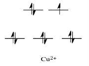
By comparison, V2+ is rather inert. The d orbital splitting diagram in this case has electrons in the t2g set, but none in the eg set.
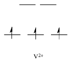
As a result, having electrons at a higher energy level weakens the bond between the ligand and the antibonding eg level, allowing the ligand to be replaced more easily. The bond to the ligand is stronger in the absence of those higher energy electrons, and the ligand isn't as easily replaced.
Metals like Ca2+, Sc3+, and Ti4+, on the other hand, are rather labile. In such cases, the d orbital splitting diagrams are straightforward: the ions have no d electrons at all.
Since these mainly non-bonding levels have no electrons, the complex is vulnerable to ligand replacement. However, it's difficult to see how the population of a non-bonding orbital will affect ligand bond power.
Instead, this element is most likely related to the aspect of ligand substitution that we have so far overlooked. Not only must one ligand depart, but another must also bond in its position. Having an empty orbital for the ligand to donate electrons into (or, to put it another way, not having electrons in the way that would confuse ligand donation) simplifies that part of the reaction.
1.8.1 What is Crystal Field Theory?
The net change in crystal energy caused by the orientation of d orbitals of a transition metal cation within a coordinating group of anions, also known as ligands, is defined by crystal field theory.
Transition metals are known for their proclivity for forming complexes. A complex is made up of a central metal atom or ion that is surrounded by a variety of ligands. Crystal field theory governs the interaction of these ligands with the central metal atom or ion.
The interaction of a metal ion and a ligand is treated as a strictly electrostatic phenomenon in crystal field theory, which considers the ligands as point charges in the vicinity of the central atom's atomic orbitals. The partly covalent existence of bonds between the ligand and metal atom was taken into account in the development and extension of crystal field theory, primarily through the use of molecular orbital theory. Ligand field theory is another name for crystal field theory.
1.8.2 Overview of Crystal Field Theory
Awareness of the geometrical or spatial disposition of d orbitals is needed to clearly understand crystal field interactions in transition metal complexes. In a free gaseous metal ion, the d-orbitals are fivefold degenerate. When a spherically symmetric area of negative ligand filed charge is applied to a central metal ion, the d-orbitals remain degenerate, but the energy of the free ion changes.
The relationships are summarised in the table below.
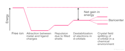
Crystal Field Splitting
The metal-ligand bond was defined as an ionic bond arising solely from electrostatic interactions between metal ions and ligands in the crystal field theory. Anions are treated as point charges in crystal field theory, while neutral molecules are treated as dipoles.
Transition metals' d orbitals are degenerate, meaning they have the same energy when they are not bound to any ligand. As they start bonding with other ligands, the d orbitals break apart and become non-degenerate due to different symmetries of the d orbitals and the inductive effect of the ligands on the electrons.
1.8.3 High Spin and Low Spin
The high spin complex is the complexion with the most unpaired electrons, while the low spin complex has the least number of unpaired electrons. With weak field ligands, high spin complexes are required because the crystal field splitting energy is low. Low spin complexes, on the other hand, have strong field ligands that induce maximum electron pairing in the collection of three t2 atomic orbitals due to large o.
High spin – Maximum number of unpaired electrons.
Low spin – Minimum number of unpaired electrons.
Example: [Co(CN)6]3- & [CoF6]3-
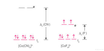
High Spin and Low Spin Complex
[Co(CN)6]3- – Low spin complex
[CoF6]3- – High spin complex
The pattern of the splitting of d orbitals depends on the nature of the crystal field. The splitting in various crystal fields is discussed below:
1.8.4 Crystal Field Splitting in Octahedral Complex
We observe repulsion between the electrons in d orbitals and ligand electrons in an octahedral coordination compound of six ligands surrounding the metal atom/ion. This repulsion is stronger in the case of dx2-y2 and dz2 orbitals, which point towards the axes along the direction of the ligand and thus have higher energy than the average energy in the spherical cryst.
The dxy, dyz, and dxz orbitals, on the other hand, have lower repulsions because they are guided between the axes.
As a result, these three orbitals have less energy than the spherical crystal field's average energy.
As a result of the repulsions in an octahedral coordination compound, two energy levels are produced:
t2g– set of three orbitals (dxy, dyz and dxz) with lower energy
eg – set of two orbitals (dx2-y2 and dz2) with higher energy
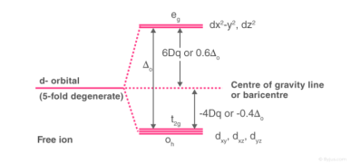
Splitting of the Crystal Field in the Octahedral Complex
Crystal field splitting is the splitting of degenerate levels in the presence of ligand. The difference in energy between t2g and eg level is denoted by the letter “o.” (subscript o stands for octahedral). Some ligands produce strong fields, resulting in large crystal field splitting, while others produce weak fields, resulting in small crystal field splitting.
1.8.5 Crystal Field Splitting in Tetrahedral Complex
The representation of two sets of orbitals as Td is the splitting of fivefold degenerate d orbitals of the metal ion into two levels in a tetrahedral crystal region. The ligands repel electrons in the dx2-y2 and dz2 orbitals less than electrons in the dxy, dyz, and dxz orbitals. As a result, the energy of the dxy, dyz, and dxz orbital sets is increased, while the energy of the dx2-y2 and dz2 orbitals is decreased.
Td complexes have only four ligands, so the total negative charge of four ligands, and therefore the ligand region, is lower than that of six ligands.
The orbitals do not point in the same direction when the ligands as they approach the metal ion.
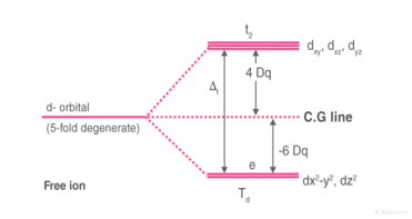
Crystal Field Splitting in Tetrahedral Complex
Thus, the repulsions in tetrahedral coordination compound yield two energy levels:
t2– set of three orbitals (dxy, dyz and dxz) with higher energy
e – set of two orbitals (dx2-y2 and dz2) with lower energy
Since there are only two-thirds as many ligands in a tetrahedral complex and the d orbitals have a less direct impact, the crystal field splitting in an octahedral complex is intrinsically smaller. e set's relative stabilising effect will be -6Dq, while t2 set's destabilising effect will be +4Dq.
1.8.6 Crystal Field Stabilization Energy
The energy levels break in a chemical system as directed by the symmetry of the local field surrounding the metal ion. The difference in energy between the eg and t2g levels is represented by or 10Dq. According to the formula, each electron that enters the lower t2g level stabilises the system by -4Dq, while the electron that enters the eg level destabilises the system by +6Dq. That is, the t2g is 4Dq lower and the eg level is +6Dq higher.
The net change in energy for d5 and d10 systems, for example, will be zero, as shown below.
d5 :- 3(-4Dq) + 2(+6Dq) = -12Dq + 12Dq = 0
d10 :- 6(-4Dq) + 4(+6Dq) = -24Dq + 24Dq = 0
The decrease in energy caused by the splitting of the energy levels is called the “Ligand Field Stabilization Energy (LFSE)”.
1.8.7 Crystal Field Stabilization Energy Table
The crystal field stabilization energies for some octahedral and tetrahedral complexes of 3d metal ions are tabulated below.
Electronic Configuration | Octahedral Complex | Tetrahedral Complex | ||
Weak Field (-Dq) | Strong Field (-Dq) | Weak Field (-Dq) | Strong Field (-Dq) | |
d0 | 0 | 0 | 0 | 0 |
d1 | 4 | 4 | 6 | 6 |
d2 | 8 | 8 | 12 | 12 |
d3 | 12 | 12 | 8 | (18)* |
d4 | 6 | 16 | 4 | (24)* |
d5 | 0 | 20 | 0 | (20)* |
d6 | 4 | 24 | 6 | (16)* |
d7 | 8 | 18 | 12 | 12 |
d8 | 12 | 12 | 8 | 8 |
d9 | 6 | 4 | 4 | 4 |
d10 | 0 | 0 | 0 | 0 |
As a result, the crystal field splitting is determined by the ligand's field and the charge on the metal ion. The spectrochemical series has been proposed as an experimentally defined series based on the absorption of light by coordination compounds with various ligands. The ligands in the spectrochemical sequence are arranged in order of field strength as follows:
I– < Br– < Cl– < SCN– < F– < OH– < C2O42- < H2O < NCS– < EDTA4- < NH3 < en < CN–< CO
The first three electrons are arranged in the t2g level according to Hund's law, and then the d-orbitals are filled. The fourth electron can either reach the t2g stage, resulting in a t2g4eg0 configuration, or the eg orbital, resulting in a t2g3eg1 configuration. This is determined by two parameters: crystal field splitting magnitude, o, and pairing energy, P. The following is a clearer explanation of the possibilities in two cases:
o > P – Electron reaches the t2g stage, resulting in a t2g4eg0 configuration. Strong field ligands produce low spin complexes and are classified as strong field ligands.
o P – Electron reaches the eg stage, resulting in a t2g3eg1 configuration. Weak field ligands are ligands that produce this configuration and form high spin complexes.
Key takeaway:
Many important properties of transition-metal complexes, including their colours, magnetism, structures, stability, and reactivity, are explained by crystal field theory, which suggests that metal–ligand interactions are only electrostatic in nature.
The stable molecules have more electrons in the lower-energy (bonding) molecular orbitals than the higher-energy (antibonding) molecular orbitals in a molecular orbital diagram. The complex's stability improves when the lower-energy range of d orbitals (the t2g orbitals) is selectively populated by electrons. The single d electron in a d1 complex like [Ti(H2O)6]3+, for example, is located in one of the t2g orbitals. As a result, this complex will be 0.4o more stable than predicted strictly electrostatically. The crystal field stabilisation energy is the additional stabilisation of a metal complex by selective population of the lower-energy d orbitals (CFSE). Multiplying the number of electrons in t2g orbitals by the energy of those orbitals (0.4o), multiplying the number of electrons in eg orbitals by the energy of those orbitals (+0.6o), and summing the two gives the CFSE of a complex. CFSE values for octahedral complexes with different d electron configurations are described in Table 23.11 "CFSEs for Octahedral Complexes with Different Electron Configurations (in Units of"). Low-spin d6 complexes have the highest CFSE, which helps to explain why there are so many Co(III) complexes identified. The other low-spin configurations, as well as the d3 configuration, have high CFSEs.
CFSEs for Octahedral Complexes with Different Electron Configurations (in Units of o) Table 23.11 CFSEs for Octahedral Complexes with Different Electron Configurations (in Units of o)
1.9.1 Crystal Field Stabilization Energies:
| High Spin | CFSE (Δo) | Low Spin | CFSE (Δo) | ||
d 0 |
|
| 0 |
|
|
|
d 1 | ↿ |
| 0.4 |
|
|
|
d 2 | ↿ ↿ |
| 0.8 |
|
|
|
d 3 | ↿ ↿ ↿ |
| 1.2 |
|
|
|
d 4 | ↿ ↿ ↿ | ↿ | 0.6 | ↿⇂ ↿ ↿ |
| 1.6 |
d 5 | ↿ ↿ ↿ | ↿ ↿ | 0.0 | ↿⇂ ↿⇂ ↿ |
| 2.0 |
d 6 | ↿⇂ ↿ ↿ | ↿ ↿ | 0.4 | ↿⇂ ↿⇂ ↿⇂ |
| 2.4 |
d 7 | ↿⇂ ↿⇂ ↿ | ↿ ↿ | 0.8 | ↿⇂ ↿⇂ ↿⇂ | ↿ | 1.8 |
d 8 | ↿⇂ ↿⇂ ↿⇂ | ↿ ↿ | 1.2 |
|
|
|
d 9 | ↿⇂ ↿⇂ ↿⇂ | ↿⇂ ↿ | 0.6 |
|
|
|
d 10 | ↿⇂ ↿⇂ ↿⇂ | ↿⇂ ↿⇂ | 0.0 |
|
|
|
The presence of CFSEs is important for two reasons. For starters, the presence of CFSE explains the discrepancy between experimentally determined bond energies in metal complexes and values calculated solely on electrostatic interactions. Second, CFSEs contain a significant amount of energy (up to several hundred kilojoules per mole), which has significant chemical implications.
Key takeaway:
Octahedral d3 and d8 complexes and low-spin d6, d5, d7, and d4 complexes exhibit large CFSEs.
1.9.2 Spectrochemical series:
Strong and weak field ligands.
The energy difference O between the t2g and eg orbitals in their octahedral complexes is used to rank ligands in the spectrochemical sequence. The spectral transformation between these stages, which is mostly in the visible part of the spectrum and is responsible for the colours of complexes with partially filled d-orbitals, is used to quantify the energy difference. Powerful field ligands produce a large splitting, while weak field ligands produce a small splitting.
An abbreviated spectrochemical series is:
Weak field I- < Br- < Cl- < NO3- < F- < OH- < H2O < Pyridine < NH3 < NO2- < CN- < CO Strong field
Orbital overlap
The antibonding interaction between the eg metal orbitals and the ligands is reflected in the splitting between d-electron levels, as seen in the molecular orbital diagram above. As a result, we anticipate that ligand field strength would be linked to metal-ligand orbital overlap. Weak field ligands bind through very electronegative atoms like O and halogens, whereas strong field ligands bind through C or P. The power of ligands that bind through N is intermediate. Hard bases are weak field ligands, whereas soft bases are strong field ligands, to put it another way.

Water is a weak ligand in the field. The electron pair on the electronegative O atom is highly electron-withdrawing, so there is no orbital overlap between it and a metal d-orbital. The strong field ligand CN- has a more electropositive C atom, which allows for greater orbital overlap and electron pair sharing. It's worth noting that the C atom, rather than the N atom, is used to coordinate metal ions in CN-.
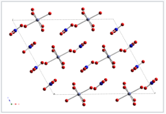
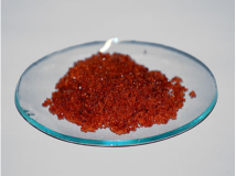
The colour of cobalt (II) complexes varies depending on the type of the ligand. Each cobalt ion is coordinated by six water molecules in crystals of the red compound cobalt(II) nitrate dihydrate. To form a salt, the [Co(H2O)6]2+ cations and NO3- anions crystallise. Co(II) maintains its coordination shell of six water molecules when dissolved in water, and the solution is the same red colour as the crystal.
Energy units
The splitting energy O can be measured in a variety of ways, and it's helpful to try to equate it to more common quantities like bond energies.
E=hv=hc=hc(5.4.1) E=hv=hc=hc(5.4.1) E=hv=hc=hc( (5.4.1)
E=h=hc=hc is the electromagnetic radiation frequency, h is Planck's constant (6.626x10⁻³⁴ J*s), and c is the speed of light. The inverse of the wavelength, typically measured in cm-1, is called the "wavenumber." Spectroscopists often express energy differences in terms of wavenumbers.
A red photon, for example, has a wavelength of 620 nm and a wavenumber of 16,000 cm-1. The same red photon has an energy of 2.0 eV (1 eV = 1240 nm) or 193 kJ/mol (1 eV = 96.5 kJ/mol) in other energy units. As compared to the dissociation energy of a single carbon-carbon bond (350 kJ/mol), the C-C bond has roughly twice the energy of a red photon. To sever a C-C bond, we'd need an ultraviolet photon (E > 350 kJ/mol = 3.6 eV = 345 nm = 29,000cm-1).
For transition metal complexes, we'll see that O varies greatly, from near-infrared to ultraviolet wavelengths. As a result, the energy difference between the t2g and eg orbitals will vary from that of a weak to a strong covalent bond.
ΔO depends on both the metal and the ligand. We can learn something about trends in ΔO by comparing a series of d6 metal complexes
Complex | ΔO (cm-1) |
[Co(H2O)6]2+ | 9,300 |
[Co(H2O)6]3+ | 18,200 |
[Co(CN)6]3- | 33,500 |
[Rh(H2O)6]3+ | 27,000 |
[Rh(CN)6]3- | 45,500 |
Important trends in ΔO:
Co3+ complexes have larger ΔO than Co2+ complexes with the same ligand. This reflects the electrostatic nature of the crystal field splitting.
Rh3+ complexes have larger ΔO than Co3+ complexes. In general, elements in the 2nd and 3rd transition series (the 4d and 5d elements) have larger splitting than those in the 3d series.
The pattern in O for a given metal in one oxidation state (e.g., Co3+) follows the spectrochemical sequence. Thus, [Co(CN)6]3-, which contains the strong field CN- ligand, has a larger O than [Co(H2O)6]3+, which contains the weak field ligand H2O.
The size and chemistry of the 4d and 5d elements are identical. We still notice 3d 4d 5d when comparing O values for complexes in the 3d, 4d, and 5d sequence (e.g., comparing elements in the triads Co,Rh,Ir or Fe,Ru,Os). This pattern represents the d-orbitals' spatial degree and thus their overlap with ligand orbitals. The 3d orbitals are smaller than the 4d and 5d orbitals, and they are less efficient at bonding. Because of the lanthanide contraction, the 4d and 5d orbitals are very close. The fourteen lanthanide elements are found at the start of the 5d sequence (between 56Ba and 72Hf) (57La - 71Lu).
The addition of 14 protons to the nucleus in crossing the lanthanide sequence contracts the sizes of the atomic orbitals, despite the fact that the valence orbitals of the 5d elements are in a higher principal quantum shell than those of the 4d elements. The important finding is that the valence orbitals of the 4d and 5d elements are identical in size, and therefore the elements in their chemistry resemble each other even more than their 3d sequence cousins. The chemistry of Ru, for example, is quite similar to that of Os, as shown below, but very different from that of Fe.
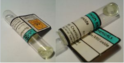
MO4 is a volatile molecular tetroxide formed by Os and Ru. OsO4 is used as a dye in electron microscopy and in epoxidation reactions. The largest binary oxide of iron, on the other hand, is Fe2O3.
Colors of transition metal complexes
Observing the colour of a transition metal complex is an easy, qualitative way to see the relative crystal field splitting energy, O. The wider the energy difference, the higher the energy of the absorbed photon. The colour a complex absorbs, on the other hand, is complementary to the colour it appears (i.e., the colour of light it reflects), which is on the colour wheel opposite the absorbed colour.
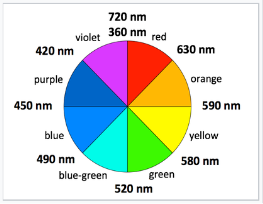
Complementary colors are across the color wheel from each other
Examples: (all d7 Co2+ complexes)
[Co(H2O)6]2+ looks purple in its salts and in concentrated solution because it absorbs in the green range.
[Co(NH3)6]2+ is straw-colored because it absorbs in the blue range.
[Co(CN)6]4-, looks red, absorbs in the violet and ultra-violet part of the spectrum.
Since the energy of a UV photon is higher than that of a red-orange photon, this supports the theory that CN- is a stronger field ligand than NH3.
The majority of transition metal complexes absorb in the visible range (400-700 nm = 25,000 to 14,300 cm-1), or have UV transitions that tail into the visible, giving them a yellow appearance; however, some complexes, such as [Rh(CN)6]3-, appear colourless because their d-d transitions are in the ultraviolet. Since their d-d transitions require a shift in the complex's spin state, other complexes, such as [Mn(H2O)]62+, are weakly coloured.
Crystal Field Theory predicts that, depending on the ligand field geometry and metal d-electron configurations, the distribution of electrons in the d orbitals can lead to net stabilisation (energy reduction) of some complexes. Calculating this stabilisation is easy because all that is needed is knowledge of the splitting patterns and the electron configuration.
1.10.1 Definition: Crystal field stabilization energy:
Stabilization of the Crystal Field The energy of the electron configuration in the ligand field is subtracted from the energy of the electronic configuration in the isotropic field to get energy.
CFSE=E=Eligand fieldEisotropic fieldCFSE=E=Eligand fieldEisotropic field
The CSFE will be determined by a number of factors, including:
An electron in the more stable t2g subset contributes 2/5o to an octahedral complex, while an electron in the higher energy eg subset contributes +3/5o to destabilisation. After that, the result is expressed as a multiple of the crystal field splitting parameter o. The term PP is used to describe the spin pairing energy when any electrons are paired within a single orbital.
Example 1: CFSE for a high Spin d7complex
What is the Crystal Field Stabilization Energy for a high spin d7d7 octahedral complex?
Solution
The electron structure and splitting pattern for isotropic and octahedral ligand fields are compared below.
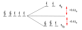
The energy of the isotropic field (Eisotropic field) is
Eisotropic field=7×0+2P=2P
The energy of the octahedral ligand field Eligand field is
Eligand field=(5×−2/5Δo)+(2×3/5Δo)+2P=−4/5Δo+2P
So via Equation 11, the CFSE is
CFSE=Eligand field−Eisotropic field=(−4/5Δo+2P)−2P=−4/5Δo
Notice that the Spin pairing Energy falls out in this case (and will when calculating the CFSE of high spin complexes) since the number of paired electrons in the ligand field is the same as that in isotropic field of the free metal ion.
Example: CFSE for a Low Spin complex
What is the Crystal Field Stabilization Energy for a low spin d7 octahedral complex?
Solution
The splitting pattern and electron configuration for both isotropic and octahedral ligand fields are compared below.

The isotropic field's energy is the same as that measured in Example 1 for the high spin configuration:
eisotropic field=70+2P=2P eisotropic field=70+2P=2P eisotropic field=
The octahedral ligand's energy) field The area of eligand is
Eligand field=(62/5o)+(13/5o)+3P=9/5o+3P Eligand field=(62/5o)+(13/5o)+3P Eligand field=(62/5o)+(13/5o)+3P Eligand field=(62/5o)+
As a result of Equation 11, the CFSE is
CFSE=Eligand fieldEisotropic field=(9/5o+3P)2P=9/5o+P CFSE=Eligand fieldEisotropic field=(9/5o+3P)2P=9/5o+P CFSE=Eligand fieldEisotropic field=(9/5o+
Due to the extra energy required to pair up one extra group of electrons, the pairing energy has been added. This tends to be a more stable configuration than the high spin d7d7 configuration in Example 11, but we must also note the Pairing energy P, which ranges from 200 to 400 kJmol1 depending on the metal.
Table: Crystal Field Stabilization Energies (CFSE) for high and low spin octahedral complexes | |||||||
Total d-electrons | Isotropic Field | Octahedral Complex | Crystal Field Stabilization Energy | ||||
|
| High Spin | Low Spin |
| |||
| Eisotropic fieldEisotropic field | Configuration | Eligand fieldEligand field | Configuration | Eligand fieldEligand field | High Spin | Low Spin |
d0 | 0 | t2gt2g0egeg0 | 0 | t2gt2g0egeg0 | 0 | 0 | 0 |
d1 | 0 | t2gt2g1egeg0 | -2/5 ΔoΔo | t2gt2g1egeg0 | -2/5 ΔoΔo | -2/5 ΔoΔo | -2/5 ΔoΔo |
d2 | 0 | t2gt2g2egeg0 | -4/5 ΔoΔo | t2gt2g2egeg0 | -4/5 ΔoΔo | -4/5 ΔoΔo | -4/5 ΔoΔo |
d3 | 0 | t2gt2g3egeg0 | -6/5 ΔoΔo | t2gt2g3egeg0 | -6/5 ΔoΔo | -6/5 ΔoΔo | -6/5 ΔoΔo |
d4 | 0 | t2gt2g3egeg1 | -3/5 ΔoΔo | t2gt2g4egeg0 | -8/5 ΔoΔo + P | -3/5 ΔoΔo | -8/5 ΔoΔo + P |
d5 | 0 | t2gt2g3egeg2 | 0 ΔoΔo | t2gt2g5egeg0 | -10/5 ΔoΔo + 2P | 0 ΔoΔo | -10/5 ΔoΔo + 2P |
d6 | P | t2gt2g4egeg2 | -2/5 ΔoΔo + P | t2gt2g6egeg0 | -12/5 ΔoΔo + 3P | -2/5 ΔoΔo | -12/5 ΔoΔo + P |
d7 | 2P | t2gt2g5egeg2 | -4/5 ΔoΔo + 2P | t2gt2g6egeg1 | -9/5 ΔoΔo + 3P | -4/5 ΔoΔo | -9/5 ΔoΔo + P |
d8 | 3P | t2gt2g6egeg2 | -6/5 ΔoΔo + 3P | t2gt2g6egeg2 | -6/5 ΔoΔo + 3P | -6/5 ΔoΔo | -6/5 ΔoΔo |
d9 | 4P | t2gt2g6egeg3 | -3/5 ΔoΔo + 4P | t2gt2g6egeg3 | -3/5 ΔoΔo + 4P | -3/5 ΔoΔo | -3/5 ΔoΔo |
d10 | 5P | t2gt2g6egeg4 | 0 ΔoΔo + 5P | t2gt2g6egeg4 | 0 ΔoΔo + 5P | 0 | 0 |
The spin pairing energy, or PP, is the amount of energy needed to pair electrons in the same orbital. P (pairing energy) is constant for a given metal ion, but it does not vary with ligand or metal ion oxidation state).
1.10.2 Octahedral Preference
When the d-orbital splitting is understood and the electron configuration inside those orbitals is known, similar CFSE values can be constructed for non-octahedral ligand field geometries, such as the tetrahedral complexes in Table 2. The thermodynamic tendency (Enthalpy-wise) for a metal-ligand combination to favour the octahedral geometry can then be calculated by comparing these energies geometries to the octahedral CFSE. The Octahedral Site Preference Energy, as described below, is used to quantify this.
Definition: Octahedral site preference energy:
The difference between the CFSE energies of a non-octahedral complex and the octahedral complex is known as the Octahedral Site Preference Energy (OSPE). The OSPE is OSPE=CFSE(oct)CFSE(tet) for comparing the preference for forming an octahedral ligand field vs. a tetrahedral ligand field (2)
The OSPE is a measurement of a complex's preference for octahedral over tetrahedral geometry.
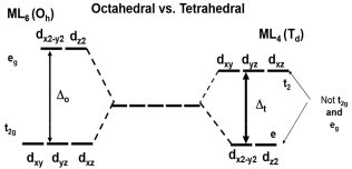
Note: the conversion between Δo and Δt used for these calculations is:
Δt≈49Δo(3)
which is applicable for comparing octahedral and tetrahedral complexes that involve same ligands only.
Table: Octahedral Site Preference Energies (OSPE) | |||||
Total d-electrons | CFSE(Octahedral) | CFSE(Tetrahedral) | OSPE (for high spin complexes)** | ||
| High Spin | Low Spin | Configuration | Always High Spin* |
|
d0 | 0 ΔoΔo | 0 ΔoΔo | e0 | 0 ΔtΔt | 0 ΔoΔo |
d1 | -2/5 ΔoΔo | -2/5 ΔoΔo | e1 | -3/5 ΔtΔt | -6/45 ΔoΔo |
d2 | -4/5 ΔoΔo | -4/5 ΔoΔo | e2 | -6/5 ΔtΔt | -12/45 ΔoΔo |
d3 | -6/5 ΔoΔo | -6/5 ΔoΔo | e2t21 | -4/5 ΔtΔt | -38/45 ΔoΔo |
d4 | -3/5 ΔoΔo | -8/5 ΔoΔo + P | e2t22 | -2/5 ΔtΔt | -19/45 ΔoΔo |
d5 | 0 ΔoΔo | -10/5 ΔoΔo + 2P | e2t23 | 0 ΔtΔt | 0 ΔoΔo |
d6 | -2/5 ΔoΔo | -12/5 ΔoΔo + P | e3t23 | -3/5 ΔtΔt | -6/45 ΔoΔo |
d7 | -4/5 ΔoΔo | -9/5 ΔoΔo + P | e4t23 | -6/5 ΔtΔt | -12/45 ΔoΔo |
d8 | -6/5 ΔoΔo | -6/5 ΔoΔo | e4t24 | -4/5 ΔtΔt | -38/45 ΔoΔo |
d9 | -3/5 ΔoΔo | -3/5 ΔoΔo | e4t25 | -2/5 ΔtΔt | -19/45 ΔoΔo |
d10 | 0 | 0 | e4t26 | 0 ΔtΔt | 0 ΔoΔo |
The spin pairing energy, or PP, is the amount of energy needed to pair electrons in the same orbital.
Since the splitting in tetrahedral complexes is much smaller than in PP, they are still high spin (Equation 33).
Equation 33 was used to convert the data. The curves in Figure 11 below graphically show the data in Tables 11 and 22 for the high spin complexes only. The graphing of low spin complexes necessitates PP information.

Figure: Crystal Field Stabilization Energies for Octahedral and Tetrahedral Fields. The OSPE (Octahedral Site Preference Energies) are shown in purple. This is for complexes with a lot of spin.
The following conclusions can be drawn from a cursory review of Figure 11:
In the d1d1, d2d2, d5d5, d6d6, and d7d7 complexes, the OSPE is weak, and other factors, such as steric factors, affect the stability of the complexes.
In d3d3 and d8d8 complexes, the OSPE is high, favouring octahedral geometries.
1.10.3 Applications
The "double-humped" curve in Figure 11 is observed for a variety of properties of the first-row transition metals, including M(II) ionic hydration and lattice energies, ionic radii, and M(II) complex stability. This indicates that these characteristics are linked to Crystal Field effects in some way.
M2+(g)+H2O[M(OH2)6]2+ M2+(g)+H2O[M(OH2)6]2+ M2+(g)+H2O[M(OH2)6]2+ M2+(g)+H2O[M(OH2)6]2+ M2+(g)+H2O[M(OH2)6]2+ M2+(g)+H2O (aq)
This form of curve can be seen in Table 3 and Figure 1. Since a number of ions are not very stable in the M(II) state, not all of the data in any sequence of this kind is available.
Table: Hydration energies of M2+M2+ ions | |||
M | ΔH°/kJmol-1 | M | ΔH°/kJmol-1 |
Ca | -2469 | Fe | -2840 |
Sc | no stable 2+ ion | Co | -2910 |
Ti | -2729 | Ni | -2993 |
>V | -2777 | Cu | -2996 |
Cr | -2792 | Zn | -2928 |
Mn | -2733 |
|
|
Graphically the data in Table 2 can be represented by:
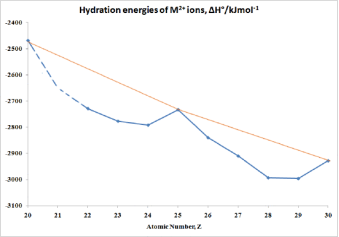
Figure: hydration energies of M2+M2+ ions
What criteria do we use to determine whether a complex is octahedral, tetrahedral, or square planar? If we know the formula, we can make an educated guess: anything of the kind ML6 will almost always be octahedral (there is an alternative geometry for 6-coordinate complexes called trigonal prismatic, but it's pretty rare), while something of the formula ML4 will almost always be tetrahedral (unless the metal atom has the d8 electron configuration, in which case it will probably be square plana). But what if we combine a certain metal ion with a specific ligand? Is it possible to predict whether it would form an octahedral or tetrahedral complex, for instance? Yeah, to some degree... we can definitely tell what factors would promote the creation of tetrahedral complexes rather than the more common octahedral complexes.
In comparison to the energy of the initial five degenerate d orbitals, the Crystal Field Stabilization Energy (CFSE) is the additional stabilisation obtained by separating the orbitals according to crystal field theory. Putting an electron into one of the t2g level's orbitals, for example, gains -0.4 o of CFSE in a d1 situation like [Ti(OH2)6]3+. In general, octahedral complexes would be preferred over tetrahedral complexes because: forming six bonds rather than four is more (energetically) desirable.
The CFSE of octahedral complexes is normally higher than that of tetrahedral complexes. Keep in mind that o is larger than tet (tet is roughly 4/9 o).
We can measure the difference in stabilisation energy between octahedral and tetrahedral geometries by referencing everything in terms of o if we assume tet = 4/9 o.
d3 stabilised structure (example 1)
Which is the preferred d3 metal configuration: tetrahedral or octahedral?
Solution
To address this, the Crystal Field Stabilization Energy for a (d3(d3 metal in both configurations must be determined. The preferred geometry would be the one with the most stabilisation.
The Crystal Field Stabilization Energy for a d3 octahedral configuration is 30.4o=1.2o
The Crystal Field Stabilization Energy for a d3 tetrahedral configuration (assuming high spin)
Tetrahedral complexes are often high spin since tet is less than half the size of o. We can now express this in terms of o (we can do so because we're dealing with the same metal ion and ligand; the only difference is the geometry).
The Crystal Field Stabilization Energy for tetrahedral d3 is:
CFSE = -0.8 x 4/9 o = -0.355 o CFSE = -0.8 x 4/9 o CFSE = -0.8 x 4/9 o CFSE = -
The Crystal Field Stabilization Energy difference between the two geometries would be:
0.845 o = 1.2 - 0.355 o.
We can make a Table of o, tet, and the difference between them if we do the same calculation for the other configurations .
Table: Crystal Field Stabilization Energies (not splitting parameters). This table compares the values of the CFSE for octahedral and tetrahedral geometries, assuming high spin configurations. The units are Δo, and we're assuming that Δtet = 4/9 Δo. | |||
| Octahedral | Tetrahedral | Difference |
d0, d5, d10 | 0 | 0 | 0 |
d1, d6 | 0.4 | 0.27 | 0.13 |
d2, d7 | 0.8 | 0.53 | 0.27 |
d3, d8 | 1.2 | 0.36 | 0.84 |
d4, d9 | 0.6 | 0.18 | 0.42 |
These values can be plotted:
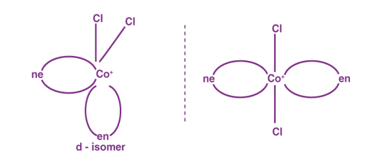
Figure: Crystal Field Stabilization Energy as a function of d-electrons for a hypothetical molecule in the octahedral (green curve) and tetrahedral (blue curve) geometries. (CC BY-NC; Ümit Kaya)
In most cases, the Crystal Field Stabilization Energy prefers octahedral to tetrahedral, but the degree of favorability varies depending on the electronic configuration. In other words, there is a slight gap between the oct and tet lines for d1, but a large gap for d3 and d8. However, there is no CFSE discrepancy between octahedral and tetrahedral for d0, d5 high spin, and d10. d3, d8 > d4, d9> d2, d7 > d1, d6 > d0, d5, d10> d2, d7 > d1, d6 > d0, d5, d10> d2, d7 > d1, d6 > d0, d5, d10> d2, d7 > d1, d6 > d0, d5, d10
The graph's units are o's. As a result, if strong field ligands are present, o will be larger (according to the spectrochemical series), and any energy difference between the oct and tet lines will be amplified. A larger o may also move the complexes to low spin. High oxidation states and metals from the 2nd and 3rd rows of the transition sequence will also drive up o, as we saw previously.
Large or highly charged ligands, on the other hand, can experience large interligand repulsions and thus prefer a lower coordination number (4 instead of 6). As a result, if you wanted to make something with a tetrahedral geometry, you'd use big, negatively charged weak field ligands and a metal atom from the first row of the transition sequence (though weak field ligands aren't necessary in these three configurations because the difference between oct and tet is 0 o). Table 2 shows that tetrahedral complexes exist for most configurations, but only a few exist for d3 and d8.
Table: Tetrahedral complexes of different d electron counts | |||
d0 | MnO4- | d5 | MnCl42- |
d1 | TiCl4- | d6 | FeCl42- |
d2 | Cr(OR)4 | d7 | CoCl42- |
The attraction between the positively charged metal cation and the negative charge on the non-bonding electrons of the ligand causes the interaction between a transition metal and ligands, according to crystal field theory. The theory is built around the energy changes that occur when the five degenerate d-orbitals are surrounded by an array of point charges made up of ligands. The electrons from the ligand would be closer to some of the d-orbitals and further away from others as the ligand reaches the metal ion, resulting in a lack of degeneracy. Due to repulsion between like charges, the electrons in the d-orbitals and those in the ligand repel each other. As a result, the d-electrons closest to the ligands would have a higher energy than those farther out, dividing the energy of the d-orbitals. The structure of the metal ion, as well as the metal's oxidation state, have an effect on this splitting. In comparison to the spherical region, a higher oxidation state causes further splitting.
The ligands' structure around the metal ion.
The metal's coordination number is (i.e. tetrahedral, octahedral...)
the ligands that surround the metal ion's nature The greater the difference between the high and low energy d groups, the stronger the effect of the ligands.
The octahedral complex is the most common kind, with six ligands forming the vertices of an octahedron around the metal ion. The d-orbitals in octahedral symmetry split into two sets with an energy difference, oct (the crystal-field splitting parameter, also commonly denoted by 10Dq for ten times the "differential of quanta"), where the dxy, dxz, and dyz orbitals will have lower energy than the dz2 and dx2-y2 orbitals, which will have higher energy, because the former is farther from The three lower-energy orbitals are known as t2g, and the two higher-energy orbitals are known as eg. These names are irreducible representations of the octahedral point group, Oh, and are based on the theory of molecular symmetry. (See the Oh character table for more information.) In the section High-spin and low-spin, you'll find typical orbital energy diagrams.
The second most common category is tetrahedral complexes, which have four ligands forming a tetrahedron around the metal ion. The d-orbitals break into two groups with an energy difference of tet in a tetrahedral crystal field splitting. In contrast to the octahedral case, the lower energy orbitals will be dz2 and dx2-y2, while the higher energy orbitals will be dxy, dxz, and dyz. Furthermore, the energy splitting would be lower in tetrahedral symmetry than in octahedral symmetry because the ligand electrons are not directed directly towards the d-orbitals. CFT may also define square planar and other complex geometries.
The size of the distance between two or more sets of orbitals is determined by number of variables, including the ligands and complex geometry. Certain ligands often produce a low value of, whereas others always produce a high value of. The ligand field theory may explain why this is the case. The spectrochemical sequence is a list of ligands ordered by the size of the splitting they emit (from small to large; see also this table):
I− < Br− < S2− < SCN− (S–bonded) < Cl− < NO3− < N3− < F− < OH− < C2O42− < H2O < NCS− (N–bonded) < CH3CN < py < NH3 < en < 2,2'-bipyridine < phen < NO2− < PPh3 < CN− < CO.
It's worth noting that the ligands that can participate in metal to ligand back-bonding produce the most splitting.
The size of the gap between the high and low energy levels is also influenced by the metal's oxidation state. The magnitude of increases as the oxidation state of a metal increases. For a given set of ligands, a V3+ complex would have a greater than a V2+ complex since the charge density difference causes the ligands to be closer to a V3+ ion than a V2+ ion. Since the ligand and metal electrons are closer together and repel more, a smaller distance between the ligand and the metal ion results in a larger.
1.12.1 Introduction
According to the radius ratio, the larger the charge on the central ion, the more attraction there would be for negatively charged ligands; moreover, the larger the charge, the smaller the ion becomes, limiting the number of groups that can cooperate. It's important to remember that every geometry has a unique coordination number, but every complex with a unique coordination number has a variety of geometries to choose from (i.e., there is not a one-to-one correspondance between coordination number and geometry).
1.12.2 Coordination Number 2
For first row transition metal ion complexes, this arrangement is not very popular, although some of the best known examples are for Silver (I). In this case, the d-block has a low charge and an ion on the right hand side, suggesting a smaller scale.
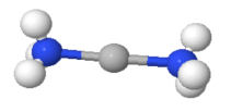
Figure: The linear [Ag(NH3)2]+ ion
1.12.3 Coordination Number 3
This isn't very popular for first-row transition metal ions, once again. Three different geometries have been listed as examples:

Trigonal planar Geometry: This geometry, which is well known for main group species such as CO32-, has the four atoms in a plane with the bond angles between the ligands at 120 degrees.
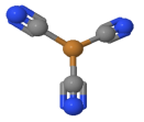
Figure: The Trigonal planar [Cu(CN)3]2- system
Trigonal pyramid Geometry: More common with main group ions.
T-shaped: The first example of a rare T-shaped molecule was found in 1977.
1.12.4 Coordination Number 4
There are two different geometries that can be used. The tetrahedron is more common, while the square planar is almost always associated with metal ions with a d8 electronic configuration.
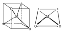
Tetrahedral Geometry: Organic courses cover the chemistry of molecules based on a tetrahedral C atom. Please change all instances of C to Co to be politically correct. There are a lot of tetrahedral Cobalt(II) complexes out there.
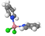
Figure: CoCl2pyr2
Square Planar Geometry: This is a fairly uncommon shape that is only used because certain highly significant molecules have this shape.
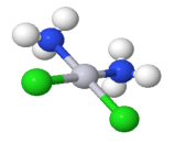
Figure: cisplatin - cis-PtCl2(NH3)2
1.12.5 Coordination Number 5

Square pyramid Geometry: Oxovanadium salts (Vanadyl, VO2+), such as VO(acac)2, have a square pyramidal geometry. It's worth noting that Vanadium(IV) is coordinatively unsaturated, and adding pyridine results in the formation of an octahedral complex.
Trigonal Bipyramid Geometry: In 1968, it was stated that the structure of [Cr(en)3][Ni(CN)5] 1.5 H2O was a remarkable example of a complex exhibiting both forms of geometry in the same crystal. Several phases are involved in the cyanide ion's reaction with Ni2+:
Ni2++2CN−→Ni(CN)2…….(1)
Ni(CN)2+2CN−→[Ni(CN)4]2−orange-red……….(2)
with log(β4)=30.1
[Ni(CN)4]2−+CN−→[Ni(CN)5]3−deep red…….(3)
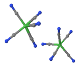
Figure: [Ni(CN)5]3-
1.12.6 Coordination Number 6

Hexagonal planar Geometry: While the arrangement of six groups in a plane is seen in some higher coordination number geometries, it is unknown for first row transition metal ions.
Trigonal prism Geometry : Most trigonal prismatic compounds, such as dithiolates or oxalates, have three bidentate ligands, and only a few are classified for first row transition metal ions.
Octahedral (Oh): The most popular geometry for transition metal ions in the first row, including all aqua ions. In some cases, distortions are found, which can be explained using the Jahn-Teller Theorem in some cases.
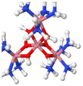
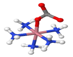
Figure: [Co(en)3]Cl3(left) and [CoCO3(NH3)5]+ (right)
1.12.7 Coordination Number 7
It's not very normal for 1st row complexes, and the energy difference between the structures appears to be slight, and distortions occur, making it difficult to predict the closest "idealised" form. There are three possible geometries:

Capped octahedron (C3v) Geometry
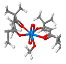
Figure: K3[NbOF6]
Capped trigonal prism (C2v)
Pentagonal Bipyramid (D5h)
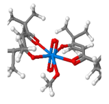
Figure: bis-(tert-butylacac)2(DMSO)di-oxoUranium
1.12.8 Coordination Number 8

Dodecahedron (D2d) Geometry
Cube (Oh) Geometry
Square antiprism (D4d) Geometry
Hexagonal bipyramid (D6h) Geometry
1.12.9 Coordination Number 9
Three-face centered trigonal prism (D3h) Geometry
1.12.10 Coordination Number 10
Bicapped square antiprism (D4d) Geometry
1.12.11 Coordination Number 11
All-faced capped trigonal prism (D3h) Geometry: This is not a common stereochemistry.
Figure: aqua-(12-crown-4)-tris(nitrato-O,O')-cerium(III) (12-crown-4) solvate and (15-crown-5)-tris(nitrato-O,O')-cerium(III) the Cerium ion is 11 coordinate.
Coordination Number 12
Cuboctahedron (Oh) Geometry
Figure: Ceric ammonium nitrate -(NH4)2Ce(NO3)6
1.13.1 Introduction
In terms of its electronic state, Hermann Jahn and Edward Teller proposed a theorem in 1937 stating that "stability and degeneracy are not possible simultaneously unless the molecule is a linear one." This causes a degeneracy break, which stabilises the molecule and, as a result, decreases its symmetry. Since 1937, the theorem has been revised to "any non-linear molecular system in a degenerate electronic state will be unstable and will undergo distortion to form a system of lower symmetry and lower energy, thus eliminating the degeneracy," as Housecroft and Sharpe put it. This occurs most often in transition metal octahedral complexes, but it can also occur in tetrahedral compounds.
When constructing a molecular orbital diagram for a given octahedral complex, the five d atomic orbitals are split into two degenerate groups. The symmetry codes for these sets are t2g (dxz, dyz, dxy) and eg (dz2 and dx2y2). When a molecule's electronic ground state is degenerate, it can distort to eliminate the degeneracy and form a lower energy (and, as a result, lower symmetry) system. As shown in Figure 1, the octahedral complex can either elongate or compress the z ligand bonds:
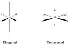
Figure: Jahn-Teller distortions for an octahedral complex.
The axial bonds of an octahedral complex are longer than the equatorial bonds as it experiences elongation. In the case of compression, the equatorial bonds are longer than the axial bonds. The amount of overlap between the metal and ligand orbitals determines the elongation and compression effects. As a result, the distortion varies greatly depending on the metal and ligands used. In general, the stronger the metal-ligand orbital interactions are, the more likely a Jahn-Teller effect may appear.
1.13.2 Elongation
When the degeneracy is broken by the stabilisation (lowering in energy) of the d orbitals with a z component, while the orbitals without a z component are destabilised (higher in energy), elongation Jahn-Teller distortions occur, as shown in Figure 2 below:
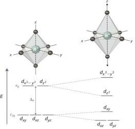
Figure: Illustration of tetragonal distortion (elongation) for an octahedral complex.
This is due to the fact that the dxy and dx2y2 orbitals overlap more with the ligand orbitals, resulting in higher energy orbitals. Since the dx2y2 orbital is antibonding, elongation is expected to increase its capacity. The dxy orbital is still nonbonding, but the interactions have destabilised it. For copper(II) octahedral compounds, Jahn-Teller elongations are well-documented. Copper(II) fluoride is a classic example, as shown in Figure 3.
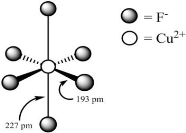
Figure: Structure of octahedral copper(II) fluoride.
The two axial bonds are both elongated, while the four shorter equatorial bonds are all the same length. Based on the model shown in Figure 2, the theorem states that distortion eliminates orbital degeneracy, making the molecule more stable.
1.13.3 Compression
When the degeneracy is broken by the stabilisation (lowering in energy) of the d orbitals without a z component, while the orbitals with a z component are destabilised (higher in energy), compression Jahn-Teller distortions occur, as shown in Figure 4 below:
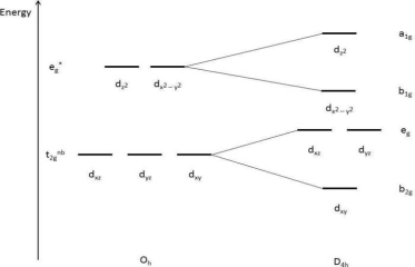
Figure: A tetragonal distortion (compression) of an octahedral complex is depicted.
This is due to the fact that the z-component d orbitals overlap more with the ligand orbitals, resulting in higher energy orbitals. Since the dz2 orbital is antibonding, compression is supposed to increase its energy. The dxz and dyz orbitals are still nonbonding, but the interactions have destabilised them.
1.13.4 Electronic Configurations
In transition metals, degeneracy in either the t2g or eg orbitals is needed for Jahn-Teller effects to occur. The number of d-electrons and the splitting energy determine the electronic states of octahedral complexes. Electrons pair in t2g before occupying eg when is large and greater than the energy needed to pair electrons. When Delta is small and less than the pairing energy, however, electrons will occupy eg before pairing in t2g. The chemical environment (ligand identification) and the identity and charge of the metal ion determine the of an octahedral complex. If the number of paired electrons in a given d-electron count varies, the configuration with the most paired electrons is called low spin, while the one with the most unpaired electrons is called high spin.
The figures below show electron configuration diagrams for d1 through d10 with large and small electrons. No matter what the magnitude of, the electron configurations for d1, d2, d3, d8, d9, and d10 are the same. Only the electron counts d4, d5, d6, and d7 have low and high spin configurations.
Large Δ
Figure (below) shows the various electronic configurations for octahedral complexes with large ΔΔ, including the low-spin configurations of d4, d5, d6, and d7:
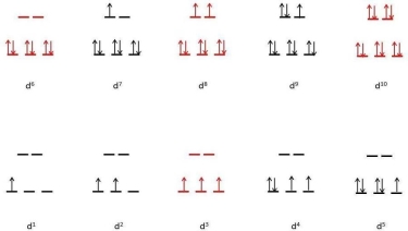
Figure: Octahedral dynamic electron structure diagram (red indicates no degeneracies possible, thus no Jahn-Teller effects).
The electron configurations in the case of large are depicted in the diagram. There are no Jahn-Teller distortions in the electron configurations illustrated in red (d3, low spin d6, d8, and d10). On the other hand, Jhan-Teller distortion is predicted in d1, d2, low spin d4, low spin d5, low spin d7, and d9. Transition metals are represented by these electronic configurations. Cr3+, Co3+, and Ni2+ are only a few examples.
Small Δ
Figure (below) shows the various electronic configurations for octahedral complexes with small Δ, including the high-spin configurations of d4, d5, d6, and d7:
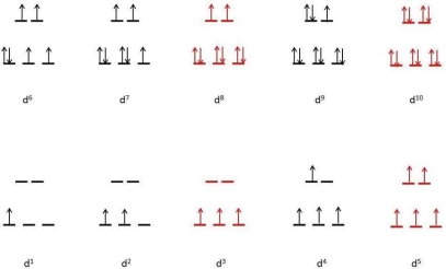
Figure: Octahedral coordination diagram with high spin (red indicates no degeneracies possible, thus no Jahn-Teller effects).
The electron configurations in the case of small are depicted in the diagram. There are no Jahn-Teller distortions in the electron configurations illustrated in red (d3, high spin d5, d8, and d10). Jahn-Teller effects are stronger in degenerate electronic states that occupy the eg orbital set. The occupation of these high-energy orbitals is the primary cause of this. The degeneracy of the eg set is broken, the symmetry is diminished, and occupations at lower energy orbitals occur because the structure is more stable with a lower energy configuration.
1.13.5 Spectroscopic Observation
A variety of spectroscopic techniques can be used to detect Jahn-Teller distortions. Due to a decrease of symmetry in UV-VIS absorption spectroscopy, distortion induces band splitting in the spectrum (Oh to D4h). Consider the case of a hypothetical molecule with octahedral symmetry and just one absorption band. The number of bands would increase if the molecule underwent Jahn-Teller distortion, as shown in Figure 7 below:
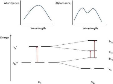
Figure: Absorption spectra of an octahedral molecule (left) and the same molecule with Jahn-Teller elongation (right) (right). Electronic transitions are shown by red arrows.
Infrared and Raman vibrational spectroscopy show a related phenomenon. The 3n - 6 rule (or 3n - 5 for linear geometry) can be used to measure the number of vibrational modes for a molecule. In comparison to a Jahn-Teller skewed molecule with D4h symmetry, a molecule with an Oh symmetry point group would have less bands. Thus, Jahn-Teller effects may be observed using either IR or Raman techniques. This effect can also be seen in EPR experiments if at least one unpaired electron is present.
Table: Examples of Jahn-Teller distorted complexes | |
CuBr2 | 4 Br at 240 pm 2 Br at 318 pm |
CuCl2 | 4 Cl at 230 pm 2 Cl at 295 pm |
CuCl 2.2H 2O | 2 O at 193 pm 2 Cl at 228 pm 2 Cl at 295 pm |
CsCuCl3 | 4 Cl at 230 pm 2 Cl at 265 pm |
CuF2 | 4 F at 193 pm 2 F at 227 pm |
CuSO4.4NH3.H2O | 4 N at 205 pm 1 O at 259 pm 1 O at 337 pm |
K2CuF4 | 4 F at 191 pm 2 F at 237 pm |
KCuAlF6 | 2 F at 188 pm 4 F at 220 pm |
CrF2 | 4 F at 200 pm 2 F at 243 pm |
KCrF3 | 4 F at 214 pm 2 F at 200 pm |
MnF3 | 2 F at 209 pm 2 F at 191 pm 2 F at 179 pm |
The Jahn-Teller Theorem predicts that distortions can occur in any degenerate state, including degeneracy at the t2g stage, but bond length distortions are even more noticeable when the degenerate electrons are at the eg level.
Square Planar Complexes
Square planar geometry is another famous geometry. A square planar geometry can be modelled as an octahedral structure with a pair of trans ligands removed. The ligands that have been removed are thought to be on the z-axis. This alters the d orbital distribution, making orbitals on or near the z-axis more stable while orbitals on or near the x- or y-axes become less stable. The octahedral t2g and eg sets break as a result, resulting in a more complicated splitting pattern (Figure 2).
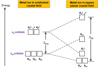
Figure. In a square planar crystal region, the t2g set and the eg set of orbitals are split. Square planar complexes, or sp, have a higher crystal field splitting energy than oct.
In another way:
A central atom is surrounded by constituent atoms that form the corners of a square on the same plane in square planar molecular geometry. Transition metal complexes with a d8 configuration are prone to this geometry. Rh(I), Ir(I), Pd(II), Pt(II), and Au are examples of this (III). Cisplatin (PtCl2(NH3)2) and other anticancer drugs are notable examples.
The coordination number of a square planar complex is also four. The ligands form a simple square on the x and y axes, which distinguishes the complex from a tetrahedral structure. The crystal field splitting is also different as a result of this (Figure 1). The repulsion of electrons in the dxz, dyz, and dz2 orbitals is significantly lower in a square planar complex than in an octahedral complex since there are no ligands along the z-axis (the dz2dz2 orbital is slightly higher in energy to the "doughnut" that lies on the x,y axis). The most energy is in the dx2y2 orbital, which is followed by the dxy orbital, which is followed by the remaining orbtails (although dz2 has slightly more energy than the dxz and dyz orbital). Throughout all geometries, this pattern of orbital splitting remains constant. Orbitals that come into direct contact with the ligand fields have higher energies than orbitals that slide past the ligand field and have more indirect contact. So, if you're not sure which geometry leads to which splitting, consider how the ligand fields interact with the central atom's electron orbitals.
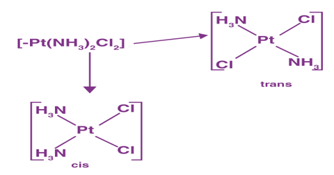
Figure: Even with a weak-field ligand, will almost always be high in square planar complexes. Since paring energy is typically much less than, electrons are more likely to be paired than unpaired. As a result, square planar complexes have a low spin. (Ümit Kaya; CC BY-SA)
Even with a weak-field ligand, will almost always be high in square planar complexes (Figure 1). Since paring energy is typically much less than, electrons are more likely to be paired than unpaired. As a result, square planar complexes have a low spin.
1.15.1 Ligand field theory:
Ligand Field Theory can be thought of as an extension of Crystal Field Theory in that it can account for all levels of covalent interactions. In certain cases, Molecular Orbital Theory is used to treat bonding in LFT. The following three diagrams show a qualitative approach that can be used for octahedral metal complexes.
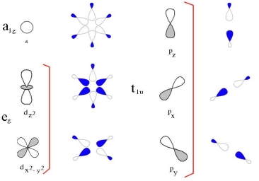
The 3d, 4s, and 4p metal ion atomic orbitals are seen in the first diagram, along with the ligand group orbitals that would have the right symmetry to overlap with them. The symmetry adapted linear comination of ligand orbitals is created by combining 6 sigma orbitals from the ligands designated as x, -x, y, -y, z, -z to form 6 ligand group orbitals.
(labelled eg, a1g, t1u)
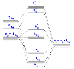
Only sigma bonding is seen in the second diagram, which depicts the combination of metal 3d, 4s, and 4p orbitals with OCCUPIED ligand group orbitals (using 1 orbital from each ligand). The metal electrons will then be fed into the t2g and eg* molecular orbitals, similar to the CFT model except that the eg orbital is now eg*.
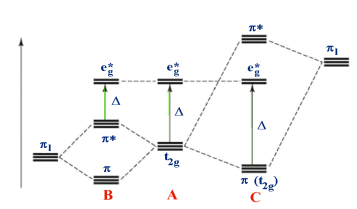
Consider the following scenario: [M(II)I6] - [M(II)I6] - [M(II)I6] 4- A - [M(II)(H2O)6] [M(II)(H2O)6] [M(II)(H2O) [M(II)(CN)6] 2+ C 4- (pi) bonding is considered in the third diagram. Bonds are weaker in general than (sigma) bonds, so the effect is to adjust rather than drastically change the definition. Two orbitals from each ligand are added together to make a total of 12, which is then split into four groups, each with three ligand group orbitals. These are designated by the letters t1g, t1u, t2g, and t2u. In both of the cases above, the metal t2g orbital is the most suitable for interaction.
Case A is the same as Case B, but without the interactions.
The ligand orbitals in case B are absolute and have a lower energy than the metal t2g. The scale of shrinks as a result of this.
The ligand orbitals in case C are empty and have a higher energy than the metal t2g. The size of grows as a result of this.
In terms of correctly placing ligands in the Spectrochemical sequence, halides are examples of case A, while groups such as CN- and CO are examples of case B. When covalent effects are taken into account, the Spectrochemical sequence can be explained.
A analysis of the IR spectra obtained for simple carbonyl compounds, such as M(CO)6, provides some compelling arguments for covalency and effects on.
The CO molecule has a tight triple bond, which results in a strong absorption at 2140 cm-1 in the infrared. The IR bands for the CO have moved to 2090, 2000, and 1860 cm-1 for the isoelectronic sequence [Mn(CO)6]+, [Cr(CO)6], and [V(CO)6]-, respectively. Despite Despite the fact that all metals have the same number of electrons (isoelectronic), the strength of the CO bond's frequency of force constant varies from Mn+ to Cr to V-.
This cannot be clarified on an ionic basis, but it is compatible with the bonding scheme since the higher the positive charge on the metal, the more difficult it is for electrons to delocalize back into the CO group's * orbitals.
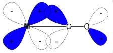
It's worth noting that the IR values we're dealing with are for the CO bond, not the M-C, because as the CO frequency decreases, the triple bond loses its character and becomes more like a double bond. If electrons are forced back from the metal into what were previously empty * antibonding orbitals, this is to be predicted.
1.15.2 Molecular orbital theory:
What is Molecular Orbital Theory?
The Molecular Orbital Theory (often abbreviated to MOT) is a chemical bonding theory formulated by F. Hund and R. S. Mulliken at the turn of the twentieth century to explain the structure and properties of various molecules. The valence-bond theory failed to sufficiently understand how many molecules, such as resonance-stabilized molecules, contain two or more identical bonds whose bond orders lie between those of a single bond and those of a double bond. The molecular orbital theory was found to be more strong than the valence-bond theory in this case (since the orbitals described by the MOT reflect the geometries of the molecules to which it is applied).
The molecular orbital theory's main features are described below.
The total number of molecular orbitals produced equals the total number of atomic orbitals given by the bonding species.
Bonding molecular orbitals, anti-bonding molecular orbitals, and non-bonding molecular orbitals are the three types of molecular orbitals. Anti-bonding molecular orbitals will always have more energy than the parent orbitals, while bonding molecular orbitals will always have less energy.
In order of increasing orbital energy, electrons are filled into molecular orbitals (from the orbital with the lowest energy to the orbital with the highest energy).
When the combining atomic orbitals have identical energies, the most powerful combinations of atomic orbitals (for the creation of molecular orbitals) occur.
The molecular orbital theory notes, in simple terms, that each atom appears to combine and form molecular orbitals. Electrons are present in various atomic orbitals as a result of this arrangement, and they are normally associated with different nuclei. In a molecule, an electron can be found anywhere in the molecule.
One of the most significant effects of the molecular orbital theory since its formulation was that it opened up new avenues for understanding the bonding mechanism. According to this theory, molecular orbitals are essentially linear combinations of atomic orbitals. The Schrödinger equation is further approximated using the Hartree–Fock (HF) or density functional theory (DFT) models
The molecular orbitals can be approximated as linear combinations of atomic orbitals using the molecular orbital theory.
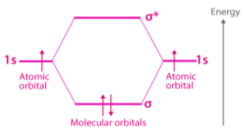
However, in order to comprehend the molecular orbital theory more simply and thoroughly, it is necessary to first comprehend what atomic and molecular orbitals
Linear Combination of Atomic Orbitals (LCAO)
A linear combination of atomic orbitals may be used to express molecular orbitals (abbreviated to LCAO). The formation of these orbitals in the bonding between the atoms that make up a molecule can be estimated using these LCAOs.
The electron behaviour of molecular orbitals can be defined using a Schrodinger equation similar to that used for atomic orbitals.
It is a method for describing molecular orbitals that is approximate. It's more like a superimposition process, in which positive interference of two atomic wave functions results in a bonding molecular orbital and destructive interference results in a non-bonding molecular orbital.
Conditions for Linear Combination of Atomic Orbitals
The following are the requirements for the linear combination of atomic orbitals:
Same Energy of Combining Orbitals
The energies of the atomic orbitals that combine to form molecular orbitals should be comparable. This means that an atom's 2p orbital will combine with another atom's 2p orbital, but 1s and 2p cannot because they have a significant energy gap.
The Molecular Axis has the same symmetry.
For proper mixing, the combining atoms must have the same symmetry around the molecular axis; otherwise, the electron density would be sparse. For example, even though all sub-orbitals of 2p have the same energy, an atom's 2pz orbital can only combine with another atom's 2pz orbital; it cannot combine with 2px and 2py orbitals because they have a different axis of symmetry. The z-axis is often referred to as the molecular axis of symmetry.
Proper Overlap between Atomic Orbitals
If the overlap is right, the two atomic orbitals will merge to form a molecular orbital. The nuclear density between the nuclei of the two atoms would be higher if their orbitals overlap to a greater degree.
Two basic conditions can be used to understand the situation. Proper energy and orientation are needed for the formation of proper molecular orbitals. The two atomic orbitals should have the same energy for proper energy, and the atomic orbitals should have proper overlap and the same molecular axis of symmetry for proper orientation.
What are Molecular Orbitals?
The molecular orbital function can be used to measure the space in a molecule where the probability of having an electron is highest. The wave existence of electrons in a given molecule is defined by molecular orbitals, which are mathematical functions.
These orbitals are made up of a mix of hybridised orbitals and atomic orbitals from each atom in the molecule. Molecular orbitals provide a great model for demonstrating molecule bonding through the molecular orbital theory.
Types of Molecular Orbitals
According to molecular orbital theory, there are three main types of molecular orbitals that are generated by combining atomic orbitals in a linear fashion. These orbitals are described in more detail below.
1. Anti Bonding Molecular Orbitals
In anti-bonding molecular orbitals, the electron density is concentrated behind the nuclei of the two bonding atoms. As a consequence, the nuclei of the two atoms are pulled apart from one another. The bond between two atoms is weakened by these orbitals.
2. Non-Bonding Molecular Orbitals
The molecular orbitals formed in the case of non-bonding molecular orbitals have no positive or negative interactions with each other due to a complete lack of symmetry in the compatibility of two bonding atomic orbitals. The bond between the two atoms is unaffected by these orbitals.
Formation of Molecular Orbitals
An electron wave is an atomic orbital, and the waves of two atomic orbitals may be in phase or out of phase. Assume that A and B are the amplitudes of the electron waves in the atomic orbitals of the two atoms A and B, respectively.
Case 1: When the two waves are in phase, their amplitudes add up, and the wave's amplitude is equal to A + B.
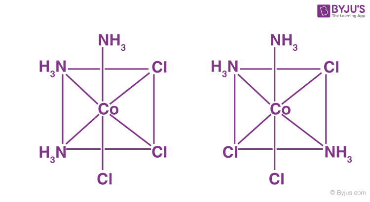
Case 2: If two waves are out of phase, they are subtracted from each other, resulting in the new wave's amplitude being equal to A – B.

Characteristics of Bonding Molecular Orbitals
Characteristics of Anti-bonding Molecular Orbitals
They are represented by
Why are Antibonding Orbitals Higher in Energy?
Bonding molecular orbitals often have lower energy levels than anti-bonding molecular orbitals. This is because in bonding Molecular Orbitals, the nuclei attract the electrons in the orbital, while in anti-bonding Molecular Orbitals, the nuclei repel each other.
Difference between Bonding and Antibonding Molecular Orbitals
Molecular Orbital Theory | |
Bonding Molecular Orbitals | Anti-Bonding Molecular Orbitals |
Bonding molecular orbitals are molecular orbitals created by the additive effect of atomic orbitals. | Anti-bonding molecular orbitals are created by the subtractive effect of atomic orbitals. |
In the case of bonding molecular orbitals, the probability of finding electrons is higher. | Antibonding molecular orbitals have a lower probability of finding electrons. There is also a node where the electron density is zero between the anti-bonding molecular orbitals of two nuclei. |
These are made up of a mixture of + and + as well as – of – electron waves. | The intersection of the + and – parts creates these. |
In the internuclear field, the electron density in the bonding molecular orbital is strong. As a result, the nuclei are protected from each other, and repulsion is reduced significantly. | In the internuclear field, the electron density in the antibonding molecular orbital is very low, so the nuclei are directly exposed to each other. As a result, the nuclei are less protected from one another. |
The bonding molecular orbitals are denoted by | The anti-bonding molecular orbitals corresponding to the corresponding anti-bonding molecular orbitals are described by σ∗ , π∗, δ∗. |
Stabilization energy is defined as a decrease in the energy of bonding molecular orbitals compared to the energy of combining atomic orbitals, and destabilisation energy is defined as an increase in the energy of anti-bonding molecular orbitals.
Consider the following: Magnetic fields attract paramagnetic materials, which have unpaired electrons, while diamagnetic materials, which do not have unpaired electrons, are weakly repelled by such fields. Determine whether each of the following molecules is paramagnetic or diamagnetic by constructing a molecular orbital image.
B2
C2
O2
NO
CO
Features of Molecular Orbital Theory
Key Takeaway:
The Aufbau principle states that the lowest-energy orbitals are filled first, and the Pauli exclusion principle states that an orbital can only have two electrons with opposite spins.
When there are many MOs with equal energy, Hund's rule states that the electrons occupy the MOs one at a time until two occupy the same MO.
References:
1. J. M. Chilton and J. J. Fardy, J. Inorg. Nucl. Chem., Vol. 31, 1171-1177, (1969).
2. N. A. Talvitie, Anal. Chem., Vol. 43, p 1827, (1971).
3. N. Shinohara and N. Kohno, J. Nucl. Sci. & Techol., Vol. 34(4), 398-401, (1997).
5. M. Y. Suh, et al. KAERI/TR-2354/2003, (2003).
5. M. V. Ramaniah, et al., BARC-736, (1974).
6. F. Nelson et al., J. Chromatog. 14, 258-260 (1964).
