Unit - 4
Electrochemistry-II
4.1.1 Concentration cell:
Concentration cells are electrochemical cells that are made up of two half-cells with identical electrodes but different concentrations. The more concentrated half-cell is diluted as the cell as a whole seeks to achieve equilibrium, and the lower concentration half-cell has its concentration boosted via electron transfer between these two half cells. As a result, a potential difference is formed as the cell approaches chemical equilibrium. Below is a comprehensive diagram of a concentration cell and the discharge process.
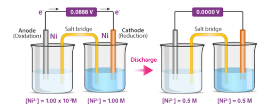
Types of Concentration Cells
Concentration cells can be classified into two types, namely:
- Electrode Concentration Cells
- Electrolyte Concentration Cells
Electrode Concentration Cells
Each half-cell is made up of identical solutions that serve as electrolytes. The concentration of the electrode in the half-cells, however, differs (the electrodes are made up of the same material).
A cell consisting of two hydrogen electrodes that are subjected to varied pressures but are submerged in the same solutions is an example of this sort of cell (containing hydrogen ions).
Electrolyte Concentration Cells
These cells are made up of identical electrodes immersed in electrolyte solutions of variable concentrations. The electrolyte in these cells tends to diffuse from higher concentration solutions to lower concentration solutions.
A cell with a Zn/Zn2+(0.1M) anode and a Zn2+(0.01M)/Zn cathode is an example of this type of cell. The reduction of Zn2+ ions into metallic zinc at the cathode causes electron transport from the anode to the cathode in this cell.
4.1.2 Components of the Concentration Cell
Salt Bridge
The salt bridge is the ideal method for separating the two half-cells while also providing an ion transfer pathway. Ions passing via electric lines would react with them. In the absence of a salt bridge, electrons from the incoming flow of electrons from the other half cell would pile up in one half cell.
A cell's two compartments must be divided so that they do not combine, yet they cannot be entirely separated without allowing ions to pass through. A wire could not be used to connect the two compartments because it would react with the ions flowing from one to the other. As a result, a salt bridge is an essential component of a concentration cell. It solves the major issue of electrons accumulating excessively in the right beaker. Electrons are migrating from the left side, or left beaker, to the right side, or right beaker, causing this accumulation. A salt bridge can take several forms, including a salt solution in a U-tube or a porous barrier (direct contact). By pushing ions to the left side, or left beaker, it balances the charge. The salt bridge is indicated by the double lines in the textual expression that shows what happens in specific reactions. As an example, consider the following:
Cu2+(1 M) |Cu2+(1 M) |Cu2+(1 M) |Cu2+(1 M) |Cu2+(1 M) |Cu2+(1 M) |Cu2+(1 M) |Cu
The salt bridge is represented by the double lines between the Zn2+(1 M) and the Cu2+(1 M). The single lines, on the other hand, do not depict bridges; they depict phase transitions, such as from solid zinc to liquid zinc solution. This is not improper if there is a comma where you would expect to see a single line. It simply means that no phase transitions took place.
Electrode
The cathode (right side) and anode (left side) are the two electrodes (left side). The anode loses electrons and is where oxidation takes place, whereas the cathode is where electrons collect and reduction takes place.
Voltmeter
The voltmeter is used to determine the cell's potential. Electromotive force is another term for cell potential (or EMF). In most cases, the voltmeter is situated halfway between the two half-cells.
To summarise, a concentration cell is a galvanic cell in which the half-cells contain the same chemical but at varying concentrations. While advancing towards chemical equilibrium, these cells produce a minor potential difference that can be monitored with a voltmeter.
4.1.3 Use of concentration cell:
A pH metre is a sort of concentration cell that employs a concentration cell's basic setup to determine the pH, or acidity/basicity, of a specific solution. It consists of two electrodes as well as a voltmeter. One of the electrodes, the glass electrode, is made up of two parts: a metal wire (usually silver chloride) and a semi-porous glass section filled with a potassium chloride solution with a pH of 7 that surrounds the AgCl. The reference electrode, which has a potassium chloride solution encircling a potassium chloride wire, is the other electrode. The second electrode's aim is to provide as a comparator for the solution being evaluated. When the glass electrode comes into touch with a solution with a variable pH, the hydrogen ions react with the metal ions, creating an electric potential. The voltmeter, which is attached to the electrode, then measures this potential. The higher the voltage, the more hydrogen ions are present in the solution, indicating that it is more acidic.
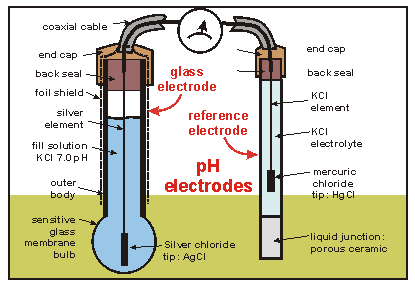
An example of a pH meter
4.1.4 Junction potential:
Any interface, or junction, where there is a charge separation creates a potential. When a metal electrode comes into touch with a solution containing its cation, for example, a potential can arise. The Nernst Equation can be used to describe this type of potential.
When electrolyte solutions of different composition are separated by a boundary, such as a membrane or a salt bridge, a potential can form (a gel-filled tube containing an inert electrolyte that connects half-cells to allow charge neutrality to be maintained).
The two solutions could have the same ions but at different concentrations, or they could have completely different ions. The mobilities of these ions vary, which implies they travel at various speeds.
A porous glass frit, for example, could divide two NaOH solutions:
0.01 M NaOH / NaOH (0.001 M)
OH- travels at a rate of about 5 times that of Na+...

Developing of a potential at the interface, or boundary, between the two solutions.

So now for an electrochemical cell containing a salt bridge, the cell potential is actually:
Ecell=Ecathode−Eanode+Ejunction
Typical liquid junction potentials range from a few mV to 40 mV, depending on the electrolyte solutions' identities and concentrations.
The junction potential of a simple cell, such as the one described on the preceding page, may be determined using the ion mobilities. Most practical electrochemical cells, on the other hand, are more sophisticated. The standard addition quantitation method can be used to adjust for or eliminate mistakes caused by a junction potential. A potential measurement is performed on a solution containing only the analyte ion in this case. After that, a known volume of standard ion solution is “spiked” into the solution, and a second potential measurement is taken. This approach can be repeated for a number of spikes (multiple standard addition method). It's safe to presume that adding the standard has no effect on the junction potential. In the Experimental section of this topic, you can read more about this quantification method in the Chloride Experiment.
4.1.5 Potentiometric titration:
What is Potentiometric Titration?
It is the technique for determining the quantity of a specific test substance by adding titrant in small increments until the entire test substance reacts. The potential difference between the two electrodes (the reference and indicator electrodes) is measured after the titration process in conditions when the thermodynamic equilibrium is maintained and the current running through the electrodes does not affect it.
Potentiometric Titration Principle
A laboratory method for determining the concentration of a particular analyte is potentiometric titration. It's utilised to figure out what acids are. A chemical indicator is not used in this procedure. Instead, the electric potential is measured across the substance.
Potentiometric Titration Method
Two electrodes are used in potentiometric titration: an indication electrode and a reference electrode (generally a hydrogen electrode or a silver chloride electrode). The indicator electrode and the ions of the analyte, which is usually an electrolyte solution, form a half-cell. The reference electrode forms the other half-cell.
The formula below can be used to compute the overall cell potential.
Ecell = Eind – Eref + Esol
Esol is the potential difference between the indication and reference electrodes in the electrolyte solution.
Every interval where the titrant is measured and applied, the entire cell potential, Ecell, is determined. Now, as shown below, a graph is drawn with the Potential difference on the Y-axis and the volume on the X-axis.
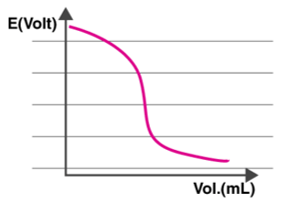
The electric potential of the cell is proportional to the concentration of ions in contact with the indicator electrode, as shown in the graph. As a result, the Ecell is measured after each titrant addition.
Types of Potentiometric Titration
Acid-base titration, redox titration, complexometric titration, and precipitation titration are the four types of titrations that fall under the category of potentiometric titration. Below is a quick summary of each of these forms of titration.
Acid-Base Titration: This sort of potentiometric titration is used to estimate the concentration of a given acid/base by neutralising it precisely with a known-concentration standard solution of base/acid.
Redox Titration: A redox reaction occurs between the analyte and the titrant in this sort of potentiometric titration. The treatment of an iodine solution with a reducing agent to form the iodide ion is an example of this type of titration (a starch indicator is used to get the endpoint).
Complexometric Titration: Chelatometry is another name for this sort of titration. A coloured complex is created in this procedure, signifying the titration's end point. This approach is used to identify a metal ion combination in a solution.
Precipitation Titration: An insoluble precipitate is created as a result of an interaction between the analyte and the titrant in this type of titration. When the addition of the titrant no longer generates a precipitate, the titration is complete.
4.1.6 Electrodes used in potentiometric titrations
The potentiometric measuring experimental setup consists of a set of indicating and reference electrodes, or two identical indicating electrodes, which should be handled with care. The electrodes must be attached to the electrode holder at all times. After the experiment, clean the electrodes and reassemble them in their respective housings.
Electrode made of glass. The indicator and reference electrodes are housed in the same body in a combined glass reference electrode. It should be handled with extreme caution: never contact the glass portion of the electrode with anything other than delicate tissue paper. The glass electrode's bulb and the reference electrode's diaphragm should be immersed in solution while in use. The combined glass electrode should be immersed in a 2 M KCl solution for short-term storage. The pH calibration is done with buffer solutions that have a known pH. Some buffers' pH levels are temperature-dependent. Calibration and measurements must be done at the same temperature for optimal accuracy.
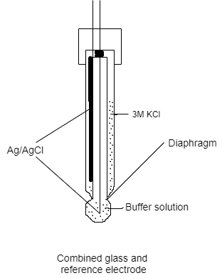
Specific ions in a mixture of ions are detected using ion-selective electrodes. Ion-selective membrane, the sensor element, is built similarly to a glass electrode. A standard addition method is frequently used to calibrate ion-selective electrodes.
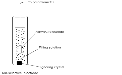
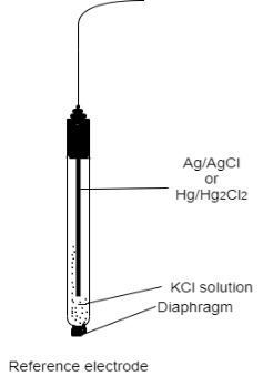
Silver wires with a diameter of 1-2 mm are used as silver indicating electrodes. The silver-salt precipitate should be periodically scraped from the electrode surface when employed in precipitation titration (mechanically with fine grade emery paper, or chemically immersing the electrode in NH3 solution). It is, however, easier to prevent electrode coating by adding a surfactant such as polyvinyl alcohol (1 drop 0.3 percent PVA to every 5 ml of solution).
A gold wire is said to be lightly amalgamated to make mercury-coated indicating electrodes. The disadvantage of using gold is that the amalgam formation consumes it over time. Silver wire, on the other hand, can last a long time if utilised instead of gold. The instructor prepares the mercury-coated silver electrode in a hood (mercury vapours are deadly!). The silver wire is (a) rubbed with emery paper, rinsed with distilled water, and dried with tissue; (b) dipped in mercury to make an amalgam; and (c) the mercury is softly spread on the wire with soft tissue. This electrode does not need to be replaced after numerous titration cycles. Step (a) can be skipped in the case of renewal.
In redox potentiometric titrations, platinum redox electrodes are utilised. On the platinum electrodes, an excessive amount of oxidant oxide coatings form. The electrode's potential response is altered, and the coating must be removed. Pre-treatment efficiency is accomplished by cathodically polarising the platinum electrode in 0.5 M H2SO4 for 5 - 15 minutes at a current density of 0.5 mA/cm2. As an auxiliary electrode, platinum wire is preferred.
Potentiometric titrations rarely employ gold redox electrodes. In terms of rate of response and stability toward oxide development, gold electrodes are better behaved than platinum electrodes, according to our recent experience. In the continuous method of titration, these characteristics are critical. The employment of gold electrodes in the continuous titration of ascorbic acid with bromine, where the response of the platinum electrode is inadequate, is a good example.
Electrodes of reference in potentiometric titration, calomel and silver/silver-chloride electrodes are often employed. A mercurous sulphate electrode can be employed in the case of suspected chloride interferences (as in halide determination). A home-made Ag/AgCl/1 M KCl reference electrode is utilised in the following series of tests. At 250C, it has a potential of -19 mV vs SCE.
Exp. 1. Complexometric titration of Ca2+ and Mg2+ in drinking water
Chelating agents
A chelating agent (ligand) is a multidendate condensing molecule that forms a 1:1 complex (chelate) with a metal ion Mz+, regardless of the metal ion's charge z.
For two reasons, complexometric titration with chelating agent Y (comprising n complexing groups) is considerably superior to titration with monodendate ligand L (of the same kind).
(1) Due to thermodynamic considerations, the chelate MY complex is more stable than the MLn complex. The shift in free energy,
Where is the enthalpy and is the entropy, is characterised by comparable but extremely distinct values. The dissociation of MLn produces more disorder with the production of n+1 species, compared to two species for the chelate.
(2) With monodendate ligands, stepwise complexation is frequently characterised by formation constants that are quite near to each other. In contrast to a chelate, where a single 1:1 complex is normally created, there are various types of complexes in the area of the end point.
With six complexing groups, EDTA (ethylenediaminetetraacetic acid) is one of the most extensively used chelating agents (two nitrogen and four carboxylic groups). With the exception of alkali metal ions, EDTA titrations have been used to determine the majority of metal cations. Controlling the pH allows for selectivity. Ca2+ and Mg2+, on the other hand, have similar formation constants (Kf = 5.0•1010 and 4.9•108, respectively), making distinct detection impossible. The total concentration of Ca2+ and Mg2+ is determined by titrating with EDTA.
Because of the substantial difference in Kf (1.0•1011 and 1.6•105 for Ca2+ and Mg2+, respectively), EGTA is a good chelating agent for determining [Ca2+] alone.
The mercury electrode, Hg/HgY, MY, Mn+
The mercury electrode can serve as an indicating electrode for complexometric titrations when it is used as an electrode of the third kind.
Let us consider a mercury electrode dipped in a solution containing the following relevant species: Hg2+, M2+ (metal ions), Y4-, HgY2-, MY2-.
The following processes are to be considered:


Where K´f is the conditional formation constant (cf., ref. 4 in Recommended Literature).
Combining the previous equations yields the expression for the equilibrium potential.

The potential of the mercury electrode varies with the variation of the concentrations of HgY2-, MY2- and M2+. Around the equivalence point, however, [MY2-] is almost constant (why?); [HgY2-] is virtually constant when the condition K’f, HgY2- >> K’f, MY2- is fulfilled (why?). Since HgY2- forms a very stable complex, the inequality is fulfilled for most metal ions. The concentration of M2+ varies by several orders of magnitude around the equivalence point.
The electrode potential acts as a trustworthy signal for the variation of the concentration of the uncomplexed metal ion since the first three terms on the right-hand side of the final equation are practically constant around the equivalence point. As a result, the electrode is an effective tool for detecting the end-point of complexometric titrations.
The presence of Hg (II) species is required for the electrode to work properly, according to the aforementioned thermodynamic treatment. This is why, in complexometric titrations, a small quantity of the EDTA complex of Hg (II) is injected into the solution (why Hg (II) in the complex form rather than Hg2+?).
4.2.1 Atoms
The majority of the Universe is made up of matter and energy. The capacity to work is defined as energy. Matter has mass and takes up room. Basic elements make up all matter, and they can't be split down into compounds with distinct chemical or physical properties. Elements, for example, are compounds made up of only one type of atom. Diamond and graphite are both made up of carbon atoms. Gold atoms are the only type of atom in pure (24K) gold. Atoms are the smallest particles that can be separated into an element. The notion of the atom was conceived by ancient Greek philosophers, who saw it as the primordial particle that could not be broken down. We now know that the atom is divisible, often releasing enormous energies as in nuclear explosions or (in a controlled manner in) thermonuclear power plants, thanks to the work of Enrico Fermi and his colleagues.
During the 1800s, subatomic particles were discovered. For our purposes, we'll focus on only three of them, which are included in Table 1. Each atom has at least one proton, which is located in the centre (or nucleus) of the atom. Protons have a positive charge and a mass of about 1 atomic mass unit (amu). The amount of protons in each element varies, for example, Hydrogen has one proton whereas Helium has two.
The neutron is found in the atomic nucleus as well (except in Hydrogen). The neutron is a neutral particle with a mass of little more than 1 amu and no charge. According to some scientists, the neutron is composed of a proton and an electron-like particle.
The electron is a tiny particle that exists outside of the nucleus. The specific position of electrons is difficult to nail down since they move at speeds close to the speed of light. Orbitals, or places where electrons have a high statistical likelihood of appearing, are occupied by electrons. An electron has a charge of -1. It has a very small mass (approximately 1800 electrons are needed to equal the mass of one proton).
Table shows the subatomic particles that are used in biology.
Name | Charge | Location | Mass |
Proton | +1 | Atomic nucleus | 1.6726 X 10⁻²⁷ kg |
Neutron | 0 | Atomic nucleus | 1.6750 X 10⁻²⁷ kg |
Electron | -1 | Electron orbital | 9.1095 X 10⁻³¹ kg |
The number of protons in an atom is known as its atomic number. Each element has its own distinct personality. The number of protons and neutrons in an atom is measured by its atomic mass (also known as its atomic weight). Isotopes are atoms of the same element with different quantities of neutrons (but the same atomic number). Figures 1 and 2 show how isotopes can be used to establish ancient peoples' diets by calculating the amounts of isotopes in mummified or fossilised human tissues. Isotopic tracers can be used to interpret biochemical processes. Radioactive isotopes can be used to determine the age of fossils and artefacts, either directly on the fossil (if it is young enough) or on the rocks that surround the fossil (for older fossils like dinosaurs). Isotopes are also employed in medical diagnostic and therapeutic processes as a source of radiation.
1st Figure It's worth noting that each of these hydrogen isotopes only has one proton. Isotopes differ in the number of neutrons they have rather than the number of protons they have.
Some isotopes are radioisotopes, meaning they decay spontaneously and emit radiation. Other isotopes have a long half-life. Carbon-14 (symbol 14C) and deuterium are two radioisotopes (also known as Hydrogen-2; 2H). 12C and 1H are stable isotopes.
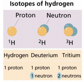
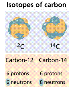
Figure. Carbon has three isotopes, of which carbon-12 and carbon-14 are the most well-known.
Below figure shows a variation of the Periodic Table of the Elements, which contains a wealth of information about various elements. Each Roman numerated column on the label (at least those ending in A) indicates the number of electrons in the atom's outer shell. The table's numbered rows indicate how many electrons shells an atom possesses. Thus, in column IA, row 1, Hydrogen has one electron in one shell. In column VA, row 3, phosphorus has five electrons in its outer shell, for a total of three shells. Image courtesy of the University of Akron's James K. Hardy's chemistry website.
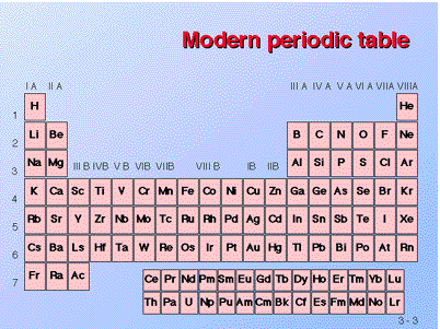
Figure: The Elements' Periodic Table
4.2.2 Electrons and energy
Electrons appear to cross the energy-matter divide because they move so quickly (roughly at the speed of light). Over a century ago, Albert Einstein devised the famous E=mc2 equation, which relates matter and energy. We think of electrons as both particles of matter (mass being a feature of matter) and units (or quanta) of energy as a result of his (and others') work. When electrons are exposed to energy, they will absorb some of it, as seen in Figure.
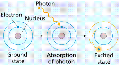
Figure: Energy excites an electron, causing it to "jump" to a different electron (energy) level known as the excited state.
An orbital is also a region of space where an electron can be detected 90% of the time. Orbitals come in a wide range of forms. Each orbital has a distinct energy state as well as a distinct form. The spherical orbital is a spherical orbital. Because each orbital can only store two electrons, atomic numbers greater than two must fill the remaining orbitals. Along the x, y, and z axes, the px, py, and pz orbitals are dumbbell shaped. Figure 5 depicts these orbital shapes.
Energy levels (also known as electron shells) are separated from the nucleus by a particular "distance." The major energy levels into which electrons fit are K, L, M, and N (from the nucleus outward). The electron configurations are sometimes numbered, such as 1s22s22p1 (where the first shell K is indicated with the number 1, the second shell L with the number 2, etc.). This nomenclature tells us that the first energy level (shell) has two electrons in its s orbital (the only orbital it can have), and the second energy level has a maximum of two electrons in its s orbital, plus one electron in its p orbital for the atom indicated in this paragraph.
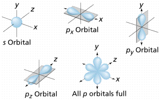
Figure: Orbital geometry. S-orbitals are spherical, while p-orbitals have a dumbbell or figure 8 shape.
4.2.3 Chemical Bonding
Chemists grouped the then-known elements according to chemical bonding during the nineteenth century, observing that one group (the far-right column on the Periodic Table, known as the Inert Gases or Noble Gases) tended to occur in elemental form (in other words, not in a molecule with other elements). It was eventually discovered that this group of elements has outer electron shells with two (as in Helium) or eight (Neon, Xenon, Radon, Krypton, and so on) electrons.
In general, atoms gain or lose outer electrons to reach a Noble Gas outer electron shell configuration of two or eight electrons for the atoms we are likely to encounter in biological systems. The amount of electrons acquired or lost is unique to each element, and it ultimately affects the number and types of chemical bonds that can be formed by its atoms. Figure 6 depicts atomic diagrams for numerous atoms.
Figure: Atomic diagrams showing how the outer electron shells are filled.
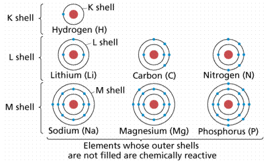
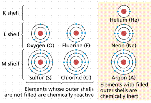
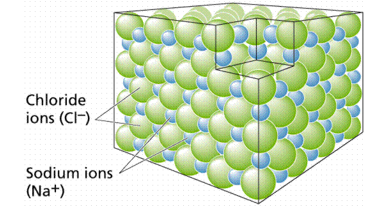
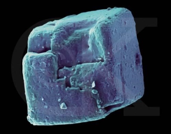
When atoms gain or lose electrons, they create ions and establish ionic connections. The element chlorine belongs to a group of elements with seven electrons in their outer shells (see Figure 6). Members of this group usually gain one electron, giving them a -1 charge. Sodium belongs to a different group of elements that have only one electron in their outer shells. Members of this group are more likely to lose that outer electron, resulting in a +1 charge. Cl- (the symbol for the chloride ion, using the Greek word natrium) and Na+ (the symbol for the sodium ion, using the Greek word natrium) form an ionic connection, resulting in the molecule sodium chloride, as illustrated in Figure 7. Ionic bonds are most commonly formed between Group I (elements with one electron in their outer shell) and Group VIIa (elements with two electrons in their outer shell) (having seven electrons in their outer shell). Because such interactions are weak, they tend to dissociate in water, resulting in solutions that contain both Na and Cl ions.
TOP: The formation of a sodium chloride crystal. Six negatively charged chloride ions surround each positively charged sodium ion, and six negatively charged sodium ions surround each negatively charged chloride ion. Electrical neutrality is the overall impact.
When atoms share electrons, they form covalent bonds. Electrons can be shared because they move so quickly, essentially filling or emptying the outer shells of the atoms engaged in the interaction. Electron-sharing bonds are the name for these types of bonds. Child custody can be compared to electrons, in that children tend to spend some time with one parent and the balance of their time with the other. The electron clouds around the atomic nuclei overlap in a covalent link, as shown in Figure 8.
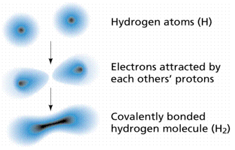
Figure: A covalent link is formed between two hydrogen atoms.
Carbon (C) belongs to Group IVa, which means its outer shell has four electrons. Carbon may either gain or lose four electrons to become a "happy atom." Carbon can become a happy atom by sharing electrons with other atoms, filling and emptying its outer shell in a cycle similar to the four hydrogens depicted in Figure.
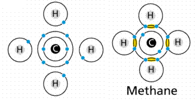
Figure: Covalent bond formation in methane.
Carbon requires four electrons to share, hence it has four slots. Every hydrogen contributes an electron to one of these slots. Each hydrogen must fill one slot at the same time, which is accomplished by sharing an electron with the carbon.
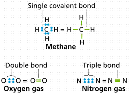
There are four covalent bonds in the molecule methane (chemical formula CH4), one between Carbon and each of the four Hydrogens. An electron is contributed by carbon, while an electron is contributed by hydrogen. A single bond is defined as the sharing of a single electron pair. A double bond is formed when two pairs of electrons are shared, as in carbon dioxide. As in acetylene or nitrogen gas, triple bonds are known, in which three pairs (six electrons total) are shared. Figure 10 depicts the various forms of covalent bonding.
When electrons spend more time with one atom in a bond than the other, this can be problematic. In these situations, a polar covalent bond form. A good example is water (H2O). Because the electrons spend so much time with the oxygen (oxygen has a higher electronegativity, or electron affinity), the molecule's end gets a little negative charge. The loss of electrons from the hydrogen end, on the other hand, leaves a somewhat positive charge. As a result, the water molecule is polar, with both positive and negative sides.
The weak electrical pull between the positive end of one molecule and the negative end of another form’s hydrogen bonds, as seen in Figure 11. Individually, these bonds are quite weak, but when combined in large enough quantities, they can keep molecules together or form three-dimensional shapes.
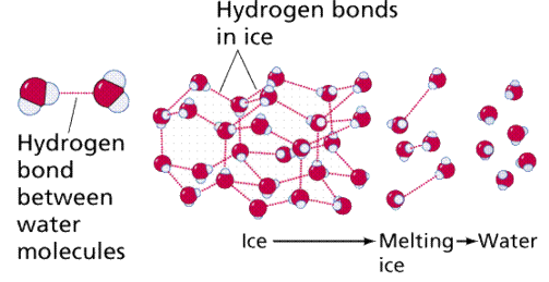
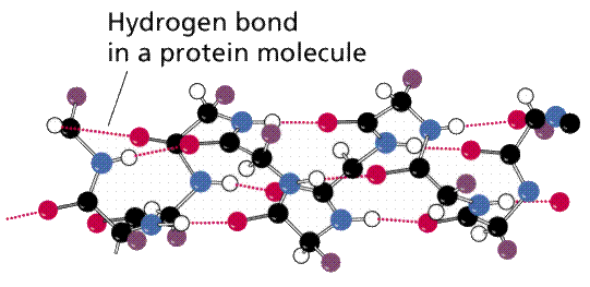
Figure shows the formation of a hydrogen bond between one water molecule's hydrogen and another water molecule's oxygen. BOTTOM LINE: The existence of polar regions in the amino acids that make up a protein allows hydrogen bonds to form, giving the molecule a three-dimensional shape that is often critical to its appropriate function.
4.2.4 Chemical reactions and molecules
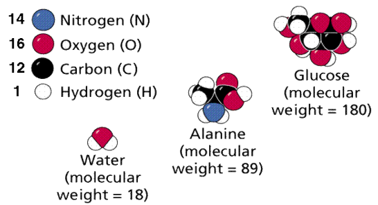
Molecules, as shown in Figure, are compounds in which the constituents are in defined, fixed ratios. One of the three types of chemical bonds outlined above usually holds those atoms together. Water, glucose, and ATP are just a few examples. Compounds with changeable formulas/ratios of their constituents are known as mixtures. Take, for instance, soil. Molecular formulae are expressions of a substance's composition in the simplest whole-number terms. The sugar glucose, for example, has 6 carbon atoms, 12 hydrogen atoms, and 6 oxygen atoms per repeating structural unit. C6H12O6 is the chemical formula.
Molecular weights are calculated by adding the weights of the atoms that make up the molecule.
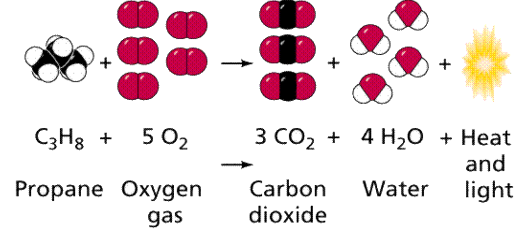
Chemical reactions can be found in nature, and some may also be done in a lab. Figure 13 depicts one of these reactions. Chemical equations are representations of how various processes take place in a linear format. When two independent reactants are joined together, for example, A + B ----> AB, a combination reaction occurs. When a compound is broken down into two products, such as AB -----> A + B, disassociation reactions occur.
Graph 13. A chemical reaction diagram depicting the burning of propane with oxygen, which produces carbon dioxide, water, and energy (as heat and light). A camping stove, as well as certain welding torches, undergo this chemical reaction.
Biological systems are founded on the chemical bonding properties of carbon, which are unique to each species. Major organic chemicals (those associated with or formed by the actions of living things) usually include some ratios of the following elements: C, H, N, O, P, S.
Key takeaway:
- The electric force of electrons attracts them to any positive charge; in an atom, electric forces bond the electrons to the nucleus. The electrons of an atom behave like particles orbiting the nucleus in various ways. In others, the electrons act like waves around the nucleus that are frozen in place.
- Two Up quarks and a Down quark make up a proton, while two Down quarks and an Up quark make up a neutron. Because their masses are far lower than two-thirds of the mass of a proton or neutron, determining their masses is difficult.
- Many atoms have a positively charged nucleus made up of protons and neutrons that is surrounded by a cloud of negatively charged electrons. At its most fundamental level, an atom is any particle of matter that contains at least one proton. The following are some examples of atoms: neon (H) hydrogen (Ne).
4.3.1 Electrostatics in chemistry:
In weak intermolecular interactions, electrostatics plays a crucial role. The goal of this series is to comprehend these electrostatic properties. The fundamental concepts of electrostatics as applied to atoms and molecules are presented in this article. The electric field and potential generated by a set of discrete and continuous charge distributions, as well as their graphic depiction, are explored. Electrostatic fundamental theorems are also summarised.
Introduction
Atoms and molecules are the operational building units of matter, according to chemists. The total energy of an atom is dominated by the electrostatic interaction energy between the positively charged nucleus and negatively charged electrons. Molecules are formed when atoms come together. The chemistry of the covalent bond, or molecular chemistry, is concerned with the structures, characteristics, and reactions of these molecules. Supra11UJlecular chemistry, which is defined as chemistry beyond the molecule, is a novel discipline of chemistry that deals with complexes of two or more molecular subunits that has emerged in recent years. The fundamental issue of molecular recognition has various applications in the chemical sciences, including analytical chemistry, bioinorganic and bioorganic chemistry, catalysis, and enzyme chemistry, among others. Electrostatics is well acknowledged to play a key role in these recognition processes. As a result, an understanding of electrostatics is required for a proper background in supramolecular science. Basic molecular electrostatics and its applications to weak intermolecular interactions will be explored in this series of papers.
Electrical Charges and Coulomb's law
The concept of an electric charge underpins the development of electrostatics. The following are some experimental facts about electric charges: I There are two types of electric charges in nature. Positive and negative charges are the terms for these two types of charges (the present labels of positive and negative to charges of proton and electron, respectively, are indeed a historical accident).
Ii) The force between two-point charges is proportional to their product and inversely proportional to the square of their distance, and it acts along the line that connects them.
The above experimental results are combined together in Coulomb's law

Here F2, l is the force acting upon q1, r1 and r2 are the position vectors of ql and q2 respectively, with respect to an arbitrary origin 0 as shown in Figure 1.
The presence of other point charges has no effect on the electrostatic forces between two-point charges. When extra point charges are introduced, the force F2, l (Equation 1) remains unchanged. These forces are pair-wise additive, and the total force Fl owing to point charges q' q3.... Qn on the point charge q1 is given by


Figure shows the force F2, 1 exerted by q2 on q1' in a schematic diagram. The charges q1 and q2 are respectively situated at r 1 and r 2.
The superposition principle refers to the additive behaviour of electrostatic forces.
4.3.2 Coulomb's law
Coulomb's law gives the magnitude of the electrostatic force (F) between two charges:

The charges are q 1 and q 2, the distance between them is r, and the proportionality constant is k. The coulomb is the SI unit for charge. The following estimated value for k will yield the force in newtons if the charge is in coulombs and the spacing is in metres: • m 2/C 2 • k = 9.0 10 9 N The direction of the electrostatic force is determined by the charge signatures. Charges that are similar repel each other, while charges that are dissimilar attract each other.
Coulomb's law can also be written in terms of the permittivity of free space, which is a constant (0):

When the permittivity constant is used, Coulomb's law is

The charge of one proton or electron is the most fundamental electric charge. e = 1.602 10 19 coulombs is the value (e). To match the charge of one coulomb, it takes around 6.24 10 18 additional electrons; consequently, it is an extremely enormous static charge.
The forces between each pair of charges must be determined for a system of charges, and the net force on a specific charge is the vector sum of these forces. This approach is demonstrated in the following problem.
Example 1: Consider two equal charges of Q, the value of which is unknown in coulombs. At a distance of X, the force between two of these charges equals F. Three charges (3 Q) are put at point A, which is a distance X from point B, as shown in Figure. At point B, which is X/2 distance from point C, which has one charge, one charge (Q) is placed. What is the charge's net force at point B?
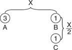
Figure: Arrangement of point charges for the example.
Solution: Proportional reasoning can be used to address this dilemma. On the one charge at B, the force of 3 Q will be 3 F. The force will be four times stronger than at a distance of X, or 4 F, because the single charge is half X from B. Because the forces of 3 F and 4 F are perpendicular, the resultant force is 5 F, or

The direction is found from the tangent: θ −1 = tan 4/3 = 53°
4.3.3 Electric fields and lines of force
When a little positive test charge is brought close to a large positive charge, it is pushed away from the bigger charge by a force. The electrostatic force calculated by Coulomb's law is smaller when the test charge is far from the large charge than when it is close. An electrostatic field is made up of information on the direction and amplitude of an electrostatic force caused by a fixed charge or collection of fixed charges. The electric field is defined as the force per unit charge exerted at a given position on a modest positive test charge (q 0). In terms of mathematics,

It's worth noting that the force and the electric field are both vector quantities. The test charge must be small enough that its field does not interfere with the field of the set charges being studied. Newtons per coulomb (N/C) is the SI unit for electric field.
The electric fields surrounding a positive charge and a negative charge are seen in Figure. Field lines or force lines are the names given to these lines.
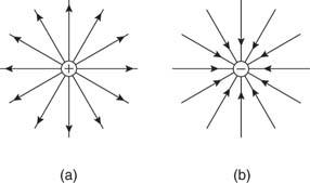
Figure: (a) Positive and (b) Negative point charge electric field lines
Figure depicts the electric fields for plates with opposite charges, plates with similar charges, and plates with opposing charges.
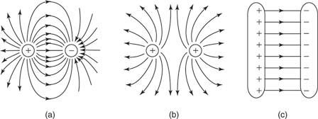
Figure: Electric field lines of (a) two opposite charges, (b) two like charges, and (c) two oppositely charged plates.
The lines originate on positive charges and end on negative charges, and the number of lines drawn emerging from or terminating on a charge is proportionate to the magnitude of the charge, according to the principles for drawing electric field lines for any static arrangement of charges.
In a charge-free region, no two field lines ever intersect. (Only one line can be at each place since the tangent to the field line represents the direction of the resultant force.)
The line is perpendicular to the conducting surface.
Electric flux
The number of field lines that flow across a given surface is known as electric flux. Electric flux lines emerge from a point charge in Figure and pass through an imaginary spherical surface with the charge at its centre.
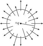
Figure: Electric flux due to a point charge + q
The following is an example of a definition: = E • A, where E is the electric field, A is the area perpendicular to the field lines, and (the Greek symbol phi) is the electric flux. Electric flux is a scalar quantity measured in N • m 2 / C 2. The formula is = EA cos if the surface under consideration is not perpendicular to the field lines.
Flux is the closed integral of the dot product of the electric field vector and the vector A in general terms. The outward drawn normal to the imaginary surface is the direction of A. = E • dA is a mathematical formula. When flux lines leave a surface, they are positive, and when they enter a surface, they are negative.
4.3.4 Gauss's law
Gauss's law gives a mechanism for calculating any electric field; however, it is only useful for fields with highly symmetric constant charge distributions. The net electric flux through any closed surface, real or imaginary, is equal to the net electric charge enclosed within that surface divided by. As a result, if a closed surface has no charge, there are as many flux lines entering the surface as there are exiting it. The gaussian surface is the imaginary surface required to implement Gauss's law. In terms of algebra,

Or in integral form,

Where is the permittivity constant and is the angle between the direction of E and the outward direction of normal to the surface.
Consider the computation of a point charge's electric field. Figure depicts a point charge, its field direction, and a gaussian surface. Because the electric field is directed outward and perpendicular to the gaussian surface, is 90 degrees, and cos = 1. The law of Gauss is

Substitute in the area of a sphere, and the left side reduces to

Or

It is the same formulation as Coulomb's law and the force-based description of an electric field.
The expression for the field due to a thin conducting shell of charge is deduced as follows. The electric fields for (a) a radius (R) shell, (b) the gaussian surface for outside the shell, and (c) the gaussian surface for within the shell (c) of radius are shown in Figure(r).
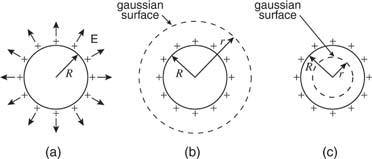
Figure: A charged R-radius spherical shell. (b) A gaussian sphere having a radius greater than R. (c) A sphere with radius r R with a gaussian surface.
When outside the shell of charge, as in Figure (a), the left side of Gauss's equation reduces to the following expression for the same reasons given for a point charge:

Therefore,

As a result, the electric field outside a sphere of charge is the same as if the same amount of charge were concentrated in the sphere's centre.
There is no electric field inside the uniformly charged spherical shell because the gaussian surface inside the sphere encloses no charge. Because all of the charge in a solid conductor is concentrated on the surface, the same proof applies. The charge will not be evenly spread over an uneven form since the electric field within even an irregularly shaped conductor is zero. The charge will tend to collect on projecting areas on the conductor's exterior.
4.3.5 Potential difference and equipotential surfaces
The charge distributions in the earlier cases were spherical, hence the gaussian surface was a sphere. A cylinder is the correct gaussian surface to employ when determining the electric field of a sheet of charge or a line of charge.
Example 2: Calculate the electric field of a nonconducting infinite charge sheet. On both sides of the sheet, the electric field is directed outward. The charge per square metre is (the Greek letter sigma). The electric field and gaussian surface are depicted in Figure.
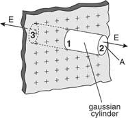
An endless sheet of charge must be extended above and below a gaussian cylinder.
Because the area of the closed cylindrical gaussian surface is the sum of the areas of the left end, right end, and wall, EA cos = (EA cos) left end + (EA cos) right end + (EA cos) wall. The electric field is perpendicular to the wall, which is perpendicular to the outward normal of the wall area; hence, the final term on the right is zero. E is parallel to the outward normal at both ends, hence (EA cos) left end + (EA cos) right end = 2 EA, where A is the area of the gaussian cylinder's end. The product of the charge per unit area and the area equals the total charge inside the gaussian surface; so

And

The magnitude of the electric field is independent of the distance between the plate and the observer. The electric field is very consistent. In the case of finite charge plates, the electric field is reasonably uniform close to the charged plate.
The electric field produced by two parallel plates is double that of a single sheet of the same charge:

Or

The charge on each plate is q, and the area of each plate is A. The electric field will exist between the plates and be zero outside the plates if the plates have opposite charges. If the charges are of equal sign, the electric field between the plates will be zero, and the electric field outside the plates will be described by the above equation. Gauss' law can be used to get these results.
4.3.6 Electrostatic potential and equipotential surfaces
Consider transporting a small test charge q′ in the uniform field between parallel plates from point A to point B. Using the same definition of work as in the mechanics section, the work done in transferring the charge equals the product of the force on the test charge and the parallel component of displacement. This work can also be stated in terms of E, which is defined as the ratio of force to charge in the electric field: W • d, E = F/ q, and W = q′. Figure 10 illustrates this.
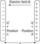
When q′ moves from location A to B in an electric field E, work is done.
U B U A = q′ Ed., work is a change in potential energy: U B U A = q′ Ed., work is a change in potential energy: U B U A =
The electrostatic potential difference (also known as the electric potential difference) is defined as the energy change per unit positive charge, or V B V A = (U B U A)/ q′ in general. It may be required to utilise the integral definition of electrostatic potential for certain configurations of electric field:

In an electric field, a test charge goes over a line integral from point A to point B along path s. (E).
In the situation of parallel plates, this is a specific case.

Where V is the potential difference between the plates, measured in units of volts (V):

The electric potential generated by a point charge (q) at a distance (r) from it equals

The issue below shows how to calculate the electric field and potential due to point charges.
Example 3: Find the following for two charges of +3 Q and – Q separated by X: (1) Where along the line does the electric field become zero? (2) Where does the electric potential zero occur? (See Illustration 11.)

Figure: The arrangement of two-point charges for the example.
The initial step is to locate the region(s) with no electric field. The electric field is a vector, and a test charge can be used to determine its direction. The figure is split into three sections. The direction of the force on the test charge between the opposed charges will be in the same direction from each charge; thus, a zero-electric field in Region II is impossible. Even though the forces from the two charges are in opposite directions on the test charge in Region I, the force, and hence the electric field, can never be zero in this region since the test charge is always closer to the largest provided charge. As a result, the only place where E can be 0 is in Region III. Set the two electric fields equal at an arbitrary location (r) to the right of – Q. Because the fields are in opposite directions, the vector sum will equal zero at this point.


If X is given, solve for r.
Potential is not a vector, so the potential is zero wherever the following equation holds:

Where r m is the distance between the test point and +3 Q, and r 2 is the distance between the test point and – Q.
This example shows how to obtain the vector quantity (E) and the scalar quantity (S) using different methods of analysis (V). It's worth noting that if the charges were both positive or both negative, a point with zero electric field between them could be found, but the potential would never be zero.
A pair of point charges separated by a distance r has an electrical potential energy of

Equipotential surfaces are those on which moving a charge from one place to another requires no effort. Equipotential surfaces are perpendicular to electric field lines at all times. Equipotential lines are two-dimensional representations of the surface's intersection with the diagram's plane. Equipotential lines for (a) a uniform field, (b) a point charge, and (c) two opposed charges are depicted in Figure.
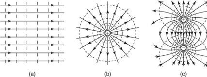
Figure: Equipotential lines for (a) a uniform electric field, (b) a point charge, and (c) a dipole.
4.4.1 Polarization:
Because it is made up of neutral atoms and molecules, the terrestrial environment is characterised by dielectric media (e.g., air and water) that are electrically neutral for the most part. When the atoms and molecules that make up such medium are exposed to an electric field, they tend to polarise, or produce electric dipole moments. Because it is made up of neutral atoms and molecules, the terrestrial environment is characterised by dielectric media (e.g., air and water) that are electrically neutral for the most part. When the atoms and molecules that make up such medium are exposed to an electric field, they tend to polarise, or produce electric dipole moments. Suppose that when a given neutral molecule is placed in an electric field, E, the centre of charge of its constituent electrons (whose total charge is  ) is displaced by a distance
  with respect to the centre of charge of its nucleus (whose charge is
  ). The dipole moment of the molecule is then
  . If there are
  such molecules per unit volume then the electric polarization
  (i.e., the dipole moment per unit volume) is given by
  . More generally,
 (496)
(496)
Where  is the average dipole moment of the
  th type of molecule in the vicinity of point, and
  is the average number of such molecules per unit volume at
  .
.
It is easily demonstrated [e.g., by integrating Equation by parts, and then comparing the result with Equation that any divergence of the polarization field,  , gives rise to a charge density,
  , in the medium. In fact,
 (497)
(497)
This density is distinguished from the charge density owing to free charges, which reflects a net excess or deficit of electrons in the medium, by bound charges (i.e., charges that emerge from the polarisation of neutral atoms). As a result, the medium's overall charge density, is
 (498)
(498)
Both terms on the right-hand side of this equation represent genuine physical charge, it should be noted. Nonetheless, distinguishing between bound and free charges is useful, especially when calculating the energy associated with electric fields in dielectric media.
Gauss' law takes the differential form
 (499)
(499)
This expression can be rearranged to give
 (500)
(500)
Where
 (501)
(501)
Is termed the electric displacement (which should not be confused with dipole moment per unit area), and has the same dimensions as P (i.e., dipole moment per unit volume). The divergence theorem tells us that
 (502)
(502)
In other words, the total free charge enclosed within a closed surface equals the flux out of that surface. The electric displacement, unlike the electric field (which is the force acting on a unit charge) or the polarisation (which is the dipole moment per unit volume), has no apparent physical meaning. This variable is only included because it allows us to calculate electric fields in the presence of dielectric materials without previously knowing the distribution of bound charges. However, this is only possible if and are connected by a constitutive relation. It is common practise to assume that the induced polarisation is proportional to the electric field, and that
 (503)
(503)
Where  is termed the medium's electric susceptibility. It follows that
 (504)
(504)
Where the dimensionless quantity
 (505)
(505)
Is known as the relative dielectric constant or relative permittivity of the medium. It follows from Equations that
 (506)
(506)
Thus, the electric fields generated by free charges in a dielectric medium are similar to those generated by the same charges in a vacuum, with the exception that they are decreased by a factor. This reduction can be explained in terms of polarisation of the medium's constituent atoms or molecules, which results in electric fields that are opposite to those of free charges. If the empty space between the electrodes is filled with a dielectric medium of dielectric constant, one obvious result is that the capacitance of a capacitor is raised by a factor (assuming that fringing fields can be neglected).
When dealing with isotropic media, it is important to understand that Equations (504)-(507) are an approximation that is generally found to hold under terrestrial settings (assuming the electric field strength does not become too great). Equation (505) applies to anisotropic media (such as crystals).
 (507)
(507)
Where  is a symmetric second-rank tensor known as the dielectric tensor. For strong electric fields, D ceases to vary linearly with E. Indeed, for sufficiently strong electric fields, neutral molecules are disrupted, and the medium becomes a plasma.
4.4.2 Boundary Conditions for E and D
When dielectric material with a non-uniform dielectric constant is present in the vicinity of a collection of free charges, the electric field no longer has the same shape as in a vacuum. Assume that space is inhabited by two dielectric mediums with uniform dielectric constants of and respectively. What are the conditions for matching on and at the interface of the two media?
Consider encapsulating a portion of the UI in a Gaussian pill-box. The pill-thickness box's is permitted to approach zero, so that its two flat faces are the only ones contributing to the outward flux. These faces are in each of the two media and run parallel to the interface. Their outward normal are (in medium 1) and (in medium 2), respectively. Equation produces if there is no free charge within the pill-box (which is fair in the limit that the box's volume approaches towards zero).
 (508)
(508)
Where  is the electric displacement in medium 1 at the interface with medium 2, et cetera. The above equation can be rewritten
 (509)
(509)
Where  is the normal to the interface, directed from medium 1 to medium 2. If the fields and charges are non-time-varying then Maxwell's equations yield
 (510)
(510)
Which gives the familiar boundary condition (obtained by integrating around a small loop that straddles the interface)
 (511)
(511)
In other words, the tangential component of the electric field and the normal component of the electric displacement are both continuous across any dielectric media interface.
4.4.3 Boundary Value Problems with Dielectrics
Consider a point charge embedded in a semi-infinite dielectric medium with dielectric constant at a distance from a planar interface separating the first medium from another semi-infinite dielectric medium with dielectric constant. Assume that the interface is parallel to the plane. We must find a solution.
 (512)
(512)
In the region  ,
,
 (513)
(513)
in the region  , and
, and
 (514)
(514)
Everywhere, subject to the following constraints at z = 0:
 (515)
(515)
 (516)
(516)
 (517)
(517)
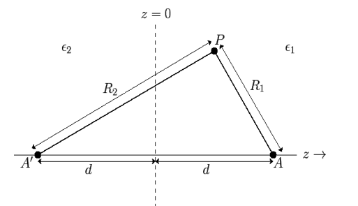
Fig: The method of images for a plane interface between two dielectric media.
In order to solve this problem, we shall employ a slightly modified form of the well-known method of images. Because  everywhere, the electric field can be written in terms of a scalar potential: that is,
  . Consider the region z>0. Let us assume that the scalar potential in this region is the same as that obtained when the whole of space is filled with dielectric of dielectric constant
  , and, in addition to the real charge
  at position
  , there is a second charge
  at the image position
  . (See Figure 1.) If this is the case then the potential at some point
  in the region
  is given by
 (518)
(518)
Where  and
and  . Here,
  ,
,  ,
, are conventional cylindrical coordinates. Note that the potential (519) is clearly a solution of Equation (513) in the region
  : that is, it satisfies
  , with the appropriate singularity at the position of the point charge
  .
.
Consider the region  . Let us assume that the scalar potential in this region is the same as that obtained when the whole of space is filled with a dielectric medium of dielectric constant
  , and a charge
  is located at the point
  . If this is the case then the potential in this region is given by
 (519)
(519)
The above potential is clearly a solution of Equation (514) in the region  : that is, it satisfies
  , with no singularities.
It's now up to you to choose and do so in such a way that the constraints (516)-(518) are met. If the scalar potential is continuous across the interface between the two mediums, the requirements (517) and (518) are obviously satisfied.
 (520)
(520)
The constraint (516) implies a jump in the normal derivative of the scalar potential across the interface. In fact,
 (521)
(521)
The first matching condition yields
 (522)
(522)
Whereas the second gives
 (523)
(523)
Here, use has been made of
 (524)
(524)
Equations (523) and (524) imply that
 (525)
(525)
 (526)
(526)
The polarization charge density is given by  , However,
  inside either dielectric, which implies that
 (527)
(527)
Except at the point charge  . Thus, there is zero bound charge density in either dielectric medium. At the interface,
  jumps discontinuously,
 (528)
(528)
This implies that there is a bound charge sheet on the interface between the two-dielectric media. In fact, it follows from Equation (498) that
 (529)
(529)
Where  is a unit normal to the interface pointing from medium 1 to medium 2 (i.e., along the positive
  -axis). Because
 (530)
(530)
In either medium, it is easily demonstrated that
 (531)
(531)
In the limit  , the dielectric
  behaves like a conducting medium (i.e.,
  in the region
  ), and the bound surface charge density on the interface approaches that obtained in the case when the plane
  coincides with a conducting surface.
The preceding logic can easily be extended to problems involving multiple point charges in the presence of numerous dielectric media with parallel plane interfaces.
Consider a second boundary value problem in which a dielectric slab with the dielectric constant is sandwiched between the planes and. Assume that this slab is put in a uniform, strength-directed electric field. Let's see how we can figure out the slab's field strength.
Because there are no free charges and this is effectively a one-dimensional problem, Equation (501) shows that the electric displacement in the dielectric slab and the surrounding vacuum is the same. In the vacuum area, whereas in the dielectric zone, As a consequence,
 (532)
(532)
In other words, polarisation charges lower the electric field inside the slab. Inside the dielectric, there is zero polarisation charge density, as previously. On both sides of the slab, however, there is a consistent bound charge sheet. It is simple to illustrate this.
 (533)
(533)
The slab behaves like a conductor in the limit, and.
Let us now generalise our findings. Consider a dielectric material with a variable dielectric constant. The medium is supposed to be finite in size and enclosed in a vacuum. As a result, as follows. Assume that this dielectric is exposed to a strong uniform -directed electric field. What is the dielectric field like inside?
We know that inside the dielectric, the electric displacement is given by Because there are no free charges and this is effectively a one-dimensional problem, we also know from Equation (501) that
 (534)
(534)
Furthermore,  as
as  . It follows that
 (535)
(535)
Thus, the electric field is inversely proportional to the dielectric constant of the medium. The bound charge density within the medium is given by
 (536)
(536)
Consider a third, and final, boundary value problem in which a dielectric sphere of radius  , and dielectric constant
  , is placed in a
  -directed electric field of strength
  (in the absence of the sphere). Let us calculate the electric field inside and around the sphere.
Because this is a static problem, we can write  . There are no free charges, so Equations (501) and (505) imply that
 (537)
(537)
Everywhere. The matching conditions (510) and (512) reduce to
 (538)
(538)
 (539)
(539)
Furthermore,
 (540)
(540)
As  : that is, the electric field asymptotes to uniform
  -directed field of strength
  far from the sphere. Here,
  ,
,  , ) are spherical coordinates centered on the sphere.
Let us search for an axisymmetric solution,  . Because the solutions to Poisson's equation are unique, we know that if we can find such a solution that satisfies all of the boundary conditions then we can be sure that this is the correct solution. Equation (538) reduces to
 (541)
(541)
Straightforward separation of the variables yields.
 (542)
(542)
Where is a non-negative integer, and are arbitrary constants, and Legendre polynomials, respectively.
The Legendre polynomials constitute a complete set of angular functions, and the and forms a full set of radial functions is simply shown. As a result, Equation (543), with and undefined, is a completely universal (single-valued) axisymmetric solution to Equation (538). The values of the and that are consistent with the boundary conditions must still be determined.
Let us divide space into the regions  and
and  . In the former region
 (543)
(543)
Where we have rejected the  radial solutions because they diverge unphysically as
  . In the latter region
 (544)
(544)
However, it is clear from the boundary condition (541) that the only non-vanishing  is
is  . This follows because
  . The boundary condition (540) [which can be integrated to give
  for a potential that is single-valued in θ ] gives
 (545)
(545)
And
 (546)
(546)
For  . Note that it is appropriate to match the coefficients of the
  because these functions are mutually orthogonal. The boundary condition (539) yields
 (547)
(547)
And
 (548)
(548)
For  . Equations (547) and (549) give
  for
for  . Equations (546) and (548) reduce to
 (549)
(549)
 (550)
(550)
The solution to the problem is therefore
 (551)
(551)
For  , and
, and
 (552)
(552)
For  .
.
Equation (552) is the potential of a uniform  -directed electric field of strength
 (553)
(553)
Note that  , provided that
  . Thus, the electric field-strength is reduced inside the dielectric sphere due to partial shielding by polarization charges. Outside the sphere, the potential is equivalent to that of the applied field
  , plus the field of an electric dipole (see Section 2.7), located at the origin, and directed along the
  -axis, whose dipole moment is
 (554)
(554)
This dipole moment can be interpreted as the volume integral of the polarization  over the sphere. The polarization is
 (555)
(555)
Because the polarization is uniform there is zero bound charge density inside the sphere. However, there is a bound charge sheet on the surface of the sphere, whose density is given by  [see Equation (530)]. It follows that
 (556)
(556)
The problem of a dielectric cavity of radius  inside a dielectric medium of dielectric constant
  , and in the presence of an applied electric field
  , parallel to the
  -axis, can be treated in much the same manner as that of a dielectric sphere. In fact, it is easily demonstrated that the results for the cavity can be obtained from those for the sphere by making the transformation
  . Thus, the field inside the cavity is uniform, parallel to the
  -axis, and of magnitude
 (557)
(557)
Note that  , provided that
  . The field outside the cavity is the original field, plus that of a
  -directed dipole, located at the origin, whose dipole moment is
 (558)
(558)
Here, the negative sign implies that the dipole points in the opposite direction to the external field.
4.4.4 Energy Density Within Dielectric Medium
Consider a system of free charges embedded in a dielectric medium. The increase in the total energy when a small amount of free charge  is added to the system is given by
 (559)
(559)
Where the integral is taken over all space, and  is the electrostatic potential. Here, it is assumed that the original charges and the dielectric are held fixed, so that no mechanical work is performed. It follows from Equation (501) that
 (560)
(560)
Where  is the change in the electric displacement associated with the charge increment. Now, the above equation can also be written
 561)
561)
Giving
 (562)
(562)
Where use has been made of the divergence theorem. If the dielectric medium is of finite spatial extent, then we can neglect the surface term to give
 (563)
(563)
This energy increment cannot be integrated unless  is a known function of
  . Let us adopt the conventional approach, and assume that
  , where the dielectric constant
  is independent of the electric field. The change in energy associated with taking the displacement field from zero to
  at all points in space is given by
 (564)
(564)
Or
 (565)
(565)
Which reduces to
 (566)
(566)
Thus, the electrostatic energy density inside a dielectric is given by
 (567)
(567)
This is a well-known result that is frequently cited in textbooks. It's vital to remember, however, that the preceding formula only applies to dielectric medium where the electric displacement, varies linearly with the electric field.
4.4.5 Force Density Within Dielectric Medium
Equation (567) was calculated via a virtual process in which actual charges are added to a fixed system of charges and dielectrics, with no mechanical work done against physical displacements. Consider a virtual process in which the physical coordinates of the charges and dielectric are virtualized at each location in space, but no free charges are added to the system. Despite the fact that it was obtained in terms of another virtual process, the energy expression (567) can still be used because we are working with a conservative system. The electrostatic force density, acting within the dielectric medium via is related to the variation in total electrostatic energy when the system undergoes a virtual displacement.
 (568)
(568)
If the medium is moving with a velocity field  then the rate at which electrostatic energy is drained from the
  and
and  fields is given by
 (569)
(569)
Consider the energy increment due to a change,  , in the free charge distribution, and a change,
  , in the dielectric constant, which are both assumed to be caused by the virtual displacement. From Equation (567),
 (570)
(570)
Or
 (571)
(571)
The first term refers to the energy increase caused by the change in dielectric constant associated with virtual displacement, whereas the second term relates to the energy increase generated by free charge displacement. The second phrase can be written in a variety of ways.
 (572)
(572)
Where surface terms have been neglected. Thus, Equation (572) implies that
 (573)
(573)
We must represent the time derivatives and in terms of the velocity field, in order to arrive at an expression for the force density. This can be accomplished by using a dielectric equation of state, which is a formula that expresses the relationship between the dielectric constant, and the mass density. Let's pretend that's a well-known function. As a consequence,
 (574)
(574)
Where
 (575)
(575)
Is the time derivative in total (i.e., the time derivative in a frame of reference that is locally co-moving with the dielectric) The dielectric's hydrodynamic continuity equation is
 (576)
(576)
Which implies that
 (577)
(577)
It follows that
 (578)
(578)
The free charge conservation equation is expressed as follows:
 (579)
(579)
As a res-ult, Equation (574) can be written as
 (580)
(580)
We get the following result by integrating the first term by parts and ignoring any surface contributions.
 (581)
(581)
Likewise,
 (582)
(582)
Thus, Equation (581) becomes
 (583)
(583)
We may determine that the force density inside the dielectric is given by comparing Equation (570) with Equation (570).
 (584)
(584)
The conventional electrostatic force density is the first term in the above equation (due to the presence of free charges). When an inhomogeneous dielectric is placed in an electric field, the second term reflects a force that appears. The electrostriction term, which is the final component, describes the force acting on a dielectric in an inhomogeneous electric field. It's worth noting that the amount of the electrostriction force density is directly proportional to the material's dielectric equation of state, as shown by. If we can integrate across a big enough piece of the dielectric that its extremities lie in a field-free zone, the electrostriction term gives zero net force acting on any finite patch of dielectric. As a result, the word is generally removed from calculations of total forces acting on dielectric bodies, because it usually has little bearing. However, if the electrostriction element is deleted, the pressure fluctuation within the dielectric is wrong, despite the fact that the total force is right.
4.4.6 Clausius-Mosotti Relation
Let's look at what a dielectric equation of state looks like in practise. Assume a dielectric medium is composed of identical molecules with a dipole moment.
 (585)
(585)
When exposed to an electric field The molecule polarizability is the name for this constant. If is the number density of such molecules, then the medium's polarisation is
 (586)
(586)
Or
 (587)
(587)
Where is the molecular weight, is Avogadro's number, and is the mass density. But how does the electric field experienced by a single molecule compare to the medium's average electric field? Because we expect the electric field to change dramatically (on atomic length scales) within the dielectric, this is not a simple question.
Assume that the dielectric is polarised by a uniform (on macroscopic length scales) mean electric field directed along the -axis. Consider one of the molecules that make up the dielectric. Let's draw a radius sphere around this specific molecule. The sphere's surface is meant to depict the dividing line between the microscopic and macroscopic ranges of processes that affect the molecule. The dielectric outside the sphere will be treated as a continuous medium, whereas the dielectric inside the sphere will be treated as a collection of polarised molecules. There is a bound surface charge of magnitude according to Equation (530).
 (588)
(588)
Is the uniform polarisation of the uniform dielectric outside the sphere, where, are conventional spherical coordinates, and is the uniform polarisation of the uniform dielectric inside the sphere. Because of this surface charge, the magnitude of at the molecule is
 (589)
(589)
Where  is an element of the surface. It follows that
 (590)
(590)
From symmetry, it can be simply proven that at the molecule. As a result of the bonded charges dispersed on the inside of the sphere's surface, the field at the molecule is
 (591)
(591)
Summing the dipole fields of the various molecules within the sphere yields the field due to these molecules. At a distance from a dipole, the electric field is
 (592)
(592)
The dipole moments of the molecules within the sphere are assumed to be the same, and the molecules are dispersed equally throughout the sphere. As a result, the value of at the molecule is affected by all of the other molecules in the sphere.
 (593)
(593)
Is zero, because, for evenly distributed molecules,
 (594)
(594)
And
 (595)
(595)
It's also simple to demonstrate that. As a result, the electric field generated by the other molecules in the sphere averages to zero at the molecule.
The net electric field experienced by a single molecule is undeniably large.
 (596)
(596)
Which is bigger than the dielectric's average electric field. According to the preceding research, this effect is due to the molecule's long-range (rather than short-range) interactions with the other molecules in the medium. Using Equation (588), as well as the definition, we arrive to
 (597)
(597)
The Clausius-Mosotti relationship is the name for this relationship. For a wide range of dielectric liquids and gases, this formula is found to be particularly useful. In addition, the Clausius-Mosotti relationship offers
 (598)
(598)
4.4.7 Dielectric Liquids in Electrostatic Fields
Consider the behaviour of a dielectric liquid that is not charged and is placed in an electrostatic field. If is the internal pressure of the liquid when it is in equilibrium with the electrostatic force density, then force balancing demands that
 (599)
(599)
It follows from Equation (585) that
 (600)
(600)
We may use this to solve the equation.
 (601)
(601)
Where 1 and 2 are two different places in the liquid. The assumption here is that the liquid has an equation of state, thus. If the liquid is fundamentally incompressible (that is, it does not change shape), then
 (602)
(602)
Finally, if the liquid follows Clausius-law, Mosotti's
 (603)
(603)
When a sphere of dielectric liquid is placed in a uniform electric field, the pressure inside the liquid takes on a constant value, according to Equations (554) and (604).
 (604)
(604)
The electrostatic forces acting on the dielectric are clearly concentrated at the sphere's edge and radially inwards, implying that the dielectric is squeezed by the external electric field. The electrostatic forces acting on a hard conducting sphere are concentrated at the sphere's edge, but they are directed radially outwards, which is a surprise conclusion. In the limit, we might expect these two scenarios to provide the same conclusion. Because a dielectric liquid is slightly compressible, it is susceptible to an electrostriction force, which prevents this from happening. In the case of a perfectly rigid body, there is no electrostriction force. In fact, Equation (585) gives the force density within a rigid dielectric (for which) with the third term (the electrostriction term) absent. The force exerted by an electric field on a rigid dielectric is easily proved to be directed outwards and approaches that exerted on a rigid conductor in the limit.
When a pair of charged (parallel plane) capacitor plates are dipped in a dielectric liquid, the liquid is drawn up to some amount between the plates, as is well known. Let's have a look at this effect. We can assume that the transition from dielectric to vacuum occurs in a continuous manner without losing generality. Consider the electrostatic pressure difference between a location just above the liquid's surface in between the plates and a position just above the liquid's surface far away from the capacitor (where). The pressure differential is calculated as follows:
 (605)
(605)
However, because in a vacuum [see Equation (599)], the Clausius-Mosotti relationship produces at both and. Equation (585) clearly shows that the electrostriction term has no effect on the line integral (606). As a consequence,
 (606)
(606)
The vacuum/dielectric contact in the region of point makes the only contribution to this integral (because is constant inside the liquid, and in the vicinity of point). Assume that the normal and tangential (to the surface) components of the electric field at point are and, respectively. We obtain by utilising the boundary conditions that and are constant over a vacuum/dielectric interface.
 (607)
(607)
Giving
 (608)
(608)
The height, that the liquid rises between the plates can be calculated by equating the electrostatic pressure difference to the hydrostatic pressure difference. At first glance, the above analysis appears to indicate that a surface force acting on the vacuum/dielectric interface in the region between the plates draws the dielectric liquid upward. In truth, this isn't the case at all. A quick look at Equation (604) reveals that this surface force is directed downwards. The force that causes the liquid to rise between the plates, according to Equation (585), is a volume force that occurs in the region of non-uniform electric field at the capacitor's base, where the field splays out between the plates. Despite the fact that we can calculate the height to which the fluid rises between the plates without using the electrostriction force, it is this force that, somewhat ironically, is responsible for maintaining the liquid against gravity.
Consider yet another conundrum using electrostatic forces in a dielectric medium. Assume two charges are implanted in a homogeneous dielectric with a dielectric constant of. Each charge generates an electric field that is identical to that in a vacuum, except that it is lowered by a fraction. As a result, we anticipate that the force exerted by one charge on another will be the same as in a vacuum, except that it will be reduced by a factor. Let's have a look at how this force decrease occurs. Consider the following scenario. Assume we have a parallel plate capacitor with a solid dielectric block between the plates. Assume that the faces of the block and each of the capacitor plates have a small vacuum gap between them. Let the surface charge densities on each capacitor plate be and the bound charge densities that arise on the outer edges of the dielectric block between them be. On each plate, the two layers of bound charge produce equal and opposing electric fields, cancelling each other's effects. Thus, when a dielectric slab is placed between two capacitor plates, there appears to be no change in the force exerted by one on the other from the standpoint of electrical interaction alone (assuming that remains constant during this process). That is, the attractive force per unit area remains constant.
 (609)
(609)
However, when a capacitor is submerged in a dielectric liquid, the force produced by one plate on another is found to fall to
 (610)
(610)
The seeming paradox can be explained by considering the difference in liquid pressure between the plates in the field-filled space and the field-free zone outside the capacitor. In the case of the solid dielectric stated previously, internal elastic forces balance the pressure difference, but in the case of the liquid dielectric, the pressure difference is communicated to the plates. Equation can be used to calculate the pressure differential between a position on the inside surface of one of the capacitor plates and a position on the same plate's exterior surface (607). If we ignore end effects, the electric field in the region between the plates is normal to the plates and zero everywhere else. As a result, the plate/dielectric contact in the area of point is the only source of contribution to the line integral (607) We may see from Equation (609), that
 (611)
(611)
In the absence of dielectric, what is the normal field strength between the plates? The net attractive force per unit area is equal to the sum of this pressure force and the purely electrical force (610)
 (612)
(612)
Interacting with the plates. As a result, any reduction in the forces exerted by charges on one another when submerged or embedded in a dielectric medium can only be explained in terms of mechanical forces transferred between these charges by the medium.
4.5.1 Clausius-Mosotti relation:
The Clausius-Mosotti connection [1] [2] in physics links a dielectric's relative permittivity r to the polarizability of the atoms or molecules that make up the dielectric. Relative permittivity is a bulk (macroscopic) property of matter, while polarizability is a microscopic characteristic; thus, the relationship connects a directly observable macroscopic feature with a tiny molecular property.
For dielectric matter made up of atoms or (non-polar) molecules, the Clausius-Mosotti equation is used.

Where 0 denotes the electric constant (vacuum permittivity) and N denotes the number density (number of atoms or molecules per volume).
A dielectric's index of refraction, n, is given by

Where we used that the relative magnetic permeability r is fairly close to unity for most dielectric materials. The Lorentz-Lorenz relation is obtained by substituting this value of n.

4.5.2 Lorentz-Lorenz relation:
The Lorentz-Lorenz relation is a physics equation that describes the relationship between the index of refraction n and the density of a dielectric (non-conducting matter),

The polarizability of the molecules that make up the dielectric determines the proportionality constant K.
The relationship is named after Hendrik Antoon Lorentz, a Dutch physicist, and Ludvig Valentin Lorenz, a Danish physicist.
The proportionality factor K (m3/kg) for a molecular dielectric made up of a single type of non-polar molecules is,

Where M (g/mol) is the molar mass (previously known as molecular weight) and PM (m3/mol) is the molar mass (previously known as molecular weight) in SI units:

NA is Avogadro's constant, is one molecule's molecular polarizability, and 0 is the electric constant (permittivity of the vacuum). The molecular polarizabilities are assumed to be additive in this expression for PM; if this is not the case, the expression can still be employed if is replaced by an effective polarizability. The factor 1/3 is based on the idea that a single molecule inside the dielectric experiences a spherical field from the surrounding media. Because / 0 has the dimension volume, K has the dimension volume per mass.
In non-rationalized centimeter-gram-second units (Gaussian units):

A temperature-dependent contribution owing to dipole alignment must be added to K for polar molecules.
The Lorentz-Lorenz law is derived from the Clausius-Mosotti relation, which states that the index of refraction n is approximately equal to the square root of the static relative permittivity (formerly known as static relative dielectric constant) r (for non-conducting materials and long wavelengths).

The relative permeability r equals unity in this relationship, which is a plausible assumption for diamagnetic and paramagnetic matter but not for ferromagnetic materials.
4.6.1 How are polarizabilities measured experimentally?
Most typical spectroscopies that yield a whole spectrum, a tensor, or a scalar value have a dedicated apparatus that is reasonably self-contained and non-standard. Benchtop FT-IR spectrometers, for example, provide (linear) IR spectra, while FT-NMR spectrometers (capable of multiple experiments) provide NMR chemical shifts, and so on. The (electric dipole) polarizability, which "is defined as the ratio of the induced dipole moment pp of (a molecule) to the electric field EE that produces this dipole moment" and is important for designing optical materials, is one spectroscopic property that serves as a benchmark for electronic structure theory and is important for designing optical materials:

This refers to how easy it is to move a system's charge density or electron cloud around physically. It's a symmetric rank-2 tensor, to put it another way:

Because the supplied electric field may have three distinct Cartesian coordinates and the system being measured may have an anisotropic response to it Calculating the tensor can take a long time in some circumstances, although the process is well-understood and there are standardised ways for doing it. However, I'm not sure how it's measured in a lab setting. The Lorentz-Lorenz equation exists (rearranged),

It connects a system's or medium's polarizability to its refractive index nn. There is also the Clausius-Mosoti relation, which relates the dielectric constant ϵϵ to the polarizability, as the refractive index and (complex) dielectric constant is related:
n∝
This leads me to believe that using a refractometer to determine the refractive index is the preferred method of determining polarizability.
Is the refractive index the most prevalent way of determining polarizability experimentally? Is it possible to test it directly, or does it have to be through a relationship like the ones listed above?
- Is this relationship valid for both directed (anisotropic) and averaged (isotropic) polarizabilities?
- The refractive index and polarizability are qualities that are frequency dependent. What is the method for determining static (frequency-independent) polarizability? Is it even possible to do so without using extrapolation from a large number of frequency-dependent data points?
4.6.2 Polarizability:
Polarizability helps us better understand how nonpolar atoms and molecules interact with other electrically charged species like ions and polar molecules with dipole moments.
Introduction
In their electron clouds, neutral nonpolar substances exhibit spherically symmetric groupings of electrons. Their electron clouds can be altered in the presence of an electric field (Figure 11). The polarizability of an atom or molecule determines how easily it can be distorted. The nonpolar molecule or atom gains a dipole moment as a result of the generated distortion of the electron cloud. The following equation relates the induced dipole moment to the polarizability of the molecule or atom and the strength of the electric field:

Where E signifies the electric field strength and is the polarizability of the atom or molecule in C m2V-1 units.
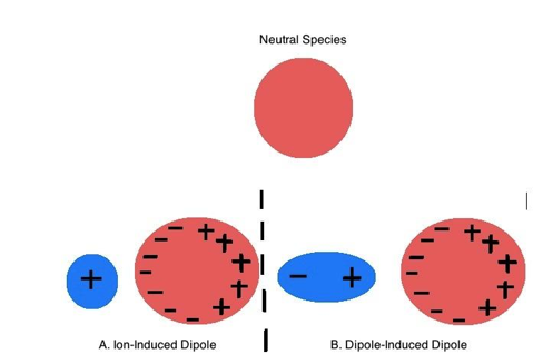
Figure: A neutral nonpolar species’ electron cloud is distorted by A.) an Ion and B.) a polar molecule to induce a dipole moment.
Polarizability is related to the interaction of electrons with the nucleus in general. The number of electrons in a molecule influences how tightly the nuclear charge can govern the charge distribution overall. Because there is a significant interaction between the few electrons in the atoms' orbitals and the positively charged nucleus, atoms with fewer electrons will have smaller, denser electron clouds. Atoms with fewer electrons have less shielding, resulting in a stronger interaction between the outside electrons and the nucleus. Because the electrons in these tiny atoms are closely bound, they are not easily polarised by external electric fields. Large atoms with numerous electrons, such as negative ions with extra electrons, on the other hand, are easily polarised. These atoms have huge atomic radii and dispersed electron clouds, which limit the interaction of their exterior electrons with the nucleus.
Factors that Influence Polarizability
The following is the link between polarizability and electron density, atomic radii, and molecule orientation:
1. The nuclear charge has less control over charge distribution as the number of electrons increases, resulting in increasing polarizability of the atom.
2. The larger the distance between electrons and nuclear charge, the less control the nuclear charge has on the charge distribution, and hence the larger the atom's polarizability.
3. Except for molecules that are tetrahedral, octahedral, or icosahedral, polarizibility can be affected by molecular orientation in relation to an electric field (labelled Orientation-dependent) (labelled Orientation-independent). This is especially true for unsaturated compounds like 2,4-hexadiene, which have areas of electron-dense regions. When the electric field is applied parallel to the molecule rather than perpendicular to the molecule, the greatest polarizability is achieved.
Polarizability Influences Dispersion Forces
The weakest intermolecular force is the dispersion force. It's an attracting force that emerges from nonpolar molecules or species' transient dipole moments. When there are instantaneous variations in the electron clouds of nonpolar species, these temporary dipole moments occur. Surrounding molecules are affected by these brief dipole moments, resulting in a chain reaction that produces weak, dipole-induced dipole interactions. The attractive dispersion forces are created by the accumulated dipole-induced dipole interactions. When the temperature is low enough, dispersion forces cause nonpolar substances to condense into liquids and freeze into solids.
Polarizability has the following effects on dispersion forces:
1. The dispersion forces become stronger as polarizability increases. As a result, molecules attract one other more strongly, and the melting and boiling temperatures of covalent substances rise as molecular mass increases.
2. Polarizability has an impact on dispersion forces due to the molecular shape of the molecules involved. Elongated molecules have more easily transported electrons, which increases their polarizability and strengthens the dispersion forces (Figure 22). Small, compact, symmetrical molecules, on the other hand, are less polarizable and have less dispersion forces.
Graph: (top) A more compact and less polarizable molecule is neopentane, which is an isomer of n-pentane. (At the bottom) An example of an elongated molecule that is more easily polarised is n-Pentane.
The following equation, which may be used to measure the interaction between two like nonpolar atoms or molecules, shows the link between polarizability and dispersion forces:

Where
- r is the distance between the atoms or molecules,
- I is the first ionization energy of the atom or molecule, and
- α is the polarizability constant expressed in units of m3.
This expression of ααis related to α′α′by the following equation:

To quantify the interaction between unlike atoms or molecules (A and B) the Equation becomes:

4.6.3 Dipole Moment:
Molecular Dipole Moments
You already know how to find the dipole moments of simple diatomic molecules. The three-dimensional geometry and symmetry of increasingly complex molecules with polar covalent connections dictate whether there is a net dipole moment. Dipole moments are vectors in mathematics; they have both a magnitude and a direction. The vector sum of the dipole moments of the individual bonds in a molecule is thus the dipole moment of the molecule. There is no net dipole moment if the individual bond dipole moments cancel out. CO2, a linear molecule, is an example of this. Despite the fact that each C–O bond in CO2 is polar, tests reveal that the CO2 molecule does not have a dipole moment. The two C–O bond dipoles in CO2 cancel because their magnitudes are equivalent and they are orientated at 180 degrees to each other. As a result, despite having a significant charge separation, the CO2 molecule has no net dipole moment. The dipole moments do not cancel each other because the H2O molecule is not linear (part (b) in Figure); it is bent in three-dimensional space. As a result, a molecule like H2O has a net dipole moment. The oxygen, the more electronegative atom, should have the highest concentration of negative charge, whereas the two hydrogens should have the highest concentration of positive charge. H2O can hydrogen-bond to other polarised or charged species, including other water molecules, because of its charge polarisation.
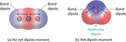
For two triatomic molecules with different structures, the individual bond dipole moments are added together to give an overall Molecular Dipole Moment. (a) The C–O bond dipoles in CO2 have the same amplitude but are orientated in different directions (at 180°). CO2 has no net dipole because their vector total is zero. (b) The O–H bond dipoles in H2O are also of similar amplitude, but they are orientated at 104.5 degrees to each other. As a result, the vector total is greater than zero, indicating that H2O has a net dipole moment.
Figure shows several instances of molecules having polar links. Individual bond dipole moments cancel out completely in extremely symmetrical molecular geometries (most notably tetrahedral and square planar, trigonal bipyramidal, and octahedral), and there is no net dipole moment. Although the atoms bound to carbon in a molecule like CHCl3 are tetrahedral, they are not identical. As a result, the dipole moments of the bonds cannot cancel each other, and the molecule has a dipole moment. The bond dipole moments of molecules with V-shaped, trigonal pyramidal, seesaw, T-shaped, and square pyramidal geometries cannot cancel each other due to the arrangement of the bonds. As a result, molecules with certain geometries always have a dipole moment greater than zero.

Molecules with Polar Bonds. The bond dipole moments of individual bonds are shown in red. Some molecules with polar bonds have a net dipole moment (HCl, CH2O, NH3, and CHCl3) due to their various three-dimensional structures, but others do not (HCl, CH2O, NH3, and CHCl3) because the bond dipole moments cancel (BCl3, CCl4, PF5, and SF6).
References:
- A 1:1 ratio of each salt was used as a salt mixture.
- Bockris, J.O., Reddy, A. K. N. Modern Electrochemistry 1: Ionics. 2003. 2nd ed. Springer
- Hamer, W. J. The Structure of Electrolytic Solutions. In: Stokes, R. H. Mobility of Ions in Relation to Viscosity. New York: John wiley & sons, Inc, 1959. Pp. 289-307
- P.W. Atkins, Physical Chemistry. 1998, 6th ed. Oxford University Press
- Misra, P. P., Das, N. C., Das, P.B., Cellular and Molecular Life Sciences., 1979, 35 (6): 724- 725
- Mendolia, M.S. Farrington, G. C., Chem. Mater. 1993, 5, 174- 181
- R. W. Impey, P. A. Madden, I. R. McDonald, J. Phys. Chem., 1983, 87, 5071-5083
- S. H. Lee, P. T. Cummings, J. Chem. Phys., 2000, 112, 864- 869
- D. R. Lide, Handbook of Physicas and Chemistry, 2000, 81st ed. CRC Press
- R. Buchner, Priv- Doz, F. Samani, P. M. May, P, Sturm, G. Hefter, Chem. Phys. Chem., 2002, 4 (4), 373 - 378