Unit - 2
Magnetic Field
2.1.1 Magnetic Force
Magnetic Force is caused by the motion of charges. Two objects containing charge with the same direction of motion have a magnetic attraction force between them. Similarly, objects with charge moving in opposite directions have a repulsive force between them.
Consider two objects. The magnitude of the magnetic force between them depends on how much charge is in how much motion in each of the two objects and how far apart they are. The direction of the force depends on the relative directions of motion of the charge in each case.
F = qv × B
F = qvB sinθ
2.1.2 Lorentz Force
The Lorentz Force is the force on a charged particle due to electric and magnetic fields. A charged particle in an electric field will always feel a force due to this field, of magnitude F, equals, q, E, F=qE. A charged particle in a magnetic field will only feel a force due to the magnetic field if it is moving with a component of its velocity perpendicular to the field. If it moves parallel to the magnetic field, it experiences no force. These two forces are often studied separately, but the sum of these two forces creates a force that we call the Lorentz force.
The flow of an electric current down a conducting wire is ultimately due to the motion of electrically charged particles (in most cases, electrons) through the conducting medium. It seems reasonable, therefore, that the force exerted on the wire when it is placed in a magnetic field is really the resultant of the forces exerted on these moving charges. Let us suppose that this is the case.
Let A be the (uniform) cross-sectional area of the wire, and let n be the number density of mobile charges in the conductor. Suppose that the mobile charges each have charge q and velocity v. We must assume that the conductor also contains stationary charges, of charge –q and number density n(say), so that the net charge density in the wire is zero. In most conductors, the mobile charges are electrons and the stationary charges are atomic nuclei. The magnitude of the electric current flowing through the wire is simply the number of coulombs per second which flow past a given point. In one second, a mobile charge moves a distance v, so all of the charges contained in a cylinder of cross-sectional area A and length v flow past a given point. Thus, the magnitude of the current is qnAv.
The direction of the current is the same as the direction of motion of the charges, so the vector current is F = qnAv
The force per unit length acting on the wire is
 ………… (1)
However, a unit length of the wire contains nA moving charges. So, assuming that each charge is subject to an equal force from the magnetic field, the force acting on an individual charge is
 ………… ( 2)
We can combine this with Eq. (2) to give the force acting on a charge q moving with velocity v in an electric field E and a magnetic field B:
 ………… ( 3)
This is called the Lorentz force law, after the Dutch physicist Hendrik Antoon Lorentz who first formulated it. The electric force on a charged particle is parallel to the local electric field. The magnetic force, however, is perpendicular to both the local magnetic field and the particle's direction of motion. No magnetic force is exerted on a stationary charged particle.
Lorentz force explains the mathematical equations along with the physical importance of forces acting on the charged particles that are traveling through the space containing electric as well as the magnetic field. This is the importance of the Lorentz force.
The following are the applications of Lorentz force:
- Cyclotrons and other particle accelerators use Lorentz force.
- A bubble chamber uses Lorentz force to produce the graph for getting the trajectories of charged particles.
- Cathode ray tube televisions use the concept of Lorentz force to deviate the electrons in a straight line so land on specific spots on the screen.
Key Takeaways
- Magnetic Force is caused by the motion of charges.
- The Lorentz Force is the force on a charged particle due to electric and magnetic fields.
- It is given by

- Lorentz force explains the mathematical equations along with the physical importance of forces acting on the charged particles that are traveling through the space containing electric as well as the magnetic field.
The Biot Savart Law is an equation describing the magnetic field generated by a constant electric current. It relates the magnetic field to the magnitude, direction, length, and proximity of the electric current. Biot–Savart law is consistent with both Ampere’s circuital law and Gauss’s theorem. The Biot-Savart law is fundamental to magnetostatics, playing a role similar to that of Coulomb’s law in electrostatics.
The Biot-Savart law can be stated as:
Hence  or
or  ……….(1)
Where, k is a constant, depending upon the magnetic properties of the medium and system of the units employed.
In the SI system of unit,
 ……….(2)
Therefore, the final Biot-Savart law derivation is,
 ……….(3)
Derivation
Let us consider a long wire carrying a current I and also consider a point p in the space. The wire is presented in the picture below, by red colour.
Let us also consider an infinitely small length of the wire dl at a distance r from the point P as shown. Here, r is a distance-vector which makes an angle θ with the direction of current in the infinitesimal portion of the wire.
If you try to visualize the condition, you can easily understand the magnetic field density at point P due to that infinitesimal length dl of the wire is directly proportional to current carried by this portion of the wire.
As the current through that infinitesimal length of wire is the same as the current carried by the whole wire itself, we can write,
 ……….(4)
The magnetic field density at that point P due to that infinitesimal length dl of wire is inversely proportional to the square of the straight distance from point P to the center of dl. Mathematically we can write this as,
 ……….(5)
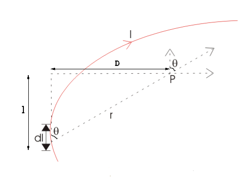
Figure 1: Biot-Savart law
As θ be the angle between distance vector r and direction of current through this infinitesimal portion of the wire, the component of dl directly facing perpendicular to the point P is dlsinθ,
Hence,  ……….(6)
Now, combining these three statements, we can write,
 ……….(7)
This is the basic form of Biot Savart’ s Law
Now, putting the value of constant k (which we have already introduced at the beginning of this article) in the above expression, we get

 ……….(8)
Here, μ0 used in the expression of constant k is absolute permeability of air or vacuum and its value is 4π 10-7 Wb/ A-m in the SI system of units. μr of the expression of constant k is the relative permeability of the medium.
Now, flux density(B) at the point P due to the total length of the current-carrying conductor or wire can be represented as,
 ……….(9)
If D is the perpendicular distance of the point P from the wire, then
 ……….(10)
Now, the expression of flux density B at point P can be rewritten as,

Again  ……….(11)
As per the figure above,
Therefore,  ……….(12)
Finally, the expression of B comes as,


 ……….(13)
This angle θ depends upon the length of the wire and the position of the point P. Say for a certain limited length of the wire, angle θ as indicated in the figure above varies from θ1 to θ2. Hence, magnetic flux density at point P due to the total length of the conductor is,


 ……….(14)
Let’s imagine the wire is infinitely long, then θ will vary from 0 to π that is θ1 = 0 to θ2 = π. Putting these two values in the above final expression of Biot Savart law, we get,
 ……….(15)
This is nothing but the expression of Ampere’s Law.
Key Takeaways
- The Biot Savart Law is an equation describing the magnetic field generated by a constant electric current.
- It relates the magnetic field to the magnitude, direction, length, and proximity of the electric current.
- The Biot-Savart law can be stated as:

Numerical: A short wire of length 1.0 cm carries a current of 2.0 A in the vertical direction (as shown in figure). The rest of the wire is shielded so it does not add to the magnetic field produced by the wire. Calculate the magnetic field at point P, which is 1 meter from the wire in the x-direction.
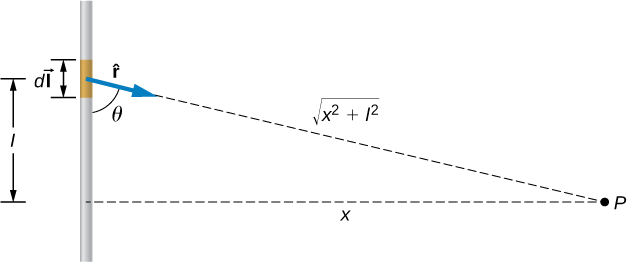
Sol:
The angle between Δl⃗ and  is calculated from trigonometry, knowing the distances l and x from the problem:
θ=tan−1(1m/0.01m)=89.4o.
The magnetic field at point P is calculated by the Biot-Savart law


2.3.1 Magnetic Field on the Axis of a Current Carrying Circular Loop
Firstly we shall evaluate the magnetic field due to a circular coil along its axis.
We assume that the current I is steady and that the evaluation is carried out in free space.
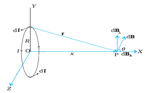
Figure 2: Magnetic field on the axis of a current carrying circular loop of radius R.
Figure depicts a circular loop carrying a steady current I. The loop is placed in the y-z plane with its centre at the origin O and has a radius R. The x-axis is the axis of the loop. Let x be the distance of P from the centre O of the loop.
Consider a conducting element dl of the loop. This is shown in Figure. The magnitude dB of the magnetic field due to dl is given by the Biot-Savart law
 …… (1)
Now r2 = x2 + R2. Further, any element of the loop will be perpendicular to the displacement vector from the element to the axial point. For example, the element dl in is in the y-z plane, whereas, the displacement vector r from dl to the axial point P is in the x-y plane. Hence |dl × r|=r dl. Thus,

The direction of dB is shown in figure. It is perpendicular to the plane formed by dl and r. It has an x-component dBx and a component perpendicular to x-axis, dB⊥. When the components perpendicular to the x-axis are summed over, they cancel out and we obtain a null result.
For example, the dB⊥ component due to dl is cancelled by the contribution due to the diametrically opposite dl element, shown in figure. Thus, only the x-component survives. The net contribution along x-direction can be obtained by integrating dBx = dBcosθ over the loop.
 …… (3)
Thus from (2) and (3)
 …… (4)
The summation of elements dl over the loop yields 2πR, the circumference of the loop. Thus, the magnetic field at P due to entire circular loop is
 …… (5)
As a special case of the above result, we may obtain the field at the centre of the loop. Here x = 0, and we obtain,
 …… (6)
The direction of the magnetic field is given by right-hand thumb rule. Curl the palm of your right hand around the circular wire with the fingers pointing in the direction of the current. The right-hand thumb gives the direction of the magnetic field.
2.3.2 Current loop as a magnetic dipole and its dipole moment
Consider the elementary magnetic element: the current loop. We know that the magnetic field (at large distances) due to current in a circular current loop is very similar in behaviour to the electric field of an electric dipole.
The magnetic field on the axis of a circular loop, of a radius R, carrying a steady current I. The magnitude of this field is (Using equation (4))
 …… (1)
And its direction is along the axis and given by the right-hand thumb rule . Here, x is the distance along the axis from the centre of the loop. For x >> R, we may drop the R2 term in the denominator. Thus
 …… (2)
The area of the loop A = πR2. Thus
 …… (3)
The magnetic moment m to have a magnitude IA,
m = IA. Hence
 …… (4)
The expression of Eq (4) is very similar to an expression obtained for the electric field of a dipole. The similarity may be seen if we substitute,
μ0  1/Ɛ0
1/Ɛ0
m pe (electrostatic dipole)
B E (electrostatic field)
We then obtain,
Which is precisely the field for an electric dipole at a point on its axis.
 …… (5)
It can be shown that the above analogy can be carried further. We had found that the electric field on the perpendicular bisector of the dipole is given by
 …… (6)
Where x is the distance from the dipole. If we replace μ0  1/Ɛ0
1/Ɛ0
And m pe in the above expression, we obtain the result for B for a point in the
Plane of the loop at a distance x from the centre. For x >>R,
 …… (7)
The results given by Equations (4) and (7) become exact for a point magnetic dipole.
The results obtained above can be shown to apply to any planar loop: a planar current loop is equivalent to a magnetic dipole of dipole moment m = I A, which is the analogue of electric dipole moment p.
Note, however, a fundamental difference: an electric dipole is built up of two elementary units — the charges (or electric monopoles). In magnetism, a magnetic dipole (or a current loop) is the most elementary element. The equivalent of electric charges, i.e., magnetic monopoles, are not known to exist.
We have shown that a current loop (i) produces a magnetic field and behaves like a magnetic dipole at large distances, and (ii) is subject to torque like a magnetic needle. This led Ampere to suggest that all magnetism is due to circulating currents. This seems to be partly true and no magnetic monopoles have been seen so far. However, elementary particles such as an electron or a proton also carry an intrinsic magnetic moment, not accounted by circulating currents.
Key Takeaways
- As a special case of the above result, we may obtain the field at the centre of the loop. Here x = 0, and we obtain,

- The direction of the magnetic field is given by right-hand thumb rule.
- An expression obtained for the magnetic field of a dipole

- The results obtained above can be shown to apply to any planar loop: a planar current loop is equivalent to a magnetic dipole of dipole moment m = I A, which is the analogue of electric dipole moment p.
2.4.1 Ampere’s Law
Ampere’s circuital law (ACL) relates current to the magnetic field associated with the current. The magnetic field in space around an electric current is proportional to the electric current which serves as its source, just as the electric field in space is proportional to the charge which serves as its source.

Figure 3: Ampere’s circuital law
Ampere's Law states that
The integral around a closed path of the component of the magnetic field tangent to the direction of the path equals μ0 times the current intercepted by the area within the path.
 = μ0I ………..(1)
Ampere's Law tells that for any closed loop path, the sum of the length elements times the magnetic field in the direction of the length element is equal to the permeability times the electric current enclosed in the loop.
In order to apply Ampère’s Law
All currents have to be steady (i.e.do not change with time)
Only currents crossing the area inside the path are taken into account and have some contribution to the magnetic field
The total magnetic circulation is zero only in the following cases:-
- The enclosed net current is zero
- The magnetic field is normal to the selected path at any point
- The magnetic field is zero
Finally, be aware that the form of Ampère’s Law addressed here applies to magnetostatics only. In the presence of a time-varying electric field, the right side of ACL includes an additional term known as the displacement current.
2.4.2 Application
(1) Solenoid
Consider a long solenoid. Long solenoid mean that the solenoid’s length is large compared to its radius. It consists of a long wire wound in the form of a helix where the neighbouring turns are closely spaced. So each turn can be regarded as a circular loop. The net magnetic field is the vector sum of the fields due to all the turns. Enamelled wires are used for winding so that turns are insulated from each other.
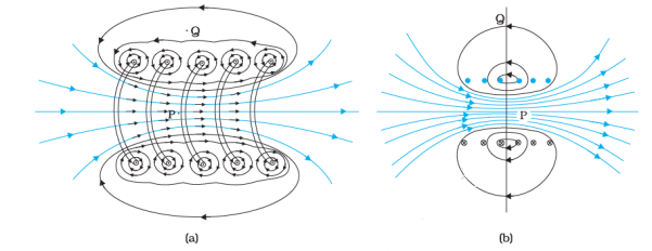
Figure 4: (a) The magnetic field due to a section of the solenoid which has been stretched out for clarity. Only the exterior semi-circular part is shown. (b) The magnetic field of a finite solenoid.
Figure displays the magnetic field lines for a finite solenoid. It is clear from the circular loops that the field between two neighbouring turns vanishes. We can see that the field at the interior mid-point P is uniform, strong and along the axis of the solenoid.
The field at the exterior mid-point Q is weak and moreover is along the axis of the solenoid with no perpendicular or normal component. As the solenoid is made longer it appears like a long cylindrical metal sheet. The field outside the solenoid approaches zero. We shall assume that the field outside is zero. The field inside becomes everywhere parallel to the axis.

Figure 5: Magnetic field of a very long solenoid
Consider a rectangular loop abcd. Along cd the field is zero. Along transverse sections bc and ad, the field component is zero. Thus, these two sections make no contribution.
Let the field along ab be B. Thus, the relevant length of the loop is, L = h.
Let n be the number of turns per unit length, then
The total number of turns is = nh
The enclosed current is, Ie = I (nh) ……… (1)
Where I is the current in the solenoid.
From Ampere’s circuital law
BL = μ0Ie ……… (2)
Bh = μ0I(nh) ……… (3)
B = μ0nI ……… (4)
The direction of the field is given by the right-hand rule. The solenoid is commonly used to obtain a uniform magnetic field.
(2) Toroid
The toroid is a hollow circular ring on which a large number of turns of a wire are closely wound. It can be viewed as a solenoid which has been bent into a circular shape to close on itself. It is shown in Figure below.

Figure 6: Toroid carrying current I.
Current I is flowing through it. We shall see that the magnetic field in the open space inside (point P) and exterior to the toroid (point Q) is zero. The field B inside the toroid is constant in magnitude for the ideal toroid of closely wound turns.

Figure 7: A sectional view of the toroid.
The direction of the magnetic field inside is clockwise as per the right-hand thumb rule for circular loops. Three circular Amperian loops 1, 2 and 3 are shown by dashed lines. By symmetry, the magnetic field should be tangential to each of them and constant in magnitude for a given loop. The circular areas bounded by loops 2 and 3 both cut the toroid: so that each turn of current carrying wire is cut once by the loop 2 and twice by the loop 3.
Let the magnetic field along loop 1 be B1 in magnitude.
Ampere’s circuital law
L = 2πr1.
However, the loop encloses no current, so Ie = 0. Thus,
B1 (2πr1) = μ0(0)
B1 = 0
Thus, the magnetic field at any point P in the open space inside the toroid is zero.
We shall now show that magnetic field at Q is likewise zero. Let the magnetic field along loop 3 be B3. Once again from Ampere’s law L = 2πr3. However, from the sectional cut, we see that the current coming out of the plane of the paper is cancelled exactly by the current going into it. Thus,
Ie= 0, and B3 = 0.
Let the magnetic field inside the solenoid be B. We shall now consider the magnetic field at S.
Thus again by Ampere’s law
We find,
L = 2πr
The current enclosed Ie is (for N turns of toroidal coil) = NI
B (2πr) = μ0NI
B = μ0NI/2πr
Compare the two results: for a toroid and solenoid.
Let r be the average radius of the toroid and n be the number of turns per unit length. Then
N = 2πr n = (average) perimeter of the toroid × number of turns per unit length and thus,
B = μ0 nI
This is the result for the solenoid.
In an ideal toroid the coils are circular. In reality the turns of the toroidal coil form a helix and there is always a small magnetic field external to the toroid.
(3) Helmhotz Coil
A Helmholtz coil is a parallel pair of identical circular coils spaced one radius apart and wound so that the current flows through both coils in the same direction. This winding results in a uniform magnetic field between the coils with the primary component parallel to the axes of the two coils.
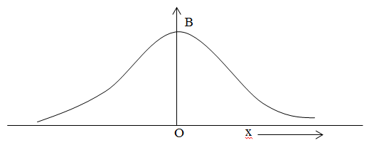
Figure 8: Graph between B and x
Consider a circular current carrying coil carrying current I. The magnetic field at any axis at a distance x from the centre of the coil is

From equation-(i) it is seen that the magnetic field varies with varying a distance from centre to at any point along the axis. It is seen that from above graph the magnetic field due to single circular current carrying coil cannot be uniform.
Helmholtz found that when two identical co-axial circular current carrying coil carrying current in same direction are placed at a distance which is equal to the radius of the coil, the magnetic field due to coil is uniform. It is due to magnetic field of one coil balanced by the magnetic field of other coil. i.e. if the magnetic field of one coil is decreased then the magnetic field of other coil is increased and the net magnetic field remains constant.
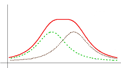
Figure 9: Net magnetic field remains constant
Magnitude of B:
The magnetic field due to circular current carrying coil having n number of circular turns carrying current I at a distance x from the centre of the coil is

The rate of increasing or decreasing of magnetic field is given by differentiating b with respect to x, we get


Since the magnetic field is uniform then dB/dx is constant. Now


The magnitude of magnetic field is maximum in midway of the space between two current carrying coil.
We know that

If  then
then


Total magnetic field is


Key Takeaways
- Ampere's Law states that, The integral around a closed path of the component of the magnetic field tangent to the direction of the path equals μ0 times the current intercepted by the area within the path.
 = μ0I
= μ0I
- Solenoid consists of a long wire wound in the form of a helix where the neighbouring turns are closely spaced. So each turn can be regarded as a circular loop.
- The toroid is a hollow circular ring on which a large number of turns of a wire are closely wound. It can be viewed as a solenoid which has been bent into a circular shape to close on itself.
- A Helmholtz coil is a parallel pair of identical circular coils spaced one radius apart and wound so that the current flows through both coils in the same direction.
Numerical: A long solenoid is fabricated to closely winding wire of radius 0.5mm over a cylindrical frame, so that the successive turns nearly touch each other. The magnetic field at the centre of solenoid, if it carries a current of 5A is?
A) 4π × 10-2 T B) 2π × 10-3 T C) 5π × 10-4 T D) 4π × 10-5 T
Solution:
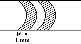
Figure 10: Long solenoid
The turns of wire on the solenoid are shown in figure.
Number of turns in 1mm = 1,
n = 1000 turns / m
Therefore, B = μ0nI = 4π × 10−7 × 103 × 5 = 2π × 10−3 T
The static electric field E(x; y; z) such as the field of static charges obeys equations
∇. E = ρ ………..(3.2a)
 = 0 ………..(3.2b)
The static magnetic field B(x; y; z) such as the field of steady currents obeys different equations
 =0 ………..(3.2c)
 J ………..(3.2d)
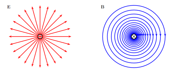
Figure 11: Electric and Magnetic Fields
Due to this difference, the magnetic field of long straight wire looks quite different from the electric field of a point charge or a linear charge.
Later in these notes we will derive equations (3.2c) and (3.2d) from the Biot Savart Law.
Let us explore some of their consequences. The zero-divergence equation (3.2c) is valid for any magnetic field, even if it is time-dependent rather than static. Physically, it means that there are no magnetic charges, otherwise we would have ∇.B  mag instead of ∇ B= 0.
Consequently, the magnetic field lines never begin or end anywhere in space; instead they form closed loops or run from in infinity to in infinity.
The integral form of eq. (3.2c) follows by the Gauss theorem: the magnetic flux through any closed surface is zero

Consequently, any open surfaces S1,S2,……..spanning the same loop L have the same magnetic flux through them, for example
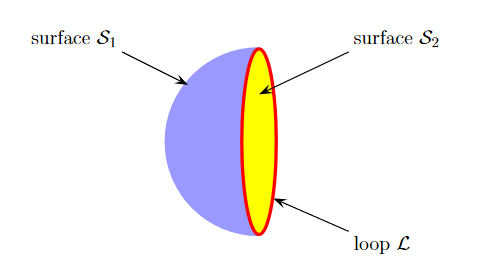
Figure 12: Open Surface

We shall this identity very useful for stating the Faraday's Law of magnetic induction.
Now consider the curl equation
 J
J
Which is the differential form of the Ampere's Law. The integral form of the Ampere's Law obtains by the Stokes' theorem: For any closed loop L and any surface S spanning that loop,
 ………..(3.2e)
Where Inet [through L] is the net electric current flowing through the loop L. The integral form (3.2e) of the Ampere's Law is particularly convenient when the current flows through a wire or several wires; in this case all we need is to check which wire goes through the loop L and which does not, then add up the currents in the wires that do go through L and mind their directions. But it is also convenient for the volume currents flowing through thick conductors or for current sheets flowing on surfaces.
As we know that the Ampere's Law applies only to the magnetic fields of steady currents. Otherwise, we need to use the more general Maxwell {Ampere Law, with an extra term for the time-dependent electric field.
For simplicity we say that the original Ampere's Law is simply mathematically inconsistent unless the electric current has zero divergence,∇J= 0.Indeed, the left hand side of the curl equation  J always have zero divergence.
∇. ( ) = 0
) = 0
So we cannot have ( ) =
) =  J unless the RHS has zero divergence as well,
∇.J= 0. As to the integral form (3.2e) of the Ampere's Law, we need a divergence-less current density J to make sure that the net current through the loop L is the same for any surface S spanning the loop; otherwise we simply cannot de ne the net current through L
Derivation of divergence and curl of magnetic field
In general, when dealing with a current density J(x’) instead of a current I so (equation 1 of article 3.1) for the magnetic induction B(x) takes the form
 ……….(1)
Equation (1) can be expressed differently, since
 ……….(2)
But since


 ……….(3)
We get
 ……….(4)
If we set  =1/
=1/ and a=J(x’), with
  J(x’)=0, since the current density is independent of x. It follows from equation (3) that the magnetic induction is divergence-less
 =0 ……….(5)
Equation (5) is a mathematical statement on the inexistence of magnetic monopoles.
Taking the curl of the B field,
Using this identity  we get

 ……….(5)
Solving this we get
 ………..(6)
This equation can be further simplified by using the divergence theorem


Since  J(x’)=0 and the surface of integration extends over all space where the integrand vanishes. We therefore find that
 J ………..(7)
If we evaluate the integral on both sides of equation (7) over an open surface S of contour C (see Figure 13), we find

Figure 13: A magnetic induction is induced around a circuit C by a current density J through the open surface S bounded by C.
And using Stokes’ theorem
 ………..(8)
c ………..(9)
Where I is the current passing through the surface. Equations (8) and (9) are mathematical representations of Ampère’s Law.
Key Takeaways
- The differential form of the Ampere's Law is given by
 J
J - The static magnetic field B(x; y; z) such as the field of steady currents obeys different equations
 =0
=0 - Curl of magnetic field is given by equation
 J
J - Ampere's Law applies only to the magnetic fields of steady currents.
Since we know from equation (3.2c) that the divergence of the magnetic induction is zero, it follows that the B field can be expressed as the curl of another vector field. Introducing the potential vector A(x), we can write
B(x) =  (x) ………..(1)
Referring to equation (4) of article 3.2, we find that the most general equation for A is
 ………..(2)
Where is some arbitrary scalar function. Inserting equation (2) into equation (3.2d) J
J
We get
 J ………..(3)
 =
=  J ………..(4)
But because of the freedom brought by the presence of  in the equation defining the potential vector (i.e., equation (2)), we can choose
  to suit our needs. Using the so-called Coulomb gauge, which sets
  we write
 =
=  J ………..(5)
Just as
 ………..(6)
Is the solution to the Poisson equation ( =
=  /ρ), the following is the solution to equation
 ………..(7)
Equation (7) is valid in general, as we can set  =cste due to the fact that
  =0
=0
Reduces to  =0 from equation (2). This is because
 ………..(8)
Since J(x’)=0. Equation (8)
Calculating it for a given magnetic field using stokes’ theorem
The magnetic field B(r) determines the vector potential A(r) only up to a gradient of an arbitrary scalar field  (x; y; z). Indeed, the vector potentials A (x; y; z) and
A’(x,y,z) = A(x,y,z) +  (x; y; z) ………..(9)
Have the same curl everywhere, so they correspond to the same magnetic field,
B’(x,y,z) =  A’(x,y,z) +
 (x; y; z) = B(x,y,z) +0 ………..(10)
The relations (9) between different vector potentials for the same magnetic field are called the gauge transforms.
Despite ambiguity of the vector potential itself, some of its properties are gauge invariant i.e., the same for all potentials related by gauge transforms. For example, for any closed loop L, the integral.
 ………..(11)
Is gauge invariant; indeed,
 ………..(12)
Physically, the integral (11) in the magnetic flux through the loop L. Indeed, take any surface S spanning the loop L; by the Stokes' theorem,
 ………..(13)
We may use eq. (13) to easily find the vector potential for a magnetic field which has some symmetries. For example, consider the uniform magnetic field B=B inside a long solenoid. By the rotational and translational symmetries of the solenoid, we expect.
A(s, ϕ, z) = A(s) ………..(14)
While the magnitude A(s) follows from eq. (13): Take a circle of radius s < R solenoid, then
 ………..(15)
While the magnetic flux through that circle is
 ………..(16)
Hence
 ………..(17)
In Cartesian coordinates, the vector potential becomes
 ………..(18)
Which makes it easy to verify
 ………..(19)
Eq. (18) gives the vector potential inside the long solenoid. Outside the solenoid, the magnetic field is negligible, but the flux through a circle of radius s > R solenoid is non-zero due to the flux inside the solenoid. Thus,
 ………..(20)
And hence
 ………..(21)
In vector notations
 ………..(22)
Which agrees with the zero magnetic field outside the solenoid,
 ………..(23)
Key Takeaways
- The divergence of the magnetic induction is zero, it follows that the B field can be expressed as the curl of another vector field.
- Using Coulomb gauge, which obtain
 =
=  J
J - Vector potential is given by

Ballistic Galvanometer
The galvanometer which is used for estimating the quantity of charge flow through it is called the ballistic galvanometer. The working principle of the ballistic galvanometer is very simple. It depends on the deflection of the coil which is directly proportional to the charge passes through it. The galvanometer measures the majority of the charge passes through it in spite of current.
Construction of Ballistic Galvanometer
- The ballistic galvanometer consist coil of copper wire which is wound on the non-conducting frame of the galvanometer.
- The phosphorous bronze suspends the coil between the north and south poles of a magnet.
- For increasing the magnetic flux the iron core places within the coil.
- The lower portion of the coil connects with the spring. This spring provides the restoring torque to the coil.
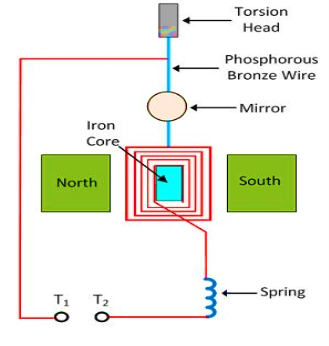
Figure 14: Ballistic-galvanometer
- When the charge passes through the galvanometer, their coil starts moving and gets an impulse.
- The impulse of the coil is proportional to the charges passes through it.
- The actual reading of the galvanometer achieves by using the coil having a high moment of inertia.
- The moment of inertia means the body oppose the angular movement.
- If the coil has a high moment of inertia, then their oscillations are large. Thus, accurate reading is obtained.
Theory of Ballistic Galvanometer
Consider the rectangular coil having N number of turns placed in a uniform magnetic field.
Let l be the length and b be the breadth of the coil.
The area of the coil is
A =lb …….. (1)
When the current passes through the coil, the torque acts on it. The magnitude of the torque is
 …….. (2)
Let the current flow through the coil for very short duration says dt and it is given by
 …….. (3)
If the current passing through the coil for t seconds,
 =
=  …….. (4)
The q be the total charge passes through the coil. The moment of inertia of the coil is given by I, and the angular velocity through ω. The angular momentum is
L = Iω …….. (5)
The angular momentum of the coil is equal to the force acting on the coil. Thus from equation (4) and (5), we get.
 …….. (6)
The Kinetic Energy (K) deflects the coil through an angle θ, and this deflection is restored through the spring.
Restoring torque = 
Kinetic energy = 
The resorting torque of the coil is equal to their deflection. Thus,

 …….. (7)
The periodic oscillation of the coil is given as


By multiplying the equation (7) from the above equation

 …….. (8)
On substituting the value of equation (6) in the equation (8) we get


Let 

The K is the constant of the ballistic galvanometer and is called the ballistic reduction factor.
Key Takeaways
- The galvanometer which is used for estimating the quantity of charge flow through it is called the ballistic galvanometer.
- It depends on the deflection of the coil which is directly proportional to the charge passes through it.
- The ballistic galvanometer consist coil of copper wire which is wound on the non-conducting frame of the galvanometer.
Let us consider a rectangular loop carrying a steady current I and placed in a uniform magnetic field experiences a torque. It does not experience a net force. This behaviour is analogous to that of electric dipole in a uniform electric field
We first consider the simple case when the rectangular loop is placed such that the uniform magnetic field B is in the plane of the loop. This is illustrated in Figure.
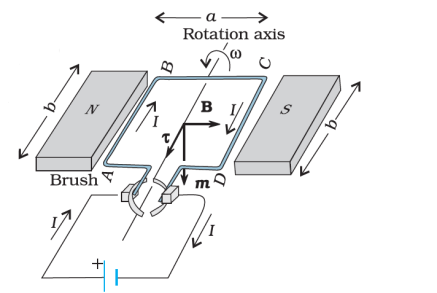
Figure 15: A rectangular current-carrying coil in uniform magnetic field
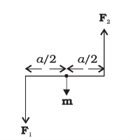
Figure 16: The couple acting on the coil.
The field exerts no force on the two arms AD and BC of the loop. It is perpendicular to the arm AB of the loop and exerts a force F1 on it which is directed into the plane of the loop. Its magnitude is,
F1 = I b B
Similarly, it exerts a force F2 on the arm CD and F2 is directed out of the plane of the paper.
F2 = I b B = F1
Thus, the net force on the loop is zero. There is a torque on the loop due to the pair of forces F1 and F2.
Figure shows a view of the loop from the AD end. It shows that the torque on the loop tends to rotate it anticlockwise. This torque is (in magnitude),


Where A = ab is the area of the rectangle.
We next consider the case when the plane of the loop, is not along the magnetic field, but makes an angle with it. We take the angle between the field and the normal to the coil to be angle θ. (The previous case corresponds to θ = π/2).
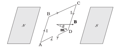
Figure 17: The area vector of the loop ABCD makes an arbitrary angle θ with the magnetic field
The forces on the arms BC and DA are equal, opposite, and act along the axis of the coil, which connects the centres of mass of BC and DA. Being collinear along the axis they cancel each other, resulting in no net force or torque. The forces on
Arms AB and CD are F1 and F2. They too are equal and opposite, with magnitude
F1 = F2 = IbB
But they are not collinear. This results in a couple as before. The torque is, however, less than the earlier case when plane of loop was along the magnetic field. This is because the perpendicular distance between the forces of the couple has decreased.
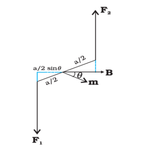
Figure 18: Top view of the loop. The forces F1 and F2 acting on the arms AB and CD are indicated.
Figure 18 is a view of the arrangement from the AD end and it illustrates these two forces constituting a couple. The magnitude of the torque on the loop is,
F1 sinθ + F2
  sinθ
sinθ
=IabB sinθ
= IAB sinθ
As θ 0, the perpendicular distance between the forces of the couple also approaches zero. This makes the forces collinear and the net force and
Torque zero.
The torques in equations can be expressed as vector product of the magnetic moment of the coil and the magnetic field. We define the magnetic moment of the current loop as,
m = I A
Where the direction of the area vector A is given by the right-hand thumb rule and is directed into the plane of the paper. Then as the angle between m and B is θ. Torque can be expressed by

The dimensions of the magnetic moment are [A][L2] and its unit is Am2.
We see that the torque t vanishes when m is either parallel or antiparallel to the magnetic field B. This indicates a state of equilibrium as there is no torque on the coil (this also applies to any object with a magnetic moment m).
When m and B are parallel the equilibrium is a stable one. Any small rotation of the coil produces a torque which brings it back to its original position. When they are antiparallel, the equilibrium is unstable as any rotation produces a torque which increases with the amount of rotation. The presence of this torque is also the reason why a small magnet or any magnetic dipole aligns itself with the external magnetic field.
If the loop has N closely wound turns, the expression for torque become
m = N I A
Key Takeaways
- Torque can be expressed by

- We see that the torque t vanishes when m is either parallel or antiparallel to the magnetic field B. This indicates a state of equilibrium as there is no torque on the coil.
- If the loop has N closely wound turns, the expression for torque become m = N I A
Numerical: A 100 turn closely wound circular coil of radius 10 cm carries a current of 3.2 A.
(a) What is the field at the centre of the coil?
(b) What is the magnetic moment of this coil? The coil is placed in a vertical plane and is free to rotate about a horizontal axis which coincides with its diameter. A uniform magnetic field of 2T in the horizontal direction exists such that initially the axis of the coil is in the direction of the field. The coil rotates through an angle of 90° under the influence of the magnetic field.
(c) What are the magnitudes of the torques on the coil in the initial and final position?
(d) What is the angular speed acquired by the coil when it has rotated by 90°? The moment of inertia of the coil is 0.1 kg m2.
Solution:
(a)
We know

Here, N = 100; I = 3.2 A, and R = 0.1 m. Hence,

(using π×3.2=10)

The direction is given by the right-hand thumb rule.
(b) The magnetic moment is given by
m = N I A = NIπr2 = 100 × 3.2 × 3.14 × 10–2 = 10 A m2
The direction is once again given by the right-hand thumb rule.
(c) = m× B = m B sinθ
Initially, θ= 0. Thus, initial torque i = 0.
Finally, θ = π/2 (or 90º).
Thus, final torque f = m B = 10 × 2 = 20 N m.
(d) From Newton’s second law
I = m B sinθ
Where I is the moment of inertia of the coil. From chain rule

Using this
I = m B sin dθ
Integrating from θ= 0 to θ = π/2


Current Sensitivity (Figure of merit): The figure of merit or current sensitivity of a moving coil galvanometer is the current required to produce a deflection of 1 mm on a scale kept at a distance of 1 m from the mirror. It is expressed in μA/mm. Current sensitivity is

The current sensitivity can be defined as the deflection produced by unit current on a scale kept at a distance 1m from the mirror of the galvanometer. Current sensitivity = θ/i
With this definition the figure of merit is the reciprocal of the current sensitivity.
Charge sensitivity: The charge sensitivity (the ballistic reduction factor) of a moving coil galvanometer is the charge (transient current) required to produce a deflection (throw or kick) of 1 mm on a scale kept at a distance of 1 m from the mirror. Charge sensitivity is

A moving coil galvanometer consists of a rectangular current carrying coil suspended in a uniform radial magnetic field. The current through the coil produces a torque which tries to rotate the coil. A restoring torque, provided by the stiffness of the suspension, is set up in the system and it counterbalances the electromagnetic torque.
Damping factors
1. Viscous drag of air and mechanical friction. The damping couple due to this is
Proportional to the angular velocity of the system. Usually it is very small and is
Neglected.
2. Induced currents in the neighbouring conductors. These currents produce two types of damping couple, the open circuit damping couple and the closed circuit damping couple.
The former one, according to the law of electromagnetic induction, is proportional to the angular velocity and is represented by -b  where, b is the damping coefficient. The latter one is directly proportional to the angular velocity and inversely proportional to the resistance of the circuit. It is given by
Where, involves all the coil constants such as area, magnetic flux and so on.
If C is the restoring couple per unit twist of the suspension and I is the moment of inertia of the oscillating system, the equation of motion is given by,


On substituting
 and
and 
Then

This equation is similar to the equation for a damped harmonic oscillator given by

Comparing these, we get
 and
and 
For damped oscillations, we have

Then

Where, C1 and C2 are undetermined constants to be evaluated from the initial conditions
Case 1: Non-oscillatory, aperiodic or dead beat motion
If the damping is high such that

The exponents of equation are real and the motion of the system is non-oscillatory. The angular displacement decays. This is the case of dead beat motion. The requirements of a dead beat galvanometer are,
- The moment of inertia I of the system must be small.
- The electromagnetic rotational resistance ‘b’ should be large and the suspension is not fine.
- The term , which involves all coil constants, should be large and the coil should be wound on a conducting frame.
- The resistance R must be small.
Case 2: Critical damping
When

The galvanometer is said to be critically damped. The motion of the coil is non-oscillatory and it comes to rest in a minimum time after deflection.
Case 3: Light damping: Ballistic motion
When

The exponents of the bracketed terms of equation are imaginary. Hence the motion of the coil is oscillatory in this case. The solution is given by


Where, 
The motion of the galvanometer is said to be ballistic when the damping factor

Is small. The requirements of a ballistic galvanometer are reverse of those for a dead beat galvanometer and are,
- The moment of inertia I of the system must be large.
- The electromagnetic rotational resistance ‘b’ is small and the suspension is fine.
- The term , which involves all coil constants, should be small and the coil should be wound on a non-conducting frame like wood or paper.
- The resistance R must be large.
Uses of ballistic galvanometers
- To compare capacities of capacitors.
- To compare e m f of cells.
- To find self and mutual inductance of coils.
- To find the magnetic flux or to find the intensity of a magnetic field.
- To find the angle of dip at a place using earth inductor.
- To find a high resistance, by method of leakage through a capacitor.
Key Takeaways
- A restoring torque, provided by the stiffness of the suspension, is set up in the system and it counterbalances the electromagnetic torque.
- One Damping factors is Viscous drag of air and mechanical friction. The damping couple due to this is proportional to the angular velocity of the system. Usually it is very small and is neglected.
- Second Damping factors is Induced currents in the neighbouring conductors. These currents produce two types of damping couple, the open circuit damping couple and the closed circuit damping couple.
Logarithmic damping
We have assumed that the whole kinetic energy imparted to the coil is completely used to twist the suspension wire. This is not exactly true. In
Actual practice the motion of the coil is damped by air resistance and induced current in the coil.
The first throw of the galvanometer is, therefore, smaller than it would have been in the absence of damping. So it is necessary to apply a correction for damping to the first throw of the galvanometer.

Figure 19: Logarithmic damping
Let θ1, θ2, θ3, …… be the successive maximum deflections from the zero position to the right and left as shown in the figure. Then it is found that,
 ……………. (1)
Where, d is a constant called the decrement per half vibration. Let d = eλ. Then, λ = loged. Here λ is called as the logarithmic decrement. Thus for a complete oscillation
 ……………. (2)
For one fourth of an oscillation the RHS of eqn.2 is eλ/2. Let θ be the true first throw in the absence of damping. The actual first throw in presence of damping is θ1, which is observed after the coil completes a quarter of vibration. Thus the decrement for θ is given by,
 ……………. (3)
Taking fourth root of eqn.2, we get,

 ……………. (4)
Or approximately,

 ……………. (5)
We calculate λ by observing the first 11 consecutive throws. Then


 ……………. (5)
Then damping is given by
 ……………. (6)
CDR
The resistance of a galvanometer at which the oscillation just stop is called critical damping resistance. For the case of Over damping or Dead beat, When


Where, the critical damping resistance

Key Takeaways
- In actual practice the motion of the coil is damped by air resistance and induced current in the coil.
- Then damping is given by

- The resistance of a galvanometer at which the oscillation just stop is called critical damping resistance.
References:
- Introduction to Electrodynamics – D.J. Griffiths (Pearson, 4th edition, 2015)
- Foundations of Electromagnetic Theory-Ritz and Milford (Pearson) 4th Edition
- Classical Electrodynamics, J. D. Jackson (Wiley), 1998
- Electricity and Magnetism D. C. Tayal (Himalaya Publishing house), 2014
- Electricity, Magnetism and Electromagnetic Theory- S. Mahajan and Choudhury ( Tata McGraw Hill)-2012