Unit - 4
Electrical Circuits & Network Theorems
4.1.1 AC Circuits
The voltage that changes its polarity and magnitude at regular interval of time is called an alternating voltage. Similarly, the direction of the current is changed and the magnitude of current changes with time it is called alternating current.
The circuit that is excited using alternating source is called an AC Circuit. The alternating current (AC) is used for domestic and industrial purposes. In an AC circuit, the value of the magnitude and the direction of current and voltages is not constant, it changes at a regular interval of time.
It travels as a sinusoidal wave completing one cycle as half positive and half negative cycle and is a function of time (t) or angle (θ=ωt).
In DC Circuit, the opposition to the flow of current is the only resistance of the circuit whereas the opposition to the flow of current in the AC circuit is because of resistance (R), Inductive Reactance (XL=2πfL) and capacitive reactance (XC = 1/2 πfC) of the circuit.
In AC Circuit, the current and voltages are represented by magnitude and direction. The alternating quantity may or may not be in phase with each other depending upon the various parameters of the circuit like resistance, inductance, and capacitance. The sinusoidal alternating quantities are voltage and current which varies according to the sine of angle θ.
For the generation of electric power, all over the world the sinusoidal voltage and current are selected because of the following reasons are given below.
- The sinusoidal voltage and current produce low iron and copper losses in the transformer and rotating electrical machines, which in turns improves the efficiency of the AC machines.
- They offer less interference to the nearby communication system.
- They produce fewer disturbances in the electrical circuit.
The usual waveform of an AC circuit is generally that of a sine wave, as these results in the most efficient transmission of energy. However in certain applications different waveforms are used, such as triangular or square waves
4.1.2 Representation of sinusoidal waveforms, peak, rms and average values (form factor and peak factor)
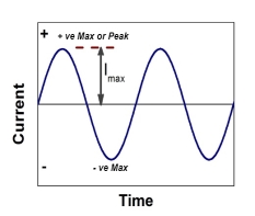
Figure 1: AC Current: Peak to peak value
Peak to peak value:
The value of an alternating quantity from its positive peak to negative peak
Amplitude = peak to peak values / 2
Average Value:
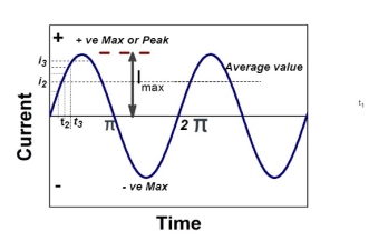
Figure 2: AC Current: Average Value
The arithmetic mean of all the value over complete one cycle is called as average value

 =
= 
For the derivation we are considering only hall cycle.
Thus  varies from 0 to ᴫ
i = Im Sin


Solving
We get

Similarly, Vavg=
The average value of sinusoid ally varying alternating current is 0.636 times maximum value of alternating current.
RMS value: Root mean square value
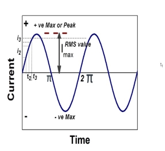
Figure 3: AC Current: RMS value
The RMS value of AC current is equal to the steady state DC current that required to produce the same amount of heat produced by ac current provided that resistance and time for which these currents flows are identical.

I rms = 
Direction for RMS value:
Instantaneous current equation is given by
i = Im Sin 
But 
I rms = 
= 
=
=
Solving
=
=
Similar we can derive
V rms=  or 0.707 Vm
 the RMS value of sinusoidally alternating current is 0.707 times the maximum value of alternating current.
Peak or krest factor (kp) (for numerical)
It is the ratio of maximum value to rms value of given alternating quantity
Kp = 
 Kp =
Kp = 
 Kp = 1.414
Form factor (Kf): For numerical It is the ratio of RMS value to average value of given alternating quality”.


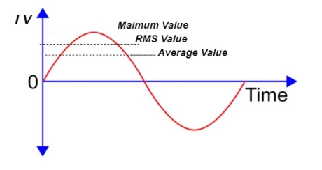
Figure 4: AC Current: Form factor
4.1.3 Kirchhoff’s Law
Kirchhoff’s Current Law (KCL) Statement
The algebraic sum of currents meeting at a junction or node in a electric circuit is zero ② or the summation of all incoming current is always equal to summation of all outgoing current in an electrical network.
Explanation
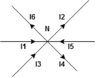
Figure 5: Kirchhoff’s Current Law (KCL)
Assuming the incoming current to be positive and outgoing current negative we have


Ie incoming current = ∑ outgoing current thus, the above Law can also be stated as the sum of current flowing towards any junction in an electric circuit is equal to the sum of currents flowing away from that junction
Kirchhoff’s Voltage Law (KVL)
Statement: The algebraic summation of all Voltage in any closed circuit or mesh of loop zero.
Ie ∑ Voltage in closed loop = 0 the summation of the Voltage rise (voltage sources) is equal to summation of the voltage drops around a closed loop in 0 circuit for explanation from here
Determination of sigh and direction of currents (Don’t write in exams just for understanding)

Figure 6: Sign convention
Current entering a resistor is +ve and leaving should be –ve
Now
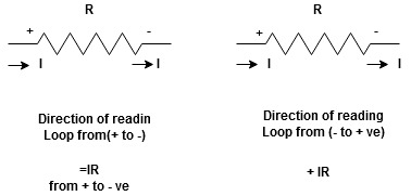


Figure 7: Sign convention
Potential Rise Potential Drop
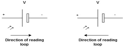
Figure 8: Sign convention
We are reading from +V to –V we are reading from –V to +V
 potential drops
  potential rise
 -V
-V  +V
+V
Given Circuit
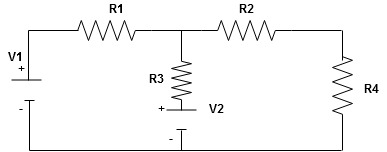
Figure 9: Circuit
First identify no of loops and assign direction of current flowing in loop
Note: no of loops in circuit = No of unknown currents = no, of equations in the circuit
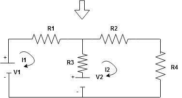
Figure 10: Circuit
Note: keep loop direction and current direction same ie either clockwise or anticlockwise for all loops I1 I2
Now according to direction of direction assign signs (+ve to –ve) to the resistors
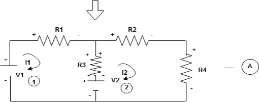
Figure 11: Circuit
Note: voltage sources (V) polarities does not change is constant.
Note: for common resistor between 2 loops appearing in the circuit like R3 give signs according to separate loops as shown
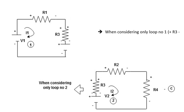
Figure 12: KVL
Now consider diagram A and write equations
Two loops  two unknown currents
  two equation
Apply KVL for loop ① [B. Diagram]
(+ to drop -) = - sign and (- to rise +) = + sign
 for drop = -sign
 for rise = + sign
-
-( ) R2 is considered because in R3,2 currents are flowing
  and
and  and we have taken (
 ) because we are considering loop no 1 and current flowing is
  in loop no 1
 )
)
Similarly for loop no. 2 currents flowing is  resistor R3 it should be
  )R3
)R3
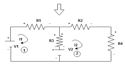
Figure 13: KVL
Consider loop no. 1 apply KVL
- …….①
…….①
-
Consider loop no. 2 apply KVL
- …….②
…….②
-
After solving equation ① and ② we will get branch current  and
and 
4.1.4 Complex Reactance and Impedance
Study of AC circuits containing pure R, Pure C and L, phasor diagram and waveform
3 Basic element of AC circuit.
1] Resistance
2] Inductance
3] Capacitance
Each element produces opposition to the flow of AC supply in forward manner.
Reactance
- Inductive Reactance (XL)
It is opposition to the flow of an AC current offered by inductor.
XL = ω L But ω = 2 ᴫ F
 XL = 2 ᴫ F L
It is measured in ohm
 XL∝ FInductor blocks AC supply and passes dc supply zero
2. Capacitive Reactance (Xc)
It is opposition to the flow of ac current offered by capacitor
Xc = 
Measured in ohm
 Capacitor offers infinite opposition to dc supply
Impedance (Z)
The ac circuit is to always pure R pure L and pure C it well attains the combination of these elements. “The combination of R1 XL and XC is defined and called as impedance represented as
Z = R +i X
Ø = 0
 only magnitude
R = Resistance, i = denoted complex variable, X =Reactance XL or Xc
Polar Form
Z =  L I
L I
Where  =
=
 Measured in ohm
Power factor (P.F.)
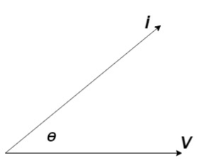
Figure 14: Power factor (P.F.)
It is the cosine of angle between voltage and current

If Ɵis –ve or lagging (I lags V) then lagging P.F.
If Ɵ is +ve or leading (I leads V) then leading P.F.
If Ɵ is 0 or in phase (I and V in phase) then unity P.F.
Ac circuit containing pure resisting
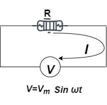
Figure 15: Ac circuit containing pure resisting
Consider Circuit Consisting pure resistance connected across ac voltage source
V = Vm Sin ωt ①
According to ohm’s law i =  =
= 
But Im = 
 ②
②
Phases diagram
From ① and ② phase or represents RMD value.
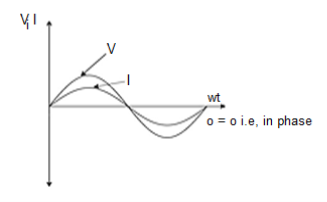
Figure 16: Waveform
Power P = V. i
Equation P = Vm sin ω t Im sin ω t
P = Vm Im Sin2 ω t


Average power
Pavg = 
Pavg = 
Pavg = Vrms Irms
Power form [Resultant]
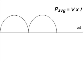
Figure 17: Power form
Ac circuit containing pure Inductors
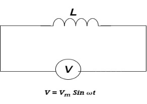
Figure 18: Ac circuit containing pure Inductors
Consider pure Inductor (L) is connected across alternating voltage. Source
V = Vm Sin ωt
When an alternating current flow through inductance it set ups alternating magnetic flux around the inductor.
This changing the flux links the coil and self-induced emf is produced
According to faradays Law of E M I
e = 
At all instant applied voltage V is equal and opposite to self-induced emf [ lenz’s law]
V = -e
 =
= 
But V = Vm Sin ωt

 dt
dt
Taking integrating on both sides
 dt
dt
 dt
dt

 (-cos
(-cos  )
)

But sin (– ) = sin (+
 )
)
 sin (
sin ( -
-  /2)
/2)
And Im= 
 /2)
/2)
 /2
/2
= -ve
= lagging
= I lag v by 900
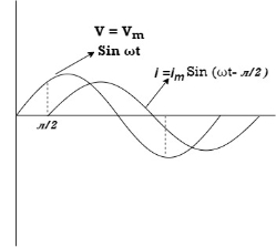
Figure 19: Phasor
Phasor:
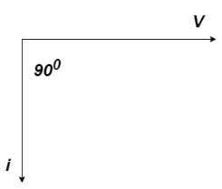
Figure 20: Phasor
Power P = Ѵ. I
= Vm sin wt Im sin (wt  /2)
/2)
= Vm Im Sin wt Sin (wt –  /s)
/s)
 ①
①
And
Sin (wt -  /s) = - cos wt ②
Sin (wt –  ) = - cos
 sin 2 wt from ① and ②
The average value of sin curve over a complete cycle is always zero

 Pavg = 0
Ac circuit containing pure capacitors:
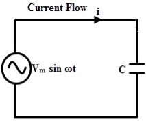
Figure 21: Ac circuit containing pure capacitors
Consider pure capacitor C is connected across alternating voltage source
Ѵ = Ѵm Sin wt
Current is passing through capacitor the instantaneous charge ɡ produced on the plate of capacitor
ɡ = C Ѵ
ɡ = c Vm sin wt
The current is rate of flow of charge
i= (cvm sin wt)
i = c Vm w cos wt
Then rearranging the above eqth.
i =  cos wt

 = sin (wt +
  X/2)
X/2)
i =  sin (wt + X/2)
But 
 X/2)
X/2)

= leading
= I leads V by 900
Waveform:
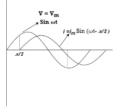
Figure 22: Phasor
Phase
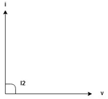
Figure 23: Phasor
Power P= Ѵ. i
= [Vm sinwt] [ Im sin (wt + X/2)]
= Vm Im Sin wt Sin (wt + X/2)]
 (cos wt)


 to charging power waveform [resultant].
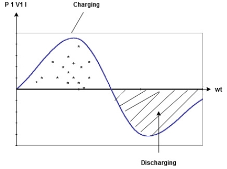
Figure 24: Charging and discharging
4.1.5 Study of reactance and impedance
Impedance (Z)
The ac circuit is to always pure R pure L and pure C it well attains the combination of these elements. “The combination of R1 XL and XC is defined and called as impedance represented as
Z = R +i X
Ø = 0
 only magnitude
R = Resistance, i = denoted complex variable, X =Reactance XL or Xc
Polar Form
Z =  L I
L I
Where  =
=
 Measured in ohm
Admittance:
The reciprocal of impedance is admittance. Its unit is mho (siemens)
Y=  =
= 
V=IZ
I=VY
Y=  =
= 
Y= G+iB
G= 
B= 
Key Takeaways
- The voltage that changes its polarity and magnitude at regular interval of time is called an alternating voltage.
- Similarly, the direction of the current is changed and the magnitude of current changes with time it is called alternating current.
- The circuit that is excited using alternating source is called an AC Circuit.
- Kirchhoff’s Current Law (KCL) State that The algebraic sum of currents meeting at a junction or node in a electric circuit is zero ② or the summation of all incoming current is always equal to summation of all outgoing current in an electrical network.
- Kirchhoff’s Voltage Law (KVL) state that the algebraic summation of all Voltage in any closed circuit or mesh of loop zero.
R-L-C series circuit
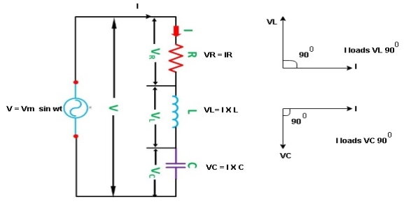
Figure 25: R-L-C series circuit
Consider ac voltage source V = Vm sin wt connected across combination of R L and C. When I flowing in the circuit voltage drops across each component as shown below.
VR = IR, VL = I  L, VC = I
  C
C
- According to the values of Inductive and Capacitive Reactance I e XL and XC decides the behaviour of R-L-C series circuit according to following conditions
① XL> XC, ② XC> XL, ③ XL = XC
① XL > XC: Since we have assumed XL> XC
 Voltage drop across XL> than XC
 VL> VC A
- Voltage triangle considering condition A
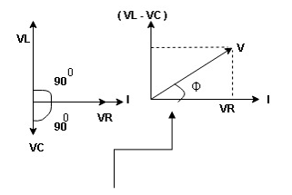
Figure 26: R-L-C series circuit
VL and VC are 180 0 out of phase.
Therefore cancel out each other
 Resultant voltage triangle
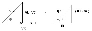
Figure 27: R-L-C series circuit
Now V = VR + VL + VC c phasor sum and VL and VC are directly in phase opposition and VL
 VC
VC their resultant is (VL - VC).
From voltage triangle
V = 
 V =
V = 
 V = I
V = I 

Impendence  : divide voltage
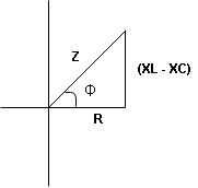
Figure 28: R-L-C series circuit: Impendence
Rectangular form Z = R + j (XL – XC)
Polar form Z =  l + Ø B
Where  =
= 
And Ø = tan-1 
Voltage equation: V = Vm Sin wt
Current equation
i =  from B
i =  L-Ø C
L-Ø C
As VL VC the circuit is mostly inductive and
  I lags behind V by angle Ø
 Since i =
  L-Ø
L-Ø
 i = Im Sin (wt – Ø) from c
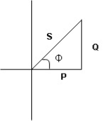
Figure 29: R-L-C series circuit
XC  XL: Since we have assured XC
  XL
XL
 the voltage drops across XC
  than XL
 XC
XC  XL (A)
 voltage triangle considering condition (A)
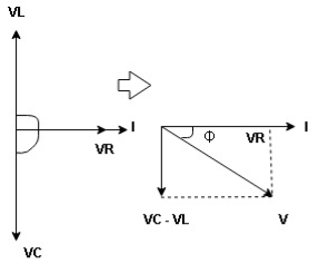
Figure 30: R-L-C series circuit
 Resultant Voltage
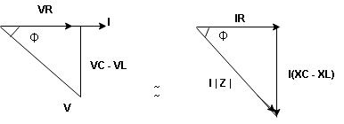
Figure 31: R-L-C series circuit
Now V = VR + VL + VC  phases sum and VL and VC are directly in phase opposition and VC
 VL
VL  their resultant is (VC – VL)
From voltage 
V = 
V = 
 V =
V = 
 V =
V = 

 Impedance
  : Divide voltage
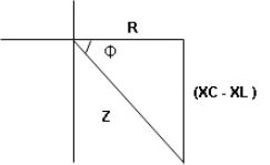
Figure 32: R-L-C series circuit
- Rectangular form: Z + R – j (XC – XL) – 4th quadrant
- Polar form: Z =
 L -
L -
Where 
And Ø = tan-1 – 
- Voltage equation: V = Vm Sin wt
- Current equation: i =
 from B
 - i =
 L+Ø C
L+Ø C
As VC  the circuit is mostly capacitive and
  leads voltage by angle Ø
Since i =  L + Ø
L + Ø
 Sin (wt – Ø) from C
- Power
 :
:
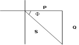
Figure 33: R-L-C series circuit
- XL= XC (resonance condition):
ɡȴ XL= XC then VL= VC and they are 1800 out of phase with each other  they will cancel out each other and their resultant will have zero value.
Hence resultant V = VR and it will be in phase with I as shown in below phasor diagram.
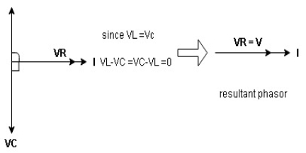
Figure 34: R-L-C series circuit
From above resultant phasor diagram
V =VR + IR
Or V = I  lZl
lZl
Because lZl + R
Thus Impedance Z is purely resistive for XL = XC and circuit current will be in phase with source voltage.
Since VR= V Ø is zero when XL = XC  power is unity
Ie pang = Vrms I rms cos Ø = 1 cos o = 1
Maximum power will be transferred by condition. XL = XC
Series and parallel resonance
Definition: it is defined as the phenomenon which takes place in the series or parallel R-L-C circuit which leads to unity power factor
Voltage and current in R – L - C ckt. Are in phase with each other
Resonance is used in many communicate circuit such as radio receiver.
Resonance in series RLC series resonance in parallel RLC anti resonance / parallel resonance.
- Condition for resonance XL = XC
- Resonant frequency (Fr): for given values of R-L-C the inductive reactance XL become exactly aqual to the capacitive reactance Xc only at one particular frequency. This frequency is called as resonant frequency and denoted by (fr)
- Expression for resonant frequency(fr): we know thet XL = 2ƛ FL - Inductive reactance
Xc =  - capacitive reactance
At a particular frequency ȴ = fr, the Inductive and capacitive reactance are exactly equal
 XL = XC ……at ȴ = fr
i.e  L =
L = 
 fr2 =
fr2 = 
 fr =
fr =  H2
H2
And  = wr =
  rad/sec
Quality factor / Q factor
The quality of resonance circuit is measured in terms of efficiency of L and C to stare energy and the efficiency of L and C to store energy as measured in terms of a factor called quality factor or Q factor it is expressed as
Q =  and Q =
The sharpness of tuning of R-L-C series circuit or its selectivity is measured by value of Q. As the value of Q increases, sharpness of the curve also increases and the selectivity increases.
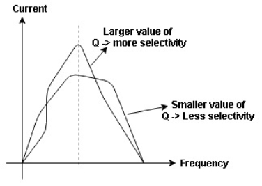
Figure 35: Quality factor / Q factor
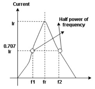
Figure 36: Bandwidth (BW)
Bandwidth (BW) = f2 = b1
 and
and  are the frequency at which the power delivered to the resistor is reduced to 50% of the power delivered to it at resonance
  these frequency are called as half power frequency
Bw = fr/Q
Resonance in Parallel circuit:
When a coil is in parallel with a capacitor, as shown below. The circuit is said to be in resonance.
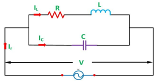
Figure 37: Resonance in Parallel circuit
The resonant frequency for above circuit is fr =  Hz
Hz
The current at resonance is I=
The value L/RC is known as dynamic impedance.
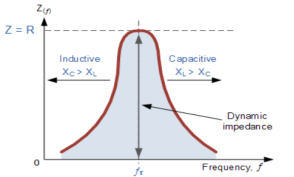
Figure 38: Resonance in Parallel circuit
The current at resonance is minimum. The circuits admittance must be at its minimum and one of the characteristics of a parallel resonance circuit is that admittance is very low limiting the circuits current. Unlike the series resonance circuit, the resistor in a parallel resonance circuit has a damping effect on the circuit bandwidth making the circuit less selective.
Also, since the circuit current is constant for any value of impedance, Z, the voltage across a parallel resonance circuit will have the same shape as the total impedance and for a parallel circuit the voltage waveform is generally taken from across the capacitor.
Bandwidth and selectivity:
 and
and  are the frequency at which the power delivered to the resistor is reduced to 50% of the power delivered to it at resonance
  these frequency are called as half power frequency
Bw = fr/Q
Q =  =
=  fCR = R
Resonant Frequency:
The resonant frequency for parallel resonant circuit is given as
fR= 
Where L= inductance of the coil
C = is the capacitance
Rs = Resistive value of coil.
Key Takeaways
- Voltage equation : V = Vm Sin wt
- Current equation
 i = Im Sin (wt – Ø)

- The quality of resonance circuit is measured in terms of efficiency of L and C to stare energy and the efficiency of L and C to store energy as measured in terms of a factor called quality factor or Q factor
1. Numerical: A coil takes a current of 6A when connected to 24V dc supply. To obtain the same current with 50HZ ac, the voltage required was 30V. Calculate inductance and p.f of coil?
Sol: The coil will offer only resistance to dc voltage and impedance to ac voltage
R =24/6 = 4ohm
Z= 30/6 = 5ohm
XL = 
= 3ohm
Cosφ =  = 4/5 = 0.8 lagging
2. Numerical: The potential difference measured across a coil is 4.5V, when it carries a dc current of 8A. The same coil when carries ac current of 8A at 25Hz, the potential difference is 24V. Find current and power when supplied by 50V,50Hz supply?
Sol: R=V/I= 4.5/8 = 0.56ohm
At 25Hz, Z= V/I=24/8 =3ohms
XL = 
= 2.93ohm
XL = 2 fL = 2
 x 25x L = 2.93
L=0.0187ohm
At 50Hz
XL = 2x3 =6ohm
Z =  = 5.97ohm
I= 50/5.97 = 8.37A
Power = I2R = 39.28W
3. Numerical: A coil having inductance of 50mH an resistance 10ohmis connected in series with a 25 F capacitor across a 200V ac supply. Calculate resonant frequency and current flowing at resonance?
Sol: f0= = 142.3Hz
I0 = V/R = 200/10 = 20A
4. Numerical: A 15mH inductor is in series with a parallel combination of 80ohm resistor and 20 F capacitor. If the angular frequency of the applied voltage is 1000rad/s find admittance?
Sol: XL = 2 fL = 1000x15x10-3 = 15ohm
XL = 1/ C = 50ohm
Impedance of parallel combination Z = 80||-j50 = 22.5-j36
Total impedance = j15+22.5-j36 = 22.5-j21
Admittance Y= 1/Z = 0.023-j0.022 siemens
5. Numerical: A circuit connected to a 100V, 50 Hz supply takes 0.8A at a p.f of 0.3 lagging. Calculate the resistance and inductance of the circuit when connected in series and parallel?
Sol: For series Z =100/0.8 = 125ohm
Cos φ = 
R = 0.3 x 125 = 37.5ohm
XL =  = 119.2ohm
XL = 2 fL = 2
 x 50x L
119.2 = 2 x 50x L
L= 0.38H
For parallel:
Active component of current = 0.8 cosφ = 0.3x0.3 = 0.24A
R = 100/0.24 =416.7ohm
Quadrature component of current = 0.8 sinφ = 0.763
XL= 100/0.763 = 131.06ohm
L= 100/0.763x2 x50 = 0.417H
Ideal and practical Voltage and Current source:
A voltage source is a device which provides a constant voltage to load at any instance of time and is independent of the current drawn from it. This type of source is known as an ideal voltage source. Practically, the ideal voltage source cannot be made. It has zero internal resistance. It is denoted by this symbol.
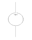
Figure 39: Voltage source symbol
Ideal Voltage Source
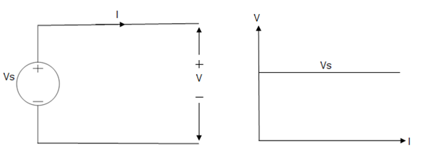
Figure 40: Ideal Voltage Source
The graph represents the change in voltage of the voltage source with respect to time. It is constant at any instance of time.
Voltage sources that have some amount of internal resistance are known as a practical voltage source. Due to this internal resistance, voltage drop takes place. If the internal resistance is high, less voltage will be provided to load and if the internal resistance is less, the voltage source will be closer to an ideal voltage source. A practical voltage source is thus denoted by a resistance in series which represents the internal resistance of source.
Practical Voltage source
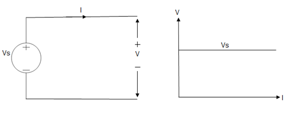
Figure 41: Practical Voltage source
The graph represents the voltage of the voltage source with respect to time. It is not constant but it keeps on decreasing as the time passes.
Current source
A current source is a device which provides the constant current to load at any time and is independent of the voltage supplied to the circuit. This type of current is known as an ideal current source; practically ideal current source is also not available. It has infinite resistance. It is denoted by this symbol.
Ideal Current source
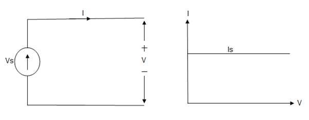
Figure 42: Ideal Current source
The graph represents the change in current of the current source with respect to time. It is constant at any instance of time.
Why ideal Current source has infinite resistance?
A current source is used to power a load, so that load will turn on. We try to supply 100% of the power to load. For that, we connect some resistance to transfer 100% of power to load because the current always takes the path of least resistance. So, in order for current to go to the path of least resistance, we must connect resistance higher than load. This is why we have the ideal current source to have infinite internal resistance. This infinite resistance will not affect voltage sources in the circuit.
Practical Current source
Practically current sources do not have infinite resistance across there but they have a finite internal resistance. So the current delivered by the practical current source is not constant and it is also dependent somewhat on the voltage across it.
A practical current source is represented as an ideal current source connected with resistance in parallel.
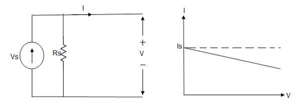
Figure 43; Practical Current source
The graph represents the current of the current source with respect to time. It is not constant but it also keeps on decreasing as the time passes.
Examples of current and voltage sources
The examples of current source are solar cells, transistors and examples of some voltage sources are batteries and alternators.
This was all about ideal and practical sources of power. The ideal sources are very useful for calculations in theory but as ideal sources are not practically possible, only practical sources are used in practical circuits. The batteries we use are a practical source of power and the voltage and current decreases as we use it. Thus both are useful to us in their own ways.
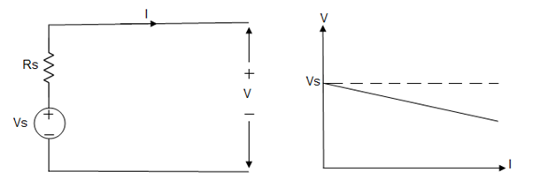
Figure 44: Examples of current and voltage sources
Key Takeaways
- A voltage source is a device which provides a constant voltage to load at any instance of time and is independent of the current drawn from it. This type of source is known as an ideal voltage source.
- Practically, the ideal voltage source cannot be made. It has zero internal resistance.
- The examples of current source are solar cells, transistors and examples of some voltage sources are batteries and alternators.
4.4.1 Thevenin’s Theorem
Thevenin’s Theorem states that “Any linear circuit containing several voltages and resistances can be replaced by just one single voltage in series with a single resistance connected across the load”.
For the circuit as shown in figure find the current through RL = R2 = 1Ω resistor (Ia-b) branch using Thevenin’s theorem. Find the voltage across the current source.
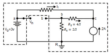
Figure 45: Thevenin’s Theorem
Step 1: Disconnect the load resistance and reconnect the circuit.
Step 2: Apply any method to calculate Vth
At node C
2 + I1 + I2 =0
2 + (3 -Vc)/3 + (0-Vc/6) -- Vc = 6V
The currents I1 and I2 are computed by the following expressions:
I1 = Va -Vc/3 = 3-6/3 = -1A (I1 is flowing from c to a)
I2 = 0 – Vc/6 = -6/6 = -1A (I2 is flowing from c to a)
Step-3:
Redraw the circuit indicating the direction of currents in different branches. One can find the Thevenin’s voltage VTh using KVL around the closed path ‘gabg’
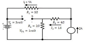
Figure 46: Thevenin’s Theorem
VTh = Vag − Vbg = 3 − 2 =1volt
Step 4:
Replace all sources by their internal resistances. In this problem, voltage source has an internal resistance zero (0) (ideal voltage source) and it is short-circuited with a wire.
On the other hand, the current source has an infinite internal resistance (ideal current source) and it is open-circuited (just remove the current source).
Thevenin’s resistance RTh of the fixed part of the circuit can be computed by looking at the load terminals ‘a’- ‘b’
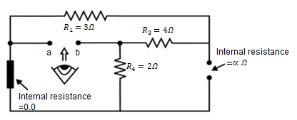
Figure 47: Thevenin’s Theorem
RTh = ( R1 + R3 ) & R4 = ( 3 + 4 )&2 = 1.555Ω
Step-5: Place RTh in series with VTh to form the Thevenin’s equivalent circuit. Reconnect the original load resistance RL = R2 = 1 Ω to the Thevenin’s equivalent circuit.
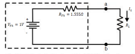
Figure 48: Thevenin’s Theorem

Step-6: The circuit is redrawn to indicate different branch currents. Referring to one can calculate the voltage Vbg and voltage across the current source (Vcg ) using the following equations.
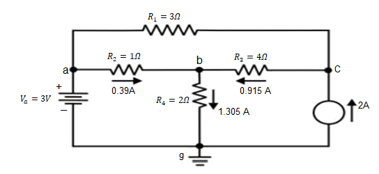
Figure 49: Thevenin’s Theorem
Vbg = Vag − Vab = 3 − 1 × 0.39 =2.61 volt.
Ibg = 2.61 2 = 1.305 A;
Icb = 1.305 − 0.39 = 0.915 A
Vcg = 4 × 0.915 + 2 ×1.305 =6.27 volt.
Numerical: For the circuit shown in figure, find the current IL through 6 Ω resistor using Thevenin’s theorem.
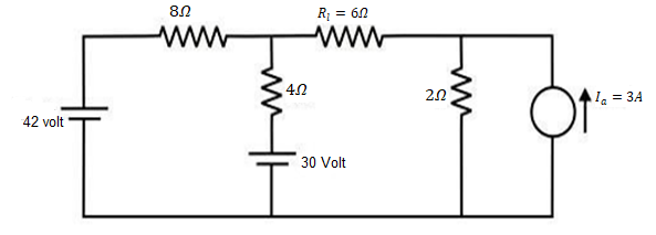
Figure 50: Thevenin’s Theorem: Circuit
Step-1:
Disconnect 6 Ω from the terminals ‘a’ and ‘b’ and the corresponding circuit diagram. Consider point ‘g’ as ground potential and other voltages are measured with respect to this point.
Step-2:
Apply any suitable method to find the Thevenin’s voltage (VTh )
KVL is applied around the closed path ‘gcag’ to compute Thevenin’s voltage.
42 – 8I – 4I -30 = 0 ; I = 1A
Vag = 30+4 = 34 volt
Vbg = 2 x 3 = 6 volt
Vth = Vab = Vag – Vbg = 34 -6 = 28 volt
Step-3:
Thevenin’s resistance RTh can be found by replacing all sources by their internal resistances all voltage sources are short-circuited and current sources are just removed or open circuited.
Rth = (8 x4) / 12 + 2 = 14/3 = 4.666Ω
Step-4:
Thevenin’s equivalent circuit is now equivalently represents the original circuit
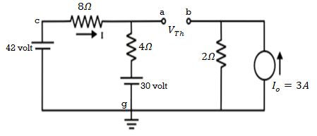
Figure 51: Thevenin’s Theorem: Circuit
IL = Vth / Rth + RL = 28 / 4.666 +6 = 2.625 A
4.4.2 Norton’s Theorem
Norton’s Theorem states that “Any linear circuit containing several energy sources and resistances can be replaced by a single Constant Current generator in parallel with a Single Resistor”.
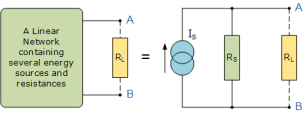
Problem:
Find RN, IN, the current flowing through and load Voltage across the load resistor in fig (1) by using Norton’s Theorem.

Figure 52: Norton’s Theorem: Circuit
Step 1:
Short the 1.5 Ω load resistor.
Step 2:
Norton current.
Short AB terminals to obtain IN . The total resistance of the circuit is
2Ω + (6Ω || 3Ω)
RT = 4 Ω
IT = V / RT = 12/ 4 = 3 A
IN = 3 A x [ 6Ω / 3 + 6 )] = 2A
IN = 2A
Step 3:
Open current sources, Short Voltage sources and Open Load resistor.
Step 4:
Calculate Norton Resistance (RN)
Reduce 12V dc source. 3Ω resistor is in series with combination of 6Ω and 2Ω resistor
3Ω + (6Ω||2Ω)
3Ω + 1.5 Ω = 4.5 Ω; RN = 4.5 Ω
Step 5:
Connect RN in parallel with current source IN and the load resistor.
Step 6:
The load current through Load resistor
IL = IN x [ RN /(RN + RL)
=2 A x ( 4.5 / 4.5 + 1.5 K) = 1.5 A
IL = 1.5 A
The voltage across load resistor
VL = IL x RL
= 1.5 x 1.5
VL = 2.25 V
4.4.3 Superposition Theorem
Superposition theorem states that in any linear, active, bilateral network having more than one source, the response across any element is the sum of the responses obtained from each source considered separately and all other sources are replaced by their internal resistance. The superposition theorem is used to solve the network where two or more sources are present and connected.
If a number of voltage or current sources are acting in a linear network, the resulting current in any branch is the algebraic sum of all the currents that would be produced in it when each source acts alone while all the other independent sources are replaced by their internal resistances.
Using Superposition theorem determine the voltage drop and current across the resistor 3.3K as shown in figure below
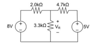
Figure 53: Superposition theorem Circuit
Step 1:
Remove 8V power supply from the original circuit such that the new circuit becomes as the following and measure the voltage across resistor.
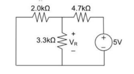
Figure 54: Superposition theorem Circuit
Here 3.3 K and 2K are in parallel therefore the resultant resistance will be 1.245K
Using voltage divider rule across 1.245K will be
V1 =[1.245/(1.245+4.7)] * 5 = 1.047V
Step 2:
Remove the 5V power supply from the original circuit such that the new circuit becomes the following and then measure the voltage across resistor.
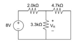
Here 3.3K and 4.7K are in parallel therefore the resultant resistance will be 1.938K. Using voltage divider rule voltage across 1.938K will be
V2 =[1.938(1.938+2)] *8 = 3.9377V
Therefore, voltage drop across 3.3K resistor is V1+V2 = 1.047 + 3.9377 = 4.9847V
4.4.4 Reciprocity Theorem
Reciprocity Theorem states that, the value of current due to a single source in any particular branch of circuit is equal to the value of current in the original branch where the source was placed when the source is shifted to that particular branch of circuit. This theorem is only applicable for a reciprocal network i.e. linear and bilateral circuit having only one independent source. This theorem can, however, be used for both AC and DC circuit.
In simple words, we can state the reciprocity theorem as when the places of voltage and current source in any network are interchanged the amount or magnitude of current and voltage flowing in the circuit remains the same.
The location of the voltage source and the current source may be interchanged without a change in current. However, the polarity of the voltage source should be identical with the direction of the branch current in each position.
The Reciprocity Theorem is explained with the help of the circuit diagram shown below
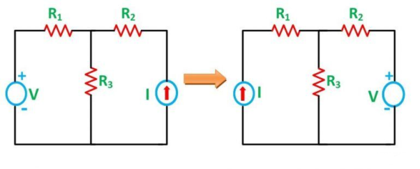
Figure 55: Circuit diagram
The various resistances R1, R2, R3 is connected in the circuit diagram above with a voltage source (V) and a current source (I). It is clear from the figure above that the voltage source and current sources are interchanged for solving the network with the help of Reciprocity Theorem.
The limitation of this theorem is that it is applicable only to single-source networks and not in the multi-source network. The network where reciprocity theorem is applied should be linear and consist of resistors, inductors, capacitors and coupled circuits. The circuit should not have any time-varying elements.
Steps for Solving a Network Utilizing Reciprocity Theorem
- Firstly, select the branches between which reciprocity has to be established.
- The current in the branch is obtained using any conventional network analysis method.
- The voltage source is interchanged between the branch which is selected.
- The current in the branch where the voltage source was existing earlier is calculated.
- Now, it is seen that the current obtained in the previous connection, i.e., in step 2 and the current which is calculated when the source is interchanged, i.e., in step 4 are identical to each other.
Example
Let us consider the circuit below.
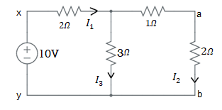
Figure 56: Circuit diagram
Let us first check if we can apply the theorem of not. Since, the circuit is a linear bilateral network and hence reciprocal. Therefore, we can apply reciprocity theorem in this circuit.
Let us assume that we want to check the validity of reciprocity theorem in branch x-y and a-b. For this, first we find the current though the branch a-b as below.
= (3×3)/6 + 2
= 3.5 Ω
Therefore, current I1
= 10/3.5 A
= 2.86 A
Now the current through branch a-b may be calculated using current division rule as shown below.
I2 = (3x I1)/(3+3)S
= 2.86/2
=1.43 A
Let us now change the position of voltage source and put it into branch a-b. This shown in figure below.
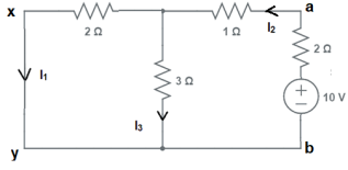
Figure 57: Circuit diagram
Our aim is to find the value of current in branch x-y i.e. the branch where the source was originally placed when it is shifted to the particular branch a-b where we calculated the current.
Let us first find the equivalent resistance across terminals a-b first. This resistance is calculated as below.
Equivalent resistance across terminals x-y
= 2+1+6/5
= 4.2 Ω
Current I2 = 10/4.2
= 2.38 A
Using current division rule, the current in branch x-y may be find as shown below.
I1 = (2.38×3)/5
= 1.43 A
Carefully notice the value of currents I1 and I2. They are same.
Thus, Reciprocity Theorem can be understood in another way. In electrical, cause is voltage and effect is current. This simply means, voltage causes current to flow. Let us call voltage as excitation and current as response. It is clear from the above workout that, interchanging the position of excitation and response does not alter the value of response.
Reciprocity theorem may be stated as: the ratio of excitation and response remains constant even if we interchange the position of excitation and response in a reciprocal network.
4.4.5 Maximum Power Transfer Theorem
Maximum power transfer theorem states that AC voltage source will deliver maximum power to the variable complex load only when the load impedance is equal to the complex conjugate of source impedance.
Proof:
Replace any two terminal linear network or circuit to the left side of variable load resistor having resistance of RL ohms with a Thevenin’s equivalent circuit. We know that Thevenin’s equivalent circuit resembles a practical voltage source.
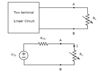
Figure 58: Maximum power transfer theorem
The amount of power dissipated across the load resistor is
PL = I 2 R L ----------------------(1)
Substitute I = Vth / Rth + RL
PL = Vth / (Rth + RL ) 2 RL
PL = Vth 2 { RL / (RTH + RL) 2 ------------------------------(2)
Condition for Maximum Power Transfer
For maximum or minimum, first derivative will be zero. So, differentiate Equation 1 with respect to RL and make it equal to zero.
DPL / d RL = V Th 2 { (Rth + RL) 2 x 1 -RL x 2(Rth + RL) / (Rth + RL) 4 } =0
(Rth + RL) 2 – 2RL (Rth + RL) = 0
(Rth + RL) (Rth + RL – 2 RL) = 0
Rth - RL = 0
Rth = RL or RL = Rth
Therefore, the condition for maximum power dissipation across the load is RL=RTh. That means, if the value of load resistance is equal to the value of source resistance that is Thevenin’s resistance, then the power dissipated across the load will be of maximum value.
Substitute RL = Rth and PL = PL,max
PL,max = V th 2 { Rth / (Rth + Rth ) 2 }
= V th 2 ( Rth / 4 Rth 2 )
= V th 2 / 4 Rth
PL,max = V th 2 / 4 RL [RL = Rth]
Efficiency of Maximum power transfer
 = PL,max/ Ps
PL,max = maximum amount of power transferred to the load
Ps = amount of power generated by the source.
The amount of power generated by the source is
Ps = I2 Rth + I2 RL
Ps = 2 I2 Rth ; since RL = Rth
Substitute I = Vth / 2 Rth
Ps = 2(Vth / 2Rth) 2 Rth
Ps = 2(Vth / 4Rth) 2 Rth
Ps = Vth 2 / 2 Rth
Substituting with PL max and Ps
= (Vth 2 / 4 Rth) / (Vth 2 / 2 Rth)
 = ½
= ½
Problem:
Find the maximum power that can be delivered to the load resistor RL of the circuit shown in the following figure.

Figure 59: Circuit diagram
Step 1 – Using Thevenin’s circuit we get
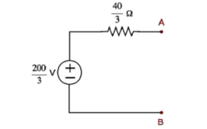
Figure 60: Circuit diagram
Thevenin’s voltage Vth = 200/3 and Thevenin’s resistance Rth = 40/3
Step 2 – Replace the left side of terminals A & B of the given circuit with the above Thevenin’s equivalent circuit. The resultant circuit diagram will be
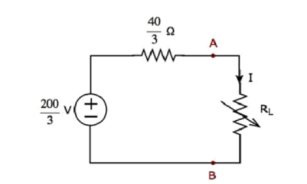
Figure 61: Circuit diagram
Step 3 − We can find the maximum power that will be delivered to the load resistor, RL by using the following formula.
P L,max = Vth 2 / 4 Rth
Substitute VTh=200/3 and RTh=40/3Ω
P L,max = (200/3) 2 / 4 (40/3)
Therefore, the maximum power that will be delivered to the load resistor RL of the given circuit is 250/3.
Problem:
For the circuit shown find the value of RL that absorbs maximum power from the circuit and the corresponding power under this condition.
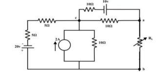
Figure 62: Circuit diagram
Load resistance RL is disconnected from the terminals ‘a’ and ‘b’ and the corresponding circuit diagram.
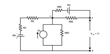
Figure 63: Circuit diagram
The above circuit is equivalently represented by a Thevenin circuit and the corresponding Thevenin voltage VTh and Thevenin resistance RTh are calculated by following the steps given below:
Considering 20V only
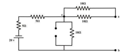
Figure 64: Circuit diagram
From the above circuit the current through ‘b-c’ branch =20/ 20 = 1𝐴 (𝑓𝑟𝑜𝑚 𝑎 𝑡𝑜 𝑏). Whereas the voltage across the ‘b-a’ branch vba =1 ×10 =10 volt . Since ’b’ is higher potential than ‘a’ ∴vab = − 10volt.
Considering only 10v source only
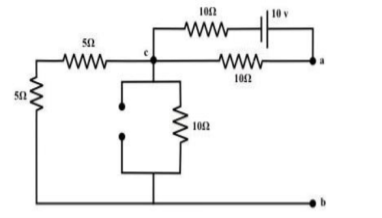
Figure 65: Circuit diagram
No current is flowing through ‘cb’-branch. Vab = 5v (‘a’ is higher potential than ‘b’). Consider only 2 A current source only
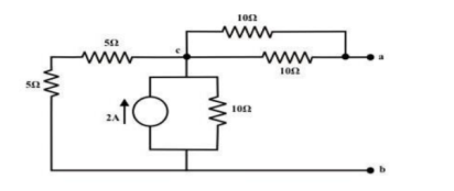
Figure 66: Circuit diagram
To compute Rth
Replace all voltage and current sources by their internal resistance of the circuit.
Rth = Rab = ((5+5)||10) + (10||10) = 5+5 =10Ω
RL = Rth = 10Ω
The maximum power dissipated to RL is
Pmax = Vth 2 / 4 Rth = ¼ 25 /10 = 0.625 watts
Key Takeaways
- Thevenin’s Theorem states that “Any linear circuit containing several voltages and resistances can be replaced by just one single voltage in series with a single resistance connected across the load”.
- Norton’s Theorem states that “Any linear circuit containing several energy sources and resistances can be replaced by a single Constant Current generator in parallel with a Single Resistor”.
- Superposition theorem states that in any linear, active, bilateral network having more than one source, the response across any element is the sum of the responses obtained from each source considered separately and all other sources are replaced by their internal resistance.
- Reciprocity Theorem states that, the value of current due to a single source in any particular branch of circuit is equal to the value of current in the original branch where the source was placed when the source is shifted to that particular branch of circuit.
- Maximum power transfer theorem states that AC voltage source will deliver maximum power to the variable complex load only when the load impedance is equal to the complex conjugate of source impedance.
Applications to DC circuits
All electronics projects and parts for sale on Spark Fun run on DC. Everything that runs off of a battery, plugs into the wall with an AC adapter, or uses a USB cable for power relies on DC.
- Batteries: Batteries, both non-rechargeable and re-chargeable can only supply direct current. The rechargeable batteries also need recharging using direct current.
- Electronic equipment: All equipment like computers, radios, mobile phones, and in fact all electronic equipment uses direct current to power the electronic circuits. Bipolar transistors, FETs and the integrated circuits that use these components all need direct current to power them and will damaged if a reverse polarity is supplied. Although many of these items are powered by AC mains, there is a unit called a power supply within the unit that converts the incoming AC to direct current with the right voltage(s) within the electronic item.
- Some electrical equipment: Although a lot of electrical equipment uses AC, some uses direct current.
- Solar panels: Solar panels used for generating electricity produce direct current directly from the solar panels themselves. When used with AC mains to feed into the mains or supply local AC power for AC supplies, a unit known as an inverter is required to enable the direct current, DC from the solar panels to be converted to AC.
Applications to AC circuits
Home and office outlets are almost always used in AC. This is because generating and transporting AC across long distances and relatively easy. At high voltages like as over 110kV, less energy is lost in electrical power transmission. Higher voltages mean lower currents, and lower currents mean less heat generated in the power line due to resistance. AC can be converted from high voltages easily using transformers.
AC is also capable of powering electric motors. Motors and generators are the exact same device, but motors convert electrical energy into mechanical energy. This is useful for many large appliances like refrigerators, dishwashers, and so on, which run on AC.
Alternating current tends to be used for power distribution. It has the advantage that it can easily be converted to other voltages using a simple transformer - transformers do not work with direct current.
In view of the fact that alternating current is used for the supply system, it is also used in motors, for heating and for many other items without the need for it to be converted to direct current
Transient phenomena are phenomena that exist only for short a while and are not simple periodic functions of time.
Transient currents and voltages: Production of currents and voltages in a circuit in a very short interval of time is called transient currents and voltages. During the transient process, the currents and voltages in the circuit are functions of time.
Growth and decay of current in L-R circuit
(i) Growth of current in L-R circuit.
Consider a circuit consisting of a battery of a steady emf E, an inductance L and a resistance R as shown in Figure.
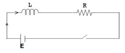
Figure 67: Growth of current in L-R circuit
When the key is suddenly pressed, there is growth of current in the circuit and a back emf is induced. Let I be the current at any instant of time t then
 ……….. (1)
When the current reaches maximum value I0, the back emf

 ……….. (2)
From eqns (1) and (2), we have

 ……….. (3)
Taking (I0 – I) = x
Differentiating with respect to time, we get

Substituting this in eq. (3), we get


Integrating


Where K is constant.
When t = 0, I = 0,


The quantity L/R is called the time constant of the circuit.
Time constant
The quantity R
L has the dimension of time and is called the time constant () of the
L-R circuit.
If L/R = t, then

The time constant L/R of a L-R circuit is the time taken by the current to grow from zero to 0.632 times the maximum value of current - I0 in the circuit. The graph between current and time at the time of the growth of current is shown in figure
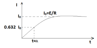
Figure 68: Growth of current in L-R circuit
Decay of current in a circuit containing L and R
When the circuit is broken, an induced emf, equal to -L (dI/dt)is again produced in the inductance L and it slows down and decay to zero. The current in the circuit decays from maximum value I0 to zero.
During the decay, let I be the current at time t. In this case E=0. The emf equation for the decay of current is


Integrating

Where k is constant
When t=0, I=I0


Equation represents the current at any instant t during decay. A graph between current and time during decay is shown in Figure.
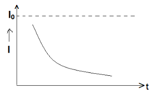
Figure 69: Decay of current in a circuit containing L and R
Time constant

The time constant L/R of a L-R circuit may also be defined as the time in which the current in the circuit falls to 1/e of its maximum value when emf is removed. Figure shows that the growth and decay curves are complementary with each other.
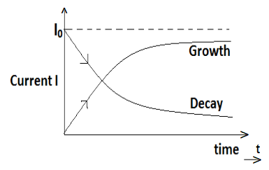
Figure 70: Time constant
Charge and discharge of a capacitor through a resistor
(i) Growth of charge
Consider a circuit consisting of a cell of emf E, a key K, a capacitor C and a resistance R as shown in Figure.
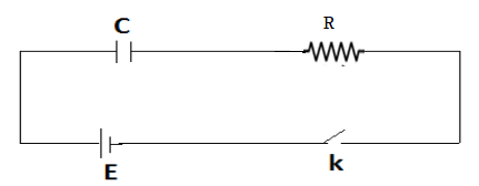
Figure 71: CR Circuit
When the current is started, let q be the instantaneous charge on the condenser and I be the instantaneous current. The emf equation for the CR circuit is

But 
Hence, 


Integrating,

Where K is a constant
Applying the initial condition, When t=0, q=0, -logeq0=K


This is called instantaneous value of the charge at time t. The term CR is called time constant of the circuit.
Time constant
At the end of time t = CR,
The Eq. Becomes


Thus, the time constant may be defined as the time taken by the capacitor to get charged to 0.632 times its maximum value. The growth of charge is shown in Figure.
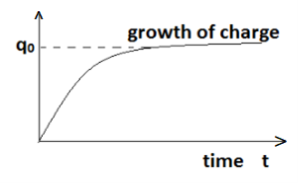
Figure 72: Growth of charge
Decay of charge (Discharging of a capacitor though Resistance)
Let the capacitor having charge q0 be now discharged by opened the key K. The charge flows out of the capacitor. In this case E = 0. The emf equation is


Integrating,

Where K is a constant
Initial condition, when t = 0, q = q0


This is called the instantaneous value of the charge during the discharge. The graph for decay of charge is shown in Figure.
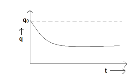
Figure 73: Decay of charge
Time constant: If we put t = CR in Equation, we get q = q0e-1
Ieq = q0 x 1/e, q = 0.368 q0
Hence time constant may also be defined as the time taken by the capacitor to discharge the charge from 0.368 of its maximum value.
Key Takeaways
- Transient phenomena are phenomena that exist only for short a while and are not simple periodic functions of time.
- Transient currents and voltages: Production of currents and voltages in a circuit in a very short interval of time is called transient currents and voltages. During the transient process, the currents and voltages in the circuit are functions of time.
References:
- Theory and Problems of Basic electrical Engineering: Nagrath Kothri
- Electrical technology by B.L.Theraja, A.K.Theraja: S chand publication
- Basic Electrical Engineering: V K Mehta
- Basic Electrical Engineering: S K Sahdev: Pearson publication
- Electrical Safety, Fire Safety engineering S.Rao, Khanna Publication