Unit -1
Maxwell Equations
Maxwell's equations are a set of four equations that together describe the generation and interaction of electric and magnetic fields. These four equations, which embody experimental rules, were used by physicist James Clerk Maxwell to describe electromagnetic fields in the nineteenth century.
These four equations are stated as follows: (1) electric field diverges from electric charge, an expression of the Coulomb force; (2) there are no isolated magnetic poles, but the Coulomb force acts between the poles of a magnet; (3) electric fields are produced by changing magnetic fields, an expression of Faraday's law of induction; and (4) circulating magnetic fields are produced by changing magnetic fields, an expression of Faraday's law of induction. In the metre-kilogram-second (mks) system, the most compact approach to write these equations is in terms of the vector analysis operators div (divergence) and curl—that is, in differential form. In these expressions the Greek letter rho, ρ, is charge density, J is current density, E is the electric field, and B is the magnetic field; here, D and H are field quantities that are proportional to E and B, respectively. The four Maxwell equations, corresponding to the four statements above, are: (1) div D = ρ, (2) div B = 0, (3) curl E = -dB/dt, and (4) curl H = dD/dt + J.
One of the most elegant and concise methods to express the foundations of electricity and magnetism is through Maxwell's equations. Most of the professional relationships in the field can be developed from them. They are not commonly included in an introductory teaching of the subject, except potentially as summary relationships, because of their simple formulation, which encapsulates a high level of mathematical understanding.
These fundamental equations of electricity and magnetism can be used as a springboard for more advanced courses, although they're commonly encountered as unifying equations after studying electrical and magnetic phenomena.
Maxwell's Equations
Integral form in the absence of magnetic or polarizable media:
I. Gauss' law for electricity
II. Gauss' law for magnetism 
III. Faraday's law of induction

IV. Ampere's law
Symbols Used | ||
E = Electric field | ρ = charge density | i = electric current |
B = Magnetic field | ε0 = permittivity | J = current density |
D = Electric displacement | μ0 = permeability | c = speed of light |
H = Magnetic field strength | M = Magnetization | P = Polarization |
Key takeaway:
• Maxwell's four equations explain how electric charges and currents produce electric and magnetic fields, as well as how they interact. Gauss' law describes the relationship between an electric field and the charge(s) that produce it.
• Maxwell's equations are a set of four differential equations that describe classical electromagnetism theoretically: The law of Gauss: An electric field is created by electric charges. Faraday's law states that magnetic fields that fluctuate in time produce an electric field.
1.2.1 Displacement Current: Derivation & Its Properties
In electromagnetic theory, the phenomenon of the magnetic field can be explained concerning a change in the electric field. The magnetic field is produced in the surroundings of the electric current (conduction current). Since the electric current might be in the steady-state or varying state. The concept displacement current depends on the variation of time of the electric field E, developed by the British physicist James Clerk Maxwell in the 19th century. He proved that the displacement current is another kind of current, proportional to the rate of change of electric fields and also explained mathematically. Let’s discuss the displacement current formula and necessity in this article.
1.2.2 What is the Displacement Current?
The sort of current created as a result of the rate of electric displacement field D is known as displacement current. It's a time-varying quantity that Maxwell's equations introduce. It's explained in terms of electric current density units. The law of Ampere circuits introduces it.
Ampere is the SI unit for displacement current (Amp). This dimension can be measured in length units, which can be maximum, minimum, or equivalent to the actual distance travelled from start to finish.
1.2.3 Derivation
Consider the fundamental circuit that gives the displacement current in a capacitor to understand the displacement current formula, dimensions, and derivation of displacement current.
Consider a parallel plate capacitor with a power supply requirement. When power is applied to the capacitor, it begins to charge and there is no current flow at first. The capacitor charges continually and builds above the plates as time passes. A change in the electric field between the plates during the charging of a capacitor over time causes the displacement current.
From the given circuit, consider the area of the parallel plate capacitor = S
Displacement current = Id
Jd = displacement current density
d= €E ie., related to electric field E
€ = permittivity of the medium between the plates of a capacitor
The displacement current formula of a capacitor is given as,
Id= Jd × S = S [dD / dt]
Since Jd = dD/dt
The displacement current will have the same unit and effect on the magnetic field as the conduction current, according to Maxwell's equation.
▽×H=J+Jd
Where,
H = magnetic field B as B=μH
μ = permeability of the medium in between the plates of a capacitor
J = conducting current density.
Jd =displacement current density.
As we know that ▽(▽×H) =0 and ▽. J=−∂ρ/∂t=−▽(∂D/∂t)
By using Gauss’s law that is ▽. D=ρ
Here, ρ = electric charge density.
Hence, we can conclude that, Jd=∂D/∂t displacement current density and it is necessary to balance RHS with LHS of the equation.
1.2.4 Properties
The following are the properties of displacement current: • It is a vector quantity that obeys the continuity property in a closed path. • It varies with the rate of change of current in an electric density field.
• When the current in a wire's electric field is constant, it gives zero magnitudes.
• An electric field's fluctuating time is a factor.
• It had a positive, negative, or zero magnitude with both direction and magnitude.
• Regardless of the path, the length of this can be taken as the shortest distance between the starting and ending points.
• It can be measured in length units.
• It has a minimum, maximum, or equivalent magnitude of displacement to the actual distance from the spot for a certain period.
• It is dependent on the presence of an electromagnetic field.
• When the starting and finishing points are the same, it returns zero.
We previously looked at how scalar potential can be used to solve electrostatic difficulties. After that, we learned how to employ vector potential A to solve magnetostatic problems. Now we'll look at how to solve time-harmonic (electrodynamic) problems using a combination of scalar and vector potentials. This is crucial for bridging the gap between the static domain, in which the frequency is zero or low, and the dynamic regime, in which the frequency is high. It is critical to comprehend electromagnetic field radiation in the dynamic regime. Antennas, communications, sensors, wireless power transfer applications, and many other applications rely on the electrodynamic regime. As a result, understanding how time-varying electromagnetic fields radiate from sources is critical. It's also crucial to know when the static and circuit (quasi-static) regimes are relevant. The circuit regime answers difficulties that have fuelled the microchip industry, therefore knowing when electromagnetic difficulties may be approximated with simple circuit problems and solved using basic rules like KCL and KVL is critical. First of all, we are fundamentally interested in E & B. But essentially, it comes down to the fact that only E and B are physically measurable and so ϕϕ and A are mainly only considered as mathematical constructs, but this isn't always true - they can be conceptualized.
We may rephrase E and B as a combination of a vector potential and a scalar potential using the Helmholtz theorem, which is more of a mathematical construct than a scientific understanding.
According to the theorem, every vector field (which E and B are) may be represented as:
F=−∇ϕ+∇×A
So, we can rewrite E and B as
E=−∇ϕ+∇×A
B=−∇ϕ+∇
However, we know that the curl of the E field is zero under electrostatic conditions. The electric field is conservative in this scenario and is simply determined by the potential gradient. As a result,
E=−∇ϕ
The fact that B =∇×A is a little bit more involved. We know that no magnetic monopoles exist so there can be no sinks or sources so
∇⋅B=0∇
There is also a second part of the Helmholtz theorem which gives that
ϕ(r)=14π∫∫∫∇⋅B|r−r′|dV′
And
A(r)=14π∫∫∫∇×B|r−r′|dV′
We can now see that ϕ(r) must be zero. Which means that
B=∇×A
By working with ϕ and A it can greatly make our mathematical constructs simpler and make it easy for us to calculate the E and B fields. I can't convince you of this immediately, but hopefully you can see how the above expressions look simpler than the Biot Savart law, for instance.
The minus sign in our E expression reflects the fact that positive charges travel from a high potential to a low potential, in the opposite direction of the steepest increase in the potential function. This is a standard procedure. We also know the E field is conservative. You can take any path from point a to point b, and the value of the integral below remains the same:
ϕ(r)=−∫rOE⋅dl
With O denoting the point at which potential is assumed to be zero. Because we don't identify a route, this may cause some misunderstanding, but it won't matter because the E field is conservative. We can put the zero point wherever we like - even add a constant if we want - because we're only interested in the derivative because the E field is the only physically measurable entity.
In most electrostatic conditions, calculating the electric potential rather than the E field directly will be easier. We'll have a B field from Maxwell-Amperes law if we have moving charge. This indicates that the E field's curl is no longer zero.
Electric potential should not be confused with potential energy. The electric potential has a fixed value at any location in space, regardless of the charge you place there, and the electric field is determined by its gradient (which is the force per unit charge, also independent of the actual amount of charge placed at that point). To determine the potential energy (derivation not given) U=qϕ.
Now it's time for you to give your physical interpretation of A. We know that the scalar potential can be interpreted physically, but what makes A unique?
The vector potential can be thought of as a useful mathematical tool with no physical value for most applications, but it does have a physical interpretation. We can observe that A has units of momentum per charge on closer inspection, thus we may think of A as the "momentum per unit charge" held in the electromagnetic field. It's similar to potential energy, except this time it's potential momentum.
Furthermore, in many areas of current physics, the vector potential is an important quantity (superconductivity, Aharonov-Bohm effect, Josephson junctions, SQUIDS, etc.). The canonical momentum of a charged particle in an electromagnetic field is given by p = mv + qA for Lagrangian mechanics students. A can be expressed as a 4-vector in the relativistic formulation of electrodynamics. Both of these values, being 4-vectors, transform between inertial reference frames via Lorentz transformations. It's probably ok to think of it as nothing more than a mathematical convenience until you get across these situations.
1.4.1 Gauge transformations
In terms of scalar and vector potentials, electric and magnetic fields can be represented as follows:

This prescription, however, is not unusual. There are numerous potentials that can produce the same fields. This is not the first time we've seen this issue. It's known as gauge invariance. In Eqs., the most general transformation that leaves the and fields intact is
 (1)
(1)
 (2)
(2)
This is unmistakably a generalization of the gauge transformation we discovered for static fields earlier:
 (3)
(3)
 (4)
(4)
Where  is a constant. In fact, if
  then Eqs. (1) and (2) reduce to Eqs. (3) and (4).
We have complete freedom in selecting the gauge in order to keep our equations as basic as possible. The most reasonable gauge for the scalar potential, as before, is to make it zero at infinity:
 as
as 
The so-called Coulomb gauge was shown to be the best gauge for the vector potential in stable fields:

For non-steady fields, we can still utilize this gauge. The preceding reasoning that the divergence of a vector potential can always be transformed away, is still true. One of the good things about the Coulomb gauge is that when we write the electric field, we can use it to write the magnetic field as well.

The part induced by magnetic fields (i.e., the second term on the right-hand side) is entirely solenoidal, whereas the part induced by charges (i.e., the first term on the right-hand side) is conservative. We already established that a generic vector field can be expressed as the sum of a conservative field and a solenoidal field using mathematics. Now we're discovering that when we split the electric field in this way, the two halves have different physical origins: the conservative component comes from electric charges, while the solenoidal part comes from magnetic fields.
Equation, in addition to the field equation, can be combined.

(Which remains valid for non-steady fields) to give

With the Coulomb gauge condition,  the above expression reduces to

Poisson's equation is all there is to it. As a result, we can write down an expression for the scalar potential created by non-steady fields almost instantaneously. It's the same as our previous expression for the scalar potential generated by steady fields, which was:
 This seemingly simple outcome, however, is profoundly deceiving. A common action at a distance law is Equation. If the charge density at abruptly changes, the potential at reacts rapidly. The entire time-dependent Maxwell's equations, however, only allow information to move at the speed of light, as we will see later (i.e., they do not violate relativity). How do you reconcile these two statements? The important aspect is that the scalar potential cannot be directly measured; instead, it must be inferred from the electric field. The electric field in the time-dependent case is divided into two parts: that which comes from the scalar potential and that which comes from the vector potential. So, just because the scalar potential reacts quickly to a change in charge density over a short distance does not mean the electric field does as well. What actually happens is that a change in the scalar potential part of the electric field is balanced by an equal and opposite change in the vector potential part, resulting in the overall electric field remaining unchanged. This state of affairs remains at least until a light signal from the distant charges reaches the region in question. Because the electric field, not the scalar potential, provides physically accessible information, relativity is not violated.
It is clear that Eq.'s apparent activity at a distance is highly misleading. This clearly shows that in the time-dependent example, the Coulomb gauge is not the best gauge. The so-called Lorentz gauge is a better option:

By similarity with preceding arguments, it can be proven that at every given point in time, it is always possible to perform a gauge transformation that satisfies the above equation. We get Eq. By substituting the Lorentz gauge requirement.

It turns out that this is a three-dimensional wave equation in which information propagates at the speed of light. But, more of this later. Note that the magnetically induced part of the electric field (i.e.,  ) is not purely solenoidal in the Lorentz gauge. In comparison to the Coulomb gauge, this is a minor drawback of the Lorentz gauge. This disadvantage, however, is more than compensated for by other benefits that will become evident shortly. In addition, the fact that the portion of the electric field attributed to magnetic induction changes as the gauge is changed shows that the separation of the field into magnetically induced and charge induced components is not unique in the general case of time-varying fields (i.e., it is a convention).
1.5.1 Boundary Conditions at Interface between Different Media
Now we consider a border medium 1 and 2 interface, as indicated in Fig. For the Gauss box, we may derive the following from Gauss law: the interface inside the box,

In the limit that the Gauss box is very thin

Where vector  means the unit vector pointing from media 1 to 2.

From 

Stokes theorem:


![\includegraphics[width=12cm]{gauss_stokes_box.eps}](https://glossaread-contain.s3.ap-south-1.amazonaws.com/epub/1642692357_4769542.png)
Fig: Gauss and Stokes box
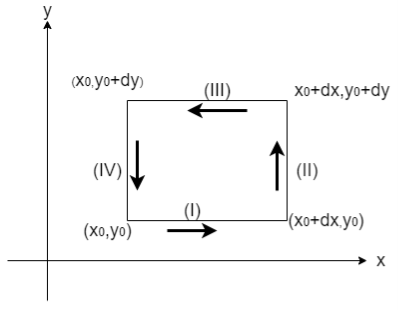
Fig: Stokes theorem
From Eq.3


From Eq.4


 =
=

1.5.2 Boundary conditions for perpendicular field components
The boundary conditions governing the perpendicular components of E¯ and H¯ follow from the integral forms of Gauss’s laws:
 (Gauss’s law for
  )
)
 (Gauss’s law for
  )
)
These equations can be integrated over the surface S and volume V of the thin infinitesimal pillbox in Figure. The pillbox runs parallel to the ground and spans it, with half of it on either side of the line. The pillbox's thickness approaches zero quicker than its surface area S, where S is roughly twice the area A of the box's top surface.
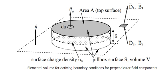
Beginning with the boundary condition for the perpendicular component D⊥, we integrate Gauss’s law over the pillbox to obtain:

Where ρs is the surface charge density [Coulombs m-2]. The subscript s for surface charge ρs distinguishes it from the volume charge density ρ [C m-3]. The pillbox is so thin (δ → 0) that: 1) the contribution to the surface integral of the sides of the pillbox vanishes in comparison to the rest of the integral, and 2) only a surface charge q can be contained within it, where ρs = q/A = lim ρδ as the charge density ρ → ∞ and δ → 0. Thus (2.6.3) becomes D1⊥ - D2⊥ = ρs, which can be written as:

Where n^ is the unit overlinetor normal to the boundary and points into medium 1. Thus, the perpendicular component of the electric displacement overlinetor D¯ changes value at a boundary in accord with the surface charge density ρs.
Because Gauss’s laws are the same for electric and magnetic fields, except that there are no magnetic charges, the same analysis for the magnetic flux density B¯ in (2.6.2) yields a similar boundary condition:

Thus, the perpendicular component of B¯ must be continuous across any boundary.
1.5.3 Boundary conditions for parallel field components
The boundary conditions governing the parallel components of overline E and H¯ follow from Faraday’s and Ampere’s laws:


As shown in Figure, we may integrate these equations around the extended rectangular contour C that crosses the border and has infinitesimal area A. We suppose that the rectangle's entire height is significantly less than its length W, and that circle C is right-hand relative to the surface normal n^a.
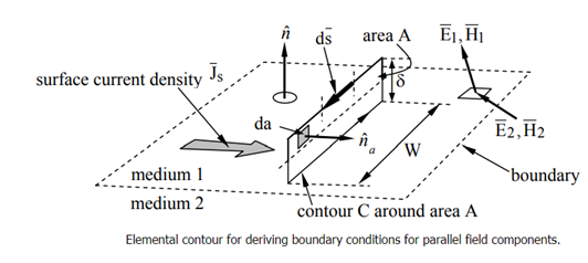
Beginning with Faraday’s law, we find:

Where the integral of B¯ over area A approaches zero in the limit where δ approaches zero too; there can be no impulses in B¯. Since W ≠ 0, it follows from (2.6.8) that E1// - E2// = 0, or more generally:

Thus, the parallel component of E¯ must be continuous across any boundary.
A similar integration of Ampere’s law, (2.6.7), under the assumption that the contour C is chosen to lie in a plane perpendicular to the surface current SJ¯S and is traversed in the right-hand sense, yields:

Where we note that the area integral of ∂D/∂t∂D¯/∂t approaches zero as δ → 0, but not the integral over the surface current JsJ¯s, which occupies a surface layer thin compared to δ. Thus H1//−H2//=JSH¯1//−H¯2//=J¯S, or more generally:

Where n^ is defined as pointing from medium 2 into medium 1. If the medium is nonconducting, Js=0J¯s=0.
A simple static example illustrates how these boundary conditions generally result in fields on two sides of a boundary pointing in different directions. Consider the magnetic fields H1H¯1 and H2H¯2 illustrated in Figure, where μ2≠μ1μ2≠μ1, and both media are insulators so the surface current must be zero. If we are given H1H¯1, then the magnitude and angle of H2H¯2 are determined because H//H¯// and B⊥B¯⊥ are continuous across the boundary, where Bi=μiHiB¯i=μiH¯i. More specifically, H2//=H1//H¯2//=H¯1//,

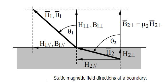
It follows that:
 Thus, θ2 approaches 90 degrees when μ2 >> μ1, almost regardless of θ1, so the magnetic flux inside high permeability materials is nearly parallel to the walls and trapped inside, even when the field orientation outside the medium is nearly perpendicular to the interface. The flux escapes high-μ material best when θ1 ≅ 90°. This phenomenon is critical to the design of motors or other systems incorporating iron or nickel.
If a static surface current JSJ¯S flows at the boundary, then the relations between B1B¯1 and B2B¯2 are altered along with those for H1H¯1 and H2H¯2. Similar considerations and methods apply to static electric fields at a boundary, where any static surface charge on the boundary alters the relationship between D1D¯1 and D2D¯2. Surface currents normally arise only in non-static or “dynamic” cases.
1.5.4 Boundary conditions adjacent to perfect conductors
The four boundary conditions are simplified when one medium is a perfect conductor (σ = ∞) because electric and magnetic fields must be zero inside it. The electric field is zero because otherwise it would produce enormous J=σEJ¯=σE¯ so as to redistribute the charges and to neutralize that E¯ almost instantly, with a time constant ττ =εσ seconds, as shown in Equation.
It can also be easily shown that B¯ is zero inside perfect conductors. Faraday’s law says ∇×E=−∂B/∂t∇×E¯=−∂B¯/∂t so if E¯= 0, then ∂B/∂t=0∂B¯/∂t=0. If the perfect conductor were created in the absence of B¯ then B¯ would always remain zero inside. It has further been observed that when certain special materials become superconducting at low temperatures, any pre-existing B¯ is thrust outside.
The boundary conditions for perfect conductors are also relevant for normal conductors because most metals have sufficient conductivity σ to enable J¯ and ρs to cancel the incident electric field, although not instantly. As discussed in Section 4.3.1, this relaxation process by which charges move to cancel E¯ is sufficiently fast for most metallic conductors that they largely obey the perfect-conductor boundary conditions for most wavelengths of interest, from DC to beyond the infrared region. This relaxation time constant is ττ = ε/σ seconds. One consequence of finite conductivity is that any surface current penetrates metals to some depth δ=2/ωμσ√δ=2/ωμσ, called the skin depth. At sufficiently low frequencies, even sea water with its limited conductivity largely obeys the perfect-conductor boundary condition.
The four boundary conditions for fields close to perfect conductors, as well as the more general boundary condition from which they follow when all fields in medium 2 are zero, are provided below:


Magnetic fields can only be parallel to ideal conductors, while electric fields can only be perpendicular, according to these four boundary criteria. Furthermore, surface currents flowing in an orthogonal direction are always connected with magnetic fields; these currents have a numerical value equal to H. When D points away from the conductor, the sign of is positive, and the perpendicular electric fields are always associated with a surface charge s numerically equal to D.
1.6.1 Wave Equation
A vertical string of length LL that has been stretched firmly between two places at x=0x=0 and x=Lx=L in this part.
We can assume that the slope of the displaced string at any location is minimal since the string has been tightly stretched. So, what exactly does this mean for us? Consider the equilibrium position of a point xx on the string, i.e., the location of the point at t=0. This point will be displaced both vertically and horizontally as the string vibrates; however, if we assume that the slope of the string is small at any point, the horizontal displacement will be very small in comparison to the vertical displacement. As a result, we can now assume that the displacement at any position x on the string will be wholly vertical. So, let's name this change u. (x, t).
We'll suppose, at least at first, that the string isn't perfectly uniform, and that the mass density of the string, (x), is a function of x.
Next, we'll pretend that the string is completely flexible. The string will have no resistance to bending as a result of this. This means that the force imposed by the string on the ends at any location xx will be tangential to the string. This force is known as string tension, and its magnitude is given by T. (x, t)
Finally, we'll use Q (x, t) to represent the vertical component of any force acting on the string per unit mass.
If we suppose that the string's slope is small again, the vertical displacement of the string at any point is given by,
ρ(x)∂2u∂t2=∂∂x (T (x, t) ∂u∂x) +ρ(x)Q (x, t) (1)
Because this is a tough partial differential equation to solve, we'll need to simplify it even more.
We'll start by assuming that the string is perfectly elastic. This means that the magnitude of the tension, T (x, t), is solely determined by the length of the string at x. Remember that we're assuming that the slope of the string at any point is small, which means that the tension in the string will be very close to that of the string in its equilibrium position. The tension can then be assumed to be constant, T (x, t) =T0.
Furthermore, in most circumstances, gravity will be the sole external force acting on the string, and if the string is light enough, the effects of gravity on the vertical displacement will be minimal, implying that Q (x, t) =0. This results in
ρ∂2u∂t2=T0∂2u∂x2
If we now divide by the mass density and define,
c2=T0ρ
We arrive at the 1-D wave equation,
∂2u∂t2=c2∂2u∂x2 (2)
#When we looked at the heat equation in the previous part, he had a variety of boundary conditions; however, in this case, we will just look at one type of boundary condition. The only boundary constraint we shall consider for the wave equation is the required placement of the borders or,
u (0, t) =h1(t)u (L, t) =h2(t)
The start conditions (yes, there will be more than one...) will also differ from what we saw with the heat equation. Because we're dealing with a 2nd order temporal derivative, we'll require two beginning conditions. At any step along the way, we'll supply the string's starting displacement as well as its starting velocity. The starting circumstances are as follows:
u(x,0) =f(x)∂u∂t(x,0) =g(x)
We'll finish this part with the 2-D and 3-D versions of the wave equation for completeness' sake. We won't solve this at any time, but since we already presented the higher-dimensional form of the heat equation (in which we'll solve a specific case), we'll include it here.
The 2-D and 3-D version of the wave equation is,
∂2u∂t2=c2∇2u
Where ∇2 is the Laplacian.
Key takeaway:
The speed of a wave is proportional to the wavelength and indirectly proportional to the period of the wave: v=λT. This equation can be simplified by using the relationship between frequency and period: v=λf.
1.7.1 Propagation in a dielectric medium
Consider an electromagnetic wave propagating over a homogeneous dielectric medium with a dielectric constant of. The dipole moment per unit volume created in the medium by the wave electric field, according to Eqs. (810) and (812), is

In the medium, there are no free charges or currents. There is no bound charge density (due to the uniformity of the medium) and no magnetization current density (since the medium is non-magnetic). However, due to the time-variation of the induced dipole moment per unit volume, there is a polarization current. This current, according to Eq. (859), is provided by

Hence, Maxwell's equations take the form


According to Eqs., the last of the above equations can be rewritten

Since  . Thus, Maxwell's equations for the propagation of electromagnetic waves through a dielectric medium are the same as Maxwell's equations for the propagation of waves through a vacuum (see Sect. 4.7), except that
  , where

Is called the refractive index of the medium in question. Hence, we conclude that electromagnetic waves propagate through a dielectric medium slower than through a
Vacuum by a factor  (assuming, of course, that
  ). This conclusion (which was reached long before Maxwell's equations were invented) is the basis of all geometric optics involving refraction.
1.8.1 Poynting’s Theorem
Despite the appearance of electromagnetic theory's complexity, electromagnetic energy can only be handled in four ways. Electromagnetic energy can take the following forms:
• Stored in an electric field (capacitance);
• Transferred; i.e., transmitted by transmission lines or in waves.
• Inductance (storage in a magnetic field); or
• Has dissipated (converted to heat; i.e., resistance).
Poynting's theorem provides a beautiful representation of energy conservation that connects all of these possibilities. The theorem has substantial applications in the analysis and design of electromagnetic systems once it is understood. Some of them derive from the theorem's derivation, rather than the expected consequence. So, let's get down to business and prove the theorem.
We'll start with a theorem declaration. Consider a volume V that might include any mix of materials and structures. Figure depicts this in a rough manner.
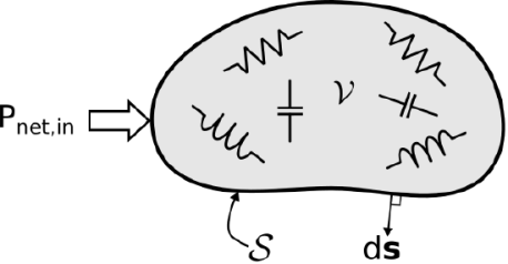
Figure: The fate of power entering a region VV made up of materials and structures capable of storing and dissipating energy is described by Poynting's theorem.
Also keep in mind that power is the rate of change of energy over time. After that, you should:
 (3.1.1)
Pnet,in represents the net power flow into V, PE represents the power associated with energy storage in electric fields within V, PM represents the power associated with energy storage in magnetic fields inside V, and P represents the power dissipated (converted to heat) in V.
1.8.2 Derivation of the Theorem
We begin with the differential form of Ampere’s law:
∇×H=J+∂∂tD (3.1.5)
Taking the dot product with EE on both sides:
E⋅(∇×H) =E⋅J+E⋅∂∂tD (3.1.6)
Let’s deal with the left side of this equation first. For this, we will employ a vector identity from Appendix B.3:
∇⋅(A×B) =B⋅(∇×A)−A⋅(∇×B)
This identity states that for any two vector fields F and G,
∇⋅(F×G) =G⋅(∇×F)−F⋅(∇×G) (3.1.7)
Substituting E for F and H for G and rearranging terms, we find
E⋅(∇×H) =H⋅(∇×E)−∇⋅(E×H) (3.1.8)
Next, we invoke the Maxwell-Faraday equation:
∇×E=−∂∂tB (3.1.9)
Using this equation to replace the factor in the parentheses in the second term of Equation 3.1.8, we obtain:
E⋅(∇×H) =H⋅(−∂∂tB)−∇⋅(E×H) (3.1.10)
Substituting this expression for the left side of Equation 3.1.6, we have
−H⋅∂∂tB−∇⋅(E×H) =E⋅J+E⋅∂∂tD (3.1.11)
Next, we invoke the identities of Equations 3.1.3 and 3.1.4 to replace the first and last terms:
−12∂∂t(H⋅B)−∇⋅(E×H) =E⋅J+12∂∂t(E⋅D)
Now we move the first term to the right-hand side and integrate both sides over the volume VV:
−∫V∇⋅(E×H) dv=∫VE⋅J dv+∫V12∂∂t(E⋅D) dv+∫V12∂∂t(H⋅B) dv
The left side may be transformed into a surface integral using the divergence theorem:
∫V∇⋅(E×H) dv=∮S(E×H) ⋅ds (3.1.12)
Where SS is the closed surface that bounds V and ds is the outward-facing normal to this surface, as indicated in Figure. Finally, we exchange the order of time differentiation and volume integration in the last two terms:
−∮S(E×H) ⋅ds=∫VE⋅J dv+12∂∂t∫VE⋅D dv+12∂∂t∫VH⋅B dv (3.1.13)
Equation 3.1.1. is Poynting’s theorem. Each of the four terms has the particular physical interpretation identified in Equation 3.1.1, as we will now demonstrate.
1.8.3 Poynting vector
The Poynting vector, which is named after John Henry Poynting, is used to show the energy flux density of an electromagnetic field. The Poynting vector is defined as the result of the vector product of the electric and magnetic components of the field [JAC06]:
(2.22) S→=E→×H→
The Poynting vector is measured in watts per square metre (W m2) since it measures the field's energy flux density. As a result, the Poynting vector gives information about the EM field's propagation direction as well as information about the EM field's energy transport direction. Figure depicts the Poynting vector.
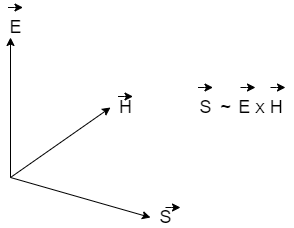
Figure: Poynting vector
The direction of the Poynting vector is identical to the direction of the light beam as normal vector of the plane produced by the electric and magnetic field vectors, as we will see in the discussion of ray optics. The Poynting vector relates to the ray's density according to its physical dimension of watts per area.
Because electromagnetic waves are three-dimensional, it's usually more useful to talk about their energy density (energy per volume). The sum of the energy density of the electric field and the energy density of the magnetic field is the total energy density of the electromagnetic wave.
Electromagnetic waves contain energy, as anyone who has used a microwave oven knows. This energy can be felt, for example, in the warmth of the summer sun. It can also be subtle, like the unnoticed energy of gamma rays, which can kill living cells.
By virtue of their electric and magnetic fields, electromagnetic waves introduce energy into a system. These fields can exert forces on the system's charges and hence do work on them. Regardless of whether an electromagnetic wave is absorbed or not, it contains energy. The fields transfer energy away from a source once they've been produced. If some energy is absorbed later, the field strengths are reduced, and whatever is left travels on.
Clearly, the stronger the electric and magnetic fields are, the more work they can accomplish and the more energy the electromagnetic wave can transport. The greatest field intensity of the electric and magnetic fields is the amplitude in electromagnetic waves. The wave amplitude determines the wave energy.
The amount of energy transported by a wave is determined by its amplitude. Doubling the E and B fields quadruples the energy density u and the energy flux uc in electromagnetic waves.
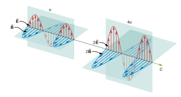
The electric and magnetic fields satisfy the equations for a plane wave flowing in the positive x-axis with the phase selected so that the wave maximum is at the origin at t=0.
The sum of the energies of the electric and magnetic fields is the energy in any portion of an electromagnetic wave. The sum of the energy density from the electric field and the energy density from the magnetic field is this energy per unit volume, or energy density u. Both field energy densities' expressions were discussed. We get Capacitance Inductance from Capacitance Inductance.

The expression  then shows that the magnetic energy density
  and electric energy density are equal, despite the fact that changing electric fields generally produce only small magnetic fields. The equality of the electric and magnetic energy densities leads to

In a similar way to how waves move, the energy density moves with the electric and magnetic fields.
By considering a tiny time interval t, we may determine the rate of energy transport. The energy stored in a cylinder with a length ct and a cross-sectional area A flow through the cross-sectional plane in the interval depicted in (Figure).
The electromagnetic wave's energy uact is held in the electric and magnetic fields in the volume act, and it flows through the region A in time.
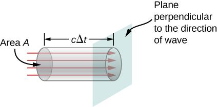
In time t, the energy travelling through area A is
The energy flux, represented by S, is the energy per unit area per unit time travelling through a plane perpendicular to the wave. It may be computed by dividing the energy by the area A and the time interval.
The flux of energy through any surface, in general, is influenced by the surface's direction. To account for the direction, we create a vector known as the Poynting vector, which has the following definition:
In the direction perpendicular to both vectors, the cross-product of E and B points. Return to the previous step to validate that the direction of S is that of wave propagation, not its inverse. It's worth noting that Lenz's and Faraday's laws imply that the electric field at x is bigger than at X+X when the magnetic field depicted is growing in time. At the given time and location, the electric field decreases as x increases. Because electric and magnetic fields are proportional, the electric field must grow in time in tandem with the magnetic field. This is only conceivable if the wave is propagating to the right in the diagram, in which case the relative orientations demonstrate that the electromagnetic wave is propagating in a specified direction.
The energy flux at any given location fluctuates over time, as shown by replacing u.
Because visible light has such a high frequency, the energy flux for visible light through any area is a rapidly varying quantity on the order of the order of the order of the order of the order of the order of the order of the order of the order of the order of the order of the order of the order of the order of Most measuring instruments, including our eyes, only detect an average over a large number of cycles. The intensity I of the electromagnetic wave is the power per unit area, and the temporal average of the energy flux is the intensity I of the electromagnetic wave. It may be represented by taking the cosine function in (Figure) and averaging it over one entire cycle, which is the same as time-averaging over multiple cycles (here, T is one period):
We can either evaluate the integral or notice that because the sine and cosine differ only in phase, the average over a full cycle for and is the same.

The time-averaging operation is represented by the angle brackets. In vacuum, the intensity of light travelling at speed c is found to be

In terms of maximal electric field strength, which is also the amplitude of the electric field The relationship is created using algebraic manipulation.

Where the maximal magnetic field strength is the same as the magnetic field amplitude. It's useful to have another formulation for in terms of both electric and magnetic field intensities. Substituting the fact that the preceding phrase is now

Because the three equations are essentially just various versions of the same result, we can select whichever of the three equations is most convenient: A wave's energy is proportional to its amplitude squared. Furthermore, because these equations are founded on the assumption that electromagnetic waves are sinusoidal, the peak intensity is double that of the average intensity; in other words, the peak intensity is double that of the average intensity.

An expression for the energy density associated with electromagnetic vector fields occupying a volume including free space and material may be adduced from the two curl equations of Maxwell, ∇ × E + ∂B ∂t = 0
(1) ∇ × H − ∂D ∂t = J
(2) where Eq. 1 is the Faraday-Law relation between electric field E and magnetic induction field B while Eq. 2 shows Ampere’s Law relating the magnetic field H, displacement field D, and current density J. A standard text book development [18] leads to ∇ · (E × H) + E · J = −E · ∂D ∂t − H · ∂B ∂t.
(3) The right side of Eq. 3 clearly reflects the time rate of decreasing energy density; but in order to achieve a more geometrical interpretation of the left side of Eq. 3, we integrate both sides over the considered spatial volume and use the divergence theorem to convert volume integration of the first term on the left to a surface integral. Z S (E × H) · n dA = − Z V E · J dV − Z V E · ∂D ∂t + H · ∂B ∂t dV.
(4) It is clear that the second term on the right-side Eq. 4 represents the rate of decrease of field energy contained in the volume. The first term on the right is a volume integral over the scalar product of the E-field and current density within the volume. If we assume no current sources within the volume, the E-field can be written in terms of the current density and the material conductivity σ as σE = J. The integrand of the first term on the right side of Eq. 4 is then written as J 2/σ and interpreted as the dissipative “Joule heating” or “ohmic 3 loss” within the volume. The term on the left therefore expresses the total decrease in energy density (radiative and dissipative). According to Poynting’s theorem this term represents the flow of electromagnetic energy through the surface S enclosing the volume V. The vector product of E and H is termed the Poynting vector S and we write Z S S · n dA = − Z V ∂u ∂t dV.
(5) where u is the total decrease of energy density–ohmic losses when they are present as well as loss from the radiating field itself. In free space or in nonconducting dielectric media we have Z S (E × H) · n dA = Z S S · n dA = − Z V E · ∂D ∂t + H · ∂B ∂t = − Z V ∂u ∂t dV.
(6) or in differential form ∇ · S = − E · ∂D ∂t + H · ∂B ∂t = − ∂u ∂t.
(7) We are usually interested in the absolute value of the energy flow across the bounding surface; and, for harmonically oscillating waves, the average over an optical cycle. We have then, hSi = 1 2 < (E × H∗).
(8) and h∇ · Si = = 1 4 E · ∂D∗ ∂t + H · ∂B∗ ∂t = ∂u ∂t.
(9) Equation 9, the optical-cycle average of the time rate of change of the energy density, is the starting point for our discussion of the energy density in material media subject to harmonic electromagnetic fields with frequencies covering the range from near-UV to near-IR spectral region. The energy density, averaged over an optical cycle, of an electromagnetic field oscillating at frequency ω in a nonmagnetic material media characterized by permittivity = 0r and permeability µ0 is given by < u > = 1 4 [E · D∗ + H · B ∗] = 1 4 (ω)|E 2 | + µ0|H2 | 4 and with |H| = s (ω) µ0 |E|.
(10) we have < u >= 1 2 (ω)|E| 2 = 1 2 E · D∗.
(11) The relative permittivity r (dielectric constant) may be complex with a real part 0 r and an imaginary part 00 r. The total power density, Eq. 9, with the help of Eq. 10, can now be written < W(t) >= ∂u ∂t = 1 2 1 2 (E + E ∗) · 1 2 ∂D ∂t + ∂D∗ ∂t.
Key takeaway:
● The formula for the energy stored in a magnetic field is E = 1/2 LI2. The energy stored in a magnetic field is equal to the work needed to produce a current through the inductor. Energy is stored in a magnetic field. Energy density can be written as uB=B22μ u B = B 2 2 μ.
● The total energy density is equal to the sum of the energy densities associated with the electric and magnetic fields: When we average this instantaneous energy density over one or more cycles of an electromagnetic wave, we again get a factor of ½ from the time average of sin2(kx - t).
References:
1. Classical Electrodynamics by J.D. Jackson (Willey)-2007
2. Foundation of electromagnetic theory: Ritz and Milford (Pearson)-2008
3. Electricity and Magnetism: D C Tayal (Himalaya Publication)-2014
4. Optics: A.K.Ghatak (McGraw Hill Education)- 2017
5. Electricity and Magnetism: Chattopadhyaya, Rakhit (New Central)-2018