Unit - 3
EM Wave in Bounded Media
It's important to distinguish between boundary and interface conditions. The space in which the electromagnetic field is calculated must be constrained by some boundaries for numerical calculations. This is accomplished by assuming physically correct and numerically solvable in finite time boundary conditions. The boundary conditions may revert to a simple interface condition in some cases. A fully reflecting (electric wall) boundary is the most common and straightforward example, in which the outer medium is treated as a perfect conductor. It gets more complicated in some cases: for instance, reflection-less (i.e., open) boundaries are simulated as a perfectly matched layer or magnetic wall that does not resume to a single interface.
Intersection of dielectric media Consider a planar dielectric interface between two media. A plane wave strikes medium 1 at an oblique angle. The interface plane is the plane that separates the two media. The propagation vector is contained in the plane of incidence, which is perpendicular to both the interface plane and the wave's phase planes.
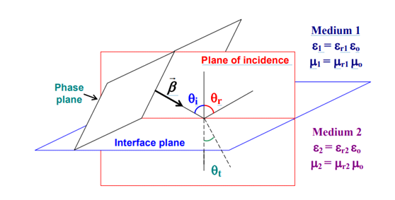
There are two elementary orientations (polarizations) for the electromagnetic fields:
Polarization in the Perpendicular Direction: The magnetic field is parallel to the plane of incidence, while the electric field is perpendicular to it. Transverse Electric (TE) modes are used to configure the fields.
Polarization in the same direction: The electric field is parallel to the plane of incidence, while the magnetic field is perpendicular to it. Transverse Magnetic (TM) modes are used to configure the fields. By superimposing two waves with perpendicular and parallel polarization, any plane wave with general field orientation can be created.
Reflection and refraction at a dielectric boundary
An electromagnetic wave of real (positive) frequency can be written


The wave-vector, k, indicates the direction of propagation of the wave, and also its phase-velocity,  , via
, via

Since the wave is transverse in nature, we must have  . Finally, the familiar Maxwell equation

Leads us to the following relation between the constant vectors  and
and  :
:

Here,  is a unit vector pointing in the direction of wave propagation.
Suppose that the plane  forms the boundary between two different dielectric media. Let medium 1, of refractive index
  , occupy the region
  , whilst medium 2, of refractive index
  , occupies the region
 . Let us investigate what happens when an electromagnetic wave is incident on this boundary from medium 1.
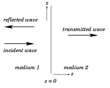
Consider, first of all, the simple case of incidence normal to the boundary. In this case, for the incident and transmitted waves, and
  for the reflected wave. Without loss of generality, we can assume that the incident wave is polarized in the
  -direction. Hence, using Eq. (1214), the incident wave can be written


Where  is the phase-velocity in medium 1, and
  . Likewise, the reflected wave takes the form


Finally, the transmitted wave can be written


Where  is the phase-velocity in medium 2, and
For the case of normal incidence, the electric and magnetic components of all three waves are parallel to the boundary between the two dielectric media. Hence, the appropriate boundary conditions to apply at  are
are


The latter condition derives from the general boundary condition  , and the fact that
  in both media (which are assumed to be non-magnetic).
Application of the boundary condition (1221) yields
 (1223)
Likewise, application of the boundary condition (1222) gives

Or

Since  Equations (1223) and (1225) can be solved to give


As a result, we've calculated the amplitudes of the reflected and transmitted waves in terms of the incident wave's amplitude.
It can be seen, first of all, that if then
then  and
and  In other words, if the indices of refraction of the two media are the same, there is no reflection at the boundary between them, and the transmitted wave has the same amplitude as the incident wave. If there is some reflection at the boundary, on the other hand. In fact, the reflected wave's amplitude is roughly proportional to the difference between
  and
and  . This has significant practical implications. Because of the different refractive indices of air and glass, some of the light incident at an air/glass boundary is reflected, we can only see a clean pane of glass in a window. When glass is submerged in water, as is well known, it becomes much more difficult to see. Because the refractive indices of glass and water are nearly identical, light incident on a water/glass boundary is reflected very little.
According to Eq. (1226),  when
when  . The negative sign indicates a
  phase-shift of the reflected wave, with respect to the incident wave. We conclude that there is a
  On reflection from a boundary with a medium with a higher refractive index, the reflected wave shifts in phase relative to the incident wave. On the other hand, there is no phase shift on reflection from a boundary with a lower refractive index medium.
In the -direction, the mean electromagnetic energy flux, or intensity, is simply

The ratio of the intensities of the reflected and incident waves is defined as the coefficient of reflection, R:

Similarly, the transmission coefficient, T, is the ratio of the transmitted and incident wave intensities:

Equations (1226), (1227), (1229), and (1230) yield


Note that  . In other words, any wave energy which is not reflected at the boundary is transmitted, and vice versa.
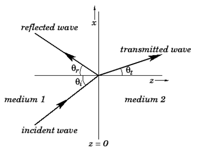
Consider the case of oblique incidence to the boundary (see above Fig.). Assume that the incident wave forms an angle with the normal to the boundary, while the reflected and transmitted waves form angles with the normal to the boundary and
and  , respectively.
The incident wave can be written


The reflected and transmitted waves have analogous expressions. Because the electric and magnetic components of the wave fields are no longer necessarily parallel to the boundary in the case of oblique incidence, the boundary conditions (1221) and (1222) at  must be supplemented by the additional boundary conditions


Equation (1235) derives from the general boundary condition 
Both components of the magnetic field are continuous at the boundary, as shown by Eqs. (1222) and (1236). As a result, we can write

At  . Given that
  and
and  are constant vectors, the only way in which the above equation can be satisfied for all values of
  and is if

Throughout the  plane. This, in turn, implies that

And

It immediately follows that if  then
then  . In other words, if the incident wave lies in the
  -
- plane then the reflected and transmitted waves also lie in the
  -
- plane. Another way of putting this is that the incident, reflected, and transmitted waves all lie in the same plane, known as the plane of incidence. This, of course, is one of the laws of geometric optics. From now on, we shall assume that the plane of incidence is the
 plane.
Now,  and
and  . Moreover,

With similar expressions for  and
and . Hence, according to Eq. (1239),

Which implies that  . Moreover,

The above expressions, of course, correspond to the laws of reflection and refraction, respectively.
We must consider two independent wave polarizations separately in the case of oblique incidence. All wave electric fields are perpendicular to the plane of incidence in the first polarization, while all wave magnetic fields are perpendicular to the plane of incidence in the second.
Let's take a look at the first wave polarization. Unit vectors in the propagation directions of incident, reflected, and transmitted waves can be written as follows:


The constant vectors associated with the incident wave are written


Eq. Has been used in the following cases: (1214). The constant vectors associated with reflected and transmitted waves are also constant.


And


Respectively.
Now, the boundary condition (1221) yields  or
or
 (1253)
Likewise, the boundary condition (1236) gives  , or
, or
 (1254)
However, using Snell's law, (1243), the above expression reduces to Eq. (1253). Finally, the boundary condition (1222) yields  , or
, or

It is convenient to define the parameters

And

Equations (1253) and (1255) can be solved in terms of these parameters to give


These relations are known as Fresnel equations.
The wave intensity in the  -direction is given by

Hence, the coefficient of reflection is written

Whereas the coefficient of transmission takes the form

Note that it is again the case that 
Let's take a look at the second wave of polarization. Constant vectors associated with incident, reflected, and transmitted waves are written in this case.
 (1267)
 (1268)
And
 (1265)
 (1266)
And
 (1267)
 (1268)
Respectively. The boundary condition (1222) yields  , or
, or

Likewise, the boundary condition (1221) gives  , or
, or

Finally, the boundary condition (1235) yields  , or
, or

Making use of Snell's law, and the fact that  =
= , the above expression reduces to Eq. (1269).
Solving Eqs. (1239) and (1270), we obtain
 (1272)
 (1273)
The associated coefficients of reflection and transmission take the form
 (1274)
 (1275)
Respectively. As usual,  .
.
It's worth noting that the Fresnel equations (1258) and (1259) for wave polarization with an electric field parallel to the boundary differ from the Fresnel equations (1272) and (1273) for wave polarization with a magnetic field parallel to the boundary at oblique incidence. This means that the reflection and transmission coefficients for these two wave polarizations are generally different.
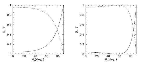
Figure shows the coefficients of reflection (solid curves) and transmission (dashed curves) for oblique incidence from air ( ) to glass (
 ). The wave polarisation with the electric field parallel to the boundary is shown on the left, while the wave polarisation with the magnetic field parallel to the boundary is shown on the right. In general, as the angle of incidence increases, the coefficient of reflection increases and the coefficient of transmission decreases. However, there is a specific angle of incidence for the second wave polarization, known as the Brewster angle, at which the reflected intensity is zero. For the first wave polarization, there is no similar behavior.
The Brewster angle corresponds to the condition, according to Eq. (1272).

Or

Where use has been made of Snell's law. The above expression reduces to

or  . Hence, the Brewster angle satisfies

When unpolarized light is incident at the Brewster angle on an air/glass (say) boundary, the reflected beam is 100% plane polarized.
Key takeaway:
* When a uniform plane wave is incident normally on the planar interface between a perfect dielectric, of parameters € and u, and a perfect conductor, the simplest case of wave reflection occurs.
* The incident wave induces currents and charges only on the perfect conductor's surface.
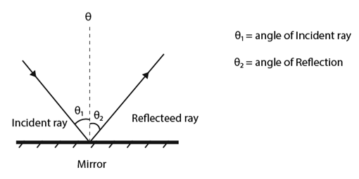
3.3.1 What is Law of Reflection?
Definition:
• The angle of the reflected ray is equal to the angle of the incident ray when reflected from a smooth surface with respect to the normal to the surface, which is a line perpendicular to the surface at the point of contact, according to the law of reflection.
• At the point of contact of the incident ray, the reflected ray is always in the plane defined by the incident ray and the normal to the surface.
• The law of reflection can be used to explain the images produced by plane and curved mirrors.
Law of reflection is defined as:
The angle of reflection is equal to the angle of incidence when light rays fall on a smooth surface, and the incident ray, reflected ray, and normal to the surface all lie in the same plane.
3.3.2 Law of Reflection Formula:
The law of reflection formula is given as:

Where,
• θi is the angle of incidence
• θr is the angle of reflection
3.3.3 Law of Refraction
The law of refraction, also known as Snell's law, governs how light rays behave as they pass through a sharp interface between two transparent dielectric media.
As shown in Fig. Below, a light ray is incident on a plane interface between two transparent dielectric media, labelled 1 and 2. The incident ray, the refracted ray, and the normal to the interface all lie in the same plane, according to the law of refraction. In addition,

Where  is the angle subtended between the incident ray and the normal to the interface, and
  is the angle subtended between the refracted ray and the normal to the interface. The quantities
  and
and  The refractive indices of media 1 and 2 are referred to as such. As a result of the law of refraction, a light ray always deviates more towards the normal in the optically denser medium: that is, the medium with a higher refractive index. Note that
  in the figure. The law of refraction also applies to non-planar interfaces, as long as the normal to the interface at any given point is understood to be the normal to the interface's local tangent plane at that point.
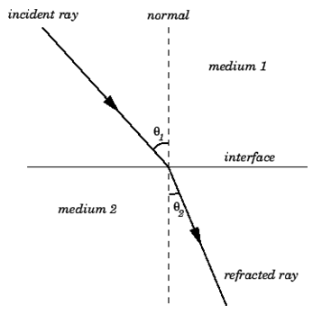
Figure: The law of refraction.
By definition, the refractive index  of a dielectric medium of dielectric constant
  is given by

Table shows the refractive indices of some common materials (for yellow light of wavelength =589nm).
Table: Refractive indices of some common materials at  nm.
nm.
Material |  |
Air (STP) | 1.00029 |
Water | 1.33 |
Ice | 1.31 |
Glass: |
|
Light flint | 1.58 |
Heavy flint | 1.65 |
Heaviest flint | 1.89 |
Diamond | 2.42 |
The fact that the speed with which light propagates through a dielectric medium is inversely proportional to the medium's refractive index gives rise to the law of refraction. In fact,

In a vacuum, what is the speed of light? Consider two parallel light rays, and, which are incident at an angle to the normal at the interface between two dielectric media, 1 and 2. Let and be the refractive indices of the two media, with and being the refractive indices of the two media, respectively. From Fig. 58, it is clear that ray must move from point to point in medium 1 in the same time interval as ray moves between points and in medium 2. Now, the speed of light in medium 1 is, while it is in medium 2. As a result, the length is determined by, whereas the length is determined by. By means of trigonometry,

And

Hence,
 (346)
(346)
Which can be rearranged to give Snell's law. Note that the lines  and
and  represent wave-fronts in media 1 and 2, respectively, and, therefore, cross rays
  and
and  at right-angles.
Key takeaway:
• Light is reflected, or diffused, in many different directions when it strikes different parts of a rough surface at different angles.
• A mirror reflects light at specific angles due to its smooth surface (in comparison to the wavelength of light).
• The light reflected off a mirror appears to come from a specific direction, as determined by the law of reflection.
3.4.1 Fresnel Equations—Perpendicular E field
Augustin Fresnel (1820s) was the first to make this calculation.
First, we'll look at the case of s-polarization.
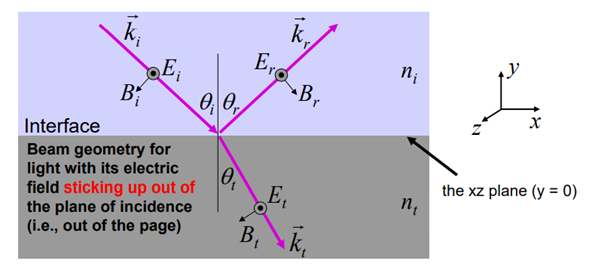
3.4.2 Reflection and Transmission for Perpendicularly Polarized Light
Keeping only the complex amplitudes and ignoring the rapidly varying parts of the light wave:


But  and
and 
Substituting into the second equation

Substituting for  using
using


3.4.3 Fresnel Equations—Parallel electric field
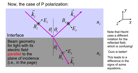
To achieve the reflected wave, the reflected magnetic field must point into the screen. “Into the screen” is indicated by the x with a circle around it.
3.4.4 Reflection & Transmission Coefficients for Parallel Polarized Light
For parallel polarized light, 
And 
Solving for  yields the reflection coefficient

Analogously, the transmission coefficient  is
is

For parallel polarized (p-polarized) light, these equations are known as the Fresnel Equations.
3.5.1 What is Brewster’s Law?
When unpolarized light of a known wavelength is incident on a transparent substance surface, the angle of incidence whose tangent is the refractive index of the substance for the wavelength experiences maximum plan polarization.
Brewster's law describes the relationship between light waves at their maximum polarization angle. Sir David Brewster, a Scottish physicist, proposed the law in 1811, and it is named after him. The law states that at a certain angle, p-polarized rays vanish completely on different glasses.
Brewster's angle is another name for the polarization angle. It is the angle of incidence at which a ray of light with p-polarization passes through a transparent dielectric surface without reflection. While unpolarized light is transmitted at this angle, light is reflected from the surface.
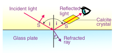
Brewster discovered that the medium's refractive index is numerically equal to the tangent angle of polarization.

Where,


From Snell’s Law:

From Brewster’s Law:

Comparing both formulas: 1 and 2


As, is also equal to the
  . Therefore, the reflected and the refracted rays are at right angles to each other.
3.5.2 Relation Between Brewster Angle and Critical Angle
Brewster’s angle is given as:


The critical angle is given as:


But we know that,


Therefore,

Consider the following two half spaces (deep ocean on top of earth, for example). When a wave of unit amplitude strikes the boundary, a transmitted wave of amplitude t and a reflected wave of amplitude c are produced, as shown in Figure below.
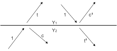
Figure: Waves incident, reflected c, and transmitted t at an interface.
T and c have a very straightforward relationship. Pressure, material displacement, traction, or tangential electric or magnetic fields are all physical properties of wave amplitudes. On both sides of the boundary, these physical variables must have the same value. This means that the transmitted wave must be equal to the sum of incident and reflected waves.


The transmission coefficient t can be greater than unity if the reflection coefficient c is positive or negative. It might surprise you to learn that t can be greater than unity. There are no physical laws that are broken in this process. At the beach, we see waves approaching the shore, which grow in size as they get closer. The energy of a wave is not solely determined by its height. Depending on the medium in which the wave is measured, energy equals the squared wave amplitude multiplied by a proportionality factor Y. The statement that the energy before incidence equals the energy after incidence is true if the top medium's factor is Y1 and the bottom medium's factor is Y2.
 (3)
(3)
Solving for c leads us to


The upgoing and down going wave variables in acoustics can be normalized to either pressure or velocity. The impedance I is the scale factor multiplied by velocity squared when measuring velocity. The admittance Y is the scale factor used to measure pressure.
If Y1 and Y2 are swapped, the wave c' that reflects when energy is incident from the other side is obtained from (4). Thus

A perfectly reflecting interface is one that allows no energy to pass through it. This happens when t = 0 or c = -1, as well as when t = 2 or c = +1. To see this, look at Figure on the left.

When Y1 = Y2, 100 percent of the incident energy is transmitted, but when Y1 and Y2 are very different, the percentage of transmission is very small.
Waves are typically described using two types of variables, both of which can be continuous at a material discontinuity. Pressure, tension, voltage, potential, stress, and temperature are examples of scalars. The other is a vector, of which the vertical component is used. Velocity, stretch, electric current, displacement, and heat flow are examples of the latter. A tensor is occasionally used as a wave variable. When one of the motion components vanishes as a boundary condition, the boundary is often described as rigid. When the pressure or potential disappears, the boundary is often referred to as "free." Waves with unit magnitude reflection coefficients are reflected by rigid and free boundaries.
The goal is to establish fundamental mathematical properties of waves in layers while avoiding specialization in any one physical type of wave. Differential equations exist for each physical problem. In depth z, these equations are Fourier transformed over x and y, resulting in coupled ordinary differential equations. In FGDP, this analytical process is explained in greater depth. An eigenvector analysis is the next step, which connects the physical variables to our abstract up- and down-going waves U and D. We'll look at one specific example, acoustic waves, to better understand boundary conditions.
We have pressure P and the vertical component of parcel velocity W (not to be confused with wave velocity v) in acoustics. The acoustic pressure P is equal to the product of U and D. The minus sign in the definition of W is due to the fact that vertical velocity W changes sign when the z axis changes sign (up and down). (The scaling factor Y comes from the eigenvector analysis.)


These definitions are easily inverted.


Because of the large contrast between air and water, the sea surface is nearly a perfect reflector for sound waves in the ocean. This interface is a free surface if it is idealized to a perfect reflector. We have D = -U at the surface because the pressure vanishes on a free surface, so the reflection coefficient is -1, as shown in Figure below.
Figure shows A waveform R(Z) reflecting at the surface of the sea. Pressure equal to U + D vanishes at the surface. The vertical velocity of the surface is proportional to D - U. Theoretically, waves are observed by measuring W at the surface.
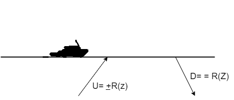
In theory, we should measure W at the water's surface. We usually measure pressure P a few metres below the free surface in practice.
The pressure normally disappears at the sea surface, but if we want to cause an impulsive disturbance, we can temporarily change the pressure to 1, for example. At t=0, this 1 denotes a constant frequency function that is an impulsive function of time. Figure shows the subsequent waves, with the upcoming wave -R(Z) being a result of both the down going 1 and the down going +R. (Z). D - U = 1 + 2R is the vertical component of the sea surface velocity W due to the source and the resulting acoustic wave (Z).
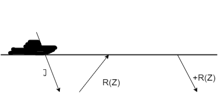
Figure: A down going disturbance 1 is followed by an upgoing reflected wave -R(Z), which reflects back down as R. (Z). D + U = 1 + R - R = 1 is the pressure at the surface.
A high-quality mirror can reflect more than 90% of the light that strikes it while absorbing the remainder. However, having a mirror that reflects all of the light that falls on it would be beneficial. Surprisingly, we can achieve total reflection by manipulating a refraction aspect.
Consider what happens when a ray of light collides with the surface of two materials, as in below Figure a. The light is refracted in part and reflected in part as it passes through the boundary. The ray bends away from the perpendicular if the index of refraction of the second medium is less than that of the first, as shown in the figure below. (Because n1 > n2, the refraction angle is greater than the incidence angle—that is, 1 > 2.) Consider what happens as the incident angle gets wider. This causes θ2 to increase also. As shown in Figure b, the angle of refraction 2 can be as large as 90o. The incident angle 1 that produces a 90o angle of refraction is defined as the critical angle c for a combination of materials. To put it another way, c is the incident angle for which 2 = 90o. Figure c shows that if the incident angle 1 is greater than the critical angle, all of the light is reflected back into medium 1, a condition known as total internal reflection.
The incident angle θ1 that produces an angle of refraction of 90º is called the critical angle, θc.
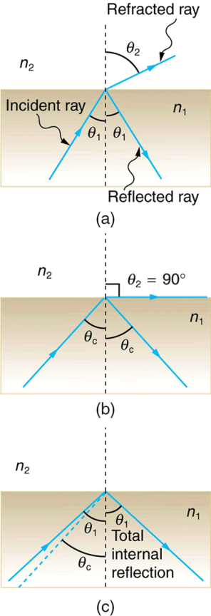
Figure: Aluminum (black line), silver (red line), gold (blue line), and copper reflectance spectra (green line).
Key takeaway:
• Metals have a high reflectivity, refracting nearly all wavelengths in the visible spectrum. As a result, a material's Reflectance (R) can be defined as the efficiency with which it reflects incident light.
• The most common mirror coatings are metals. Aluminum and silver layers are frequently used due to their reflectivity.
• Silver is the most reflective colour in the visible spectrum, reflecting 95% of the light it encounters. Even though aluminium is slightly less reflective, it can still reflect 90% of light.
Evanescent waves are electromagnetic waves that do not spread and are spatially concentrated in the region of the source, according to electromagnetic theory. Many scenarios result in evanescent waves. Total internal reflection of light is one of them (TIR). In TIR, some light (source of evanescent waves) is produced in the rarer media near the medium interface when a light is incident from the denser medium at the medium boundary, coupled with reflected light travelling in the same medium.
As a result, light from free space that strikes a bent section of an optical fibre can be coupled into the fibre using the route retracing approach. In fingerprint scanning and binoculars, evanescent waves are used.
Light is incident from a material with a higher refractive index n1 onto an interface with a substance having a lower refractive index n2 for internal reflection. Snell's law states that the angle of refraction is
 (15)
(15)
The angle of refraction exists only for angles of incidence h smaller than the critical angle hc given by
 (16)
(16)
For angles of incidence above the critical angle the term under the square root is negative, so Eq. 15 leads to an imaginary angle of refraction:
 (17)
(17)
Internal reflection is subcritical internal reflection for angles of incidence below the critical angle, and supercritical internal reflection for angles of incidence over the critical angle.
Waves on both sides of the interface are incident, reflected, and transmitted in subcritical internal reflection, just as they are in external reflection. Only incident and reflected waves remain when the angle of incidence exceeds the critical angle. The wave that is transmitted is converted into an evanescent wave. To see how this happens, we use a coordinate system in which the reflecting interface is the xy plane and the plane of incidence is the xz plane, with the z axis normal to the interface. Only the x and z components remain in the three wave vectors. For the transmitted wave the scalar product in the exponent of its propagation factor can be evaluated as follows:
 (18)
(18)
This leads to

The standard oscillatory term is the first exponential term on the right-hand side of Eq. 19, and it expresses the wave's time dependency. The second term is simply a standard term for the wave's propagation along the interface. These two terms are identical to those used in subcritical internal reflection. The last term describes the amplitude of the wave propagating along the interface's exponential decline with distance from the interface. As a result, the wave is restricted to the interface. The wave's amplitude is greatest at the interface and diminishes exponentially as one moves further into the rarer medium. At supercritical incidence, this surface wave, known as the evanescent wave, is a residue of the transmitted wave that remains in the rarer medium.
It can be seen from Eq. 18 that the evanescent wave propagates parallel to the interface with velocity c0 given by
 (20)
(20)
Because light propagates in medium 2 along the interface, it appears that the electromagnetic wave and electromagnetic energy travel at the same speed, but that this speed is independent of the medium (defined by n2). Furthermore, by adjusting the angle of incidence, the propagation speed may be fine-tuned. This is in direct contradiction to what we previously discovered regarding the speed of propagation of electromagnetic waves and electromagnetic energy using standard electromagnetic theory. Using the Fresnel equations, it is easy to express the electric field of the transmitted wave:
 (21)
(21)
For the s-polarized incident beam in the coordinate system as defined above this gives the electric field components as follows:
 (22)
(22)
And for the p-polarized incident light:

 (23)
(23)
Thus, there is a component of the electric field of the polarized evanescent wave in the direction of propagation (x axis), a no-no for transverse waves. From Eq. 23 it follows that for the p-polarized beam
 (24)
(24)
In the supercritical regime the square root in Eq. 24 is purely imaginary implying (i [ eip/2) that Ex is oscillating 908 (p/2) out of phase with Ez. When Ez is at maximum, Ex is at zero, and vice versa. The electric field vector spins in the plane of incidence if we envisage the oscillations of the electric field playing out in time. The electric field vector's tip resembles an ellipse. 3 The evanescent wave oscillates between a strictly transverse (Ex = 0) and a purely longitudinal (Ez = 0) wave as it propagates along the interface.
How is this possible when we have shown that the electromagnetic wave must be transverse? It can't be long-term, or even short-term. Why is it that the same electromagnetic theory that mandated tight transversality of the electromagnetic wave now leads us to believe that the p-polarized evanescent wave violates electromagnetic wave transversality? And how is it possible that the speed of this peculiar wave is unrelated to the material through which it propagates? The conclusions we just got from the electromagnetic theory are in direct opposition to the general outcomes we got from the same theory before. Is the electromagnetic theory internally inconsistent?
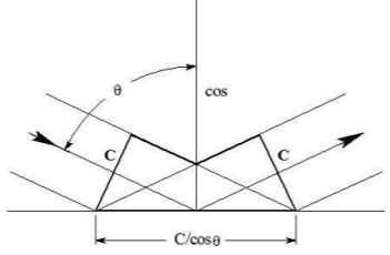
Fig. Geometry of energy flow for total internal reflection.
Metals have a high reflectivity, allowing them to reflect nearly all wavelengths in the visible spectrum. This is because to their high damping constant, which causes the light to travel a limited distance. Furthermore, some metals have a low refractive index, and when light passes through a medium with a higher refractive index to a media with a lower refractive index, the refracted ray will have a big deflection in regard to the normal, according to Snell's Law. This property explains how various metals, such as silver, gold, and copper, react to electromagnetic radiation. A schematic representation of this process is shown in Figure.
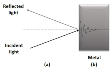
Figure: Reflectance phenomena where the incidence of light in metal leads to metallic reflection (a) and light attenuation or absorption (b).
Therefore, the Reflectance (R) of a material can be defined as the efficiency of a material to reflect incident light. This value depends only on the complex refractive index (n) and the damping constant (k), which is shown in Equation below.

The study of metallic reflectance can be applied to metallic coatings, which are expected to reflect light over a wide wavelength range. It can also explain the hues that metals exhibit. When white light is focused on silver, for example, it has a high reflectance over the visible spectrum, making it colourless. When irradiated with white light, gold, on the other hand, absorbs the blue and violet parts of the spectrum, resulting in a yellow colour. Figure shows the reflectance spectra of silver, gold, copper, and aluminium, which show that these metals exhibit high reflectance throughout a wide range of wavelengths, particularly in the visual range. However, if the frequency is large (lower wavelength values), silver, copper and gold have a drop in reflectance.
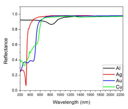
Figure: Reflectance spectra of the metals: aluminum (black line), silver (red line), gold (blue line) and copper (green line).
References:
1. Classical Electrodynamics by J.D. Jackson (Willey)-2007
2. Foundation of electromagnetic theory: Ritz and Milford (Pearson)-2008
3. Electricity and Magnetism: D C Tayal (Himalaya Publication)-2014
4. Optics: A.K.Ghatak (McGraw Hill Education)- 2017
5. Electricity and Magnetism: Chattopadhyaya, Rakhit (New Central)-2018