Unit 4
ELECTRICAL MEASURING INSTRUMENTS:
ELECTRICAL MEASURING INSTRUMENTS:
The instruments which use the permanent magnet for creating the stationary magnetic field between which the coil moves is known as the permanent magnet moving coil or PMMC instrument.
It operates on the principle that the torque is exerted on the moving coil placed in the field of the permanent magnet. The PMMC instrument gives the accurate result for DC measurement.
Construction:
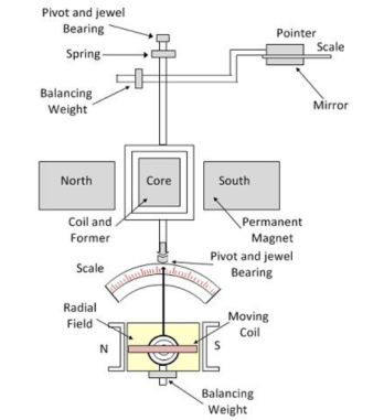
The moving coil and permanent magnet are the main part of the PMMC instrument.
Moving Coil – The coil is the current carrying part of the instruments which is freely moved between the stationary field of the permanent magnet. The current passes through the coil deflects it due to which the magnitude of the current or voltage is determined. The coil is mounted on the rectangular former which is made up of aluminium. The former increases the radial and uniform magnetic field between the air gap of the poles. The coil is wound with the silk cover copper wire between the poles of a magnet.
The coil is mounted on the rectangular former which is made up of aluminium. The former increases the radial and uniform magnetic field between the air gap of the poles. The coil is wound with the silk cover copper wire between the poles of a magnet.
Magnet System – The PMMC instrument using the permanent magnet for creating the stationary magnets. The Alcomax and Alnico material are used for creating the permanent magnet because this magnet has the high coercive force (The coercive force changes the magnetisation property of the magnet). Also, the magnet has high field intensities.
Control – In PMMC instrument the controlling torque is because of the springs. The springs are made up of phosphorous bronze and placed between the two jewel bearings. The spring also provides the path to the lead current to flow in and out of the moving coil. The controlling torque is mainly because of the suspension of the ribbon.
Damping – The damping torque is used for keeping the movement of the coil in rest. This damping torque is induced because of the movement of the aluminium core which is moving between the poles of the permanent magnet.
Pointer & Scale – The pointer is linked with the moving coil. The pointer notices the deflection of the coil, and the magnitude of their deviation is shown on the scale. The pointer is made of the lightweight material, and hence it is easily deflected with the movement of the coil. Sometimes the parallax error occurs in the instrument which is easily reduced by correctly aligning the blade of the pointer.
Torque Equation for PMMC Instrument
The deflecting torque induces because of the movement of the coil. The deflecting torque is expressed by the equation shown below.
Td = NBLdI ----------------------(1)
Where, N – Number of turns of coil
B – flux density in the air gap
L, d – the vertical and horizontal length of the side.
I – current through the coil.
G = NBLd ----------------------(2)
The spring provides the restoring torque to the moving coil which is expressed as Tc = KƟ ---------------------(3)
Where K = Spring constant.
For final deflection, Tc = Td By substituting the value of equation (1) and (3) we get,
K Ɵ = G I
Ɵ = GI/K -------------------------------(4)
I = K/G Ɵ --------------------------------(5)
The above equation shows that the deflection torque is directly proportional to the current passing through the coil.
Problem:
A PMMC instrument gives full scale reading of 25mA when a potential difference across its terminals is 75mV. Show how it can be used
(a) As as ammeter for the range of 0-100 A
(b) As a voltmeter for the range of 0-750V. Also find the multiplying factor of shunt and voltage amplification.
Instrument resistance Rm = Potential drop across terminals / Instrument current
= 75 x 10-3 / 25 x 10 -3 = 3Ω
Current to be measured I = 100 A
Multiplying power of shunt m = I/Im = 100/ 25 x 10 -3 = 4000
Shunt resistance for full scale deflection at 100A .
Rsh = Rm / m-1 = 3/ 4000 -1 = 3/3999= 7.5 x 10 -4 =0.75mA
(b)Voltage to be measured V = 750V
Rse = V/Im – Rm = 750 / 25 x 10 -3 -3 = 29,997Ω
Voltage amplification = 750 / 75 x 10 -3 = 10,000 Ans
Shunts are used for the extension of range of Ammeters. So a good shunt should have the following properties:-
1- The temperature coefficient of shunt should be low
2- Resistance of shunt should not vary with time
3- They should carry current without excessive temperature rise
4- They should have thermal electromotive force with copper * ‘Manganin’ is used for DC shunt and ‘Constantan’ as AC shunt.
A Multiplier is an active element that amplifies a voltage or current to enable a less sensitive device or circuit to make use of it.
A multiplier is a high-value resistance connected in series with a current meter, to enable it to read and be calibrated in terms of voltage.
Moving-iron instruments are generally used to measure alternating voltages and currents. In moving-iron instruments the movable system consists of one or more pieces of specially shaped soft iron, which are so pivoted as to be acted upon by the magnetic field produced by the current in coil.
There are two general types of moving-iron instruments namely:
Repulsion (or double iron) type (figure 1)
Attraction (or single-iron) type (figure 2)
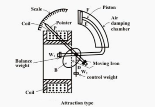
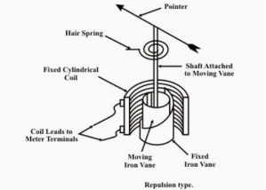
Figure 2 Figure1
The brief description of different components of a moving-iron instrument is given below:
Moving element: a small piece of soft iron in the form of a vane or rod.
Coil: to produce the magnetic field due to current flowing through it and also to magnetize the iron pieces.
In repulsion type, a fixed vane or rod is also used and magnetized with the same polarity.
Control torque is provided by spring or weight (gravity).
Damping torque is normally pneumatic, the damping device consisting of an air chamber and a moving vane attached to the instrument spindle.
Deflecting torque produces a movement on an aluminum pointer over a graduated scale.
The deflecting torque in any moving-iron instrument is due to forces on a small piece of magnetically ‘soft’ iron that is magnetized by a coil carrying the operating current. In repulsion type moving–iron instrument consists of two cylindrical soft iron vanes mounted within a fixed current-carrying coil.
One iron vane is held fixed to the coil frame and other is free to rotate, carrying with it the pointer shaft. Two irons lie in the magnetic field produced by the coil that consists of only few turns if the instrument is an ammeter or of many turns if the instrument is a voltmeter.
Current in the coil induces both vanes to become magnetized and repulsion between the similarly magnetized vanes produces a proportional rotation
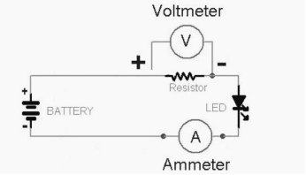
Ammeter
Instrument used to measure current in the circuit.
Always connected in series with the circuit and carries the current to be measured.
This current flowing through the coil produces the desired deflecting torque.
It should have low resistance as it is to be connected in series.
Voltmeter
Instrument used to measure voltage between two points in a circuit.
Always connected in parallel.
Current flowing through the operating coil of the meter produces deflecting torque.
It should have high resistance. Thus, a high resistance of order of kilo ohms is connected in series with the
Coil of the instrument.
Ranges of Ammeter and Voltmeter
For a given moving-iron instrument the ampere-turns necessary to produce full-scale deflection are constant.
One can alter the range of ammeters by providing a shunt coil with the moving coil.
Voltmeter range may be altered connecting a resistance in series with the coil. Hence the same coil winding
Specification may be employed for a number of ranges.
Dynamometer type wattmeter works on very simple principle and this principle can be stated as when any current carrying conductor is placed inside a magnetic field, it experiences a mechanical force and due to this mechanical force deflection of conductor takes place.
There are two types of coils present in the electrodynamometer. They are :
Moving Coil
Moving coil moves the pointer with the help of spring control instrument. Limited of current flows through the moving coil to avoid heating. So, in order to limit the current, we have connected the high value resistor in series with the moving coil.
The moving is air cored and is mounted on a pivoted spindle and can move freely. In electrodynamometer type wattmeter, moving coil works as pressure coil. Hence moving coil is connected across the voltage and thus the current flowing through this coil is always proportional to the voltage.
Fixed Coil
The fixed coil is divided into two equal parts and these are connected in series with the load, therefore the load current will flow through these coils. The reason is very obvious of using two fixed coils instead of one, so that it can be constructed to carry considerable amount of electric current. These coils are called the current coils of electrodynamometer type wattmeter.
To derive the expressions for the controlling torque and deflecting torques. In order to derive these expressions let us consider the circuit diagram given below:
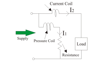
The instantaneous torque in electrodynamic type instruments is directly proportional to the product of instantaneous values of currents flowing through both the coils and the rate of change of flux linked with the circuit.
Let I1 and I2 be the instantaneous values of currents in pressure and current coils respectively. So the expression for the torque can be written as:
T = I1 x I2 x dM/dx
Where, x is the angle.
Now let the applied value of voltage across the pressure coil be
v =  V sinwt
Assuming the electrical resistance to the pressure coil be very high hence we can neglect reactance with respect to its resistance. In this the impedance is equal to its electrical resistance therefore it is purely resistive.
The expression for instantaneous current can be written as I2 = v / Rp where Rp is the resistance of pressure coil.
I 2 =  x V sin wt / Rp
If there is phase difference between voltage and electric current, then expression for instantaneous current through current coil can be written as
I1 = I(t) =  I sin(wt - ɸ)
As current through the pressure coil is very very small compared to the current through current coil hence current through the current coil can be considered as equal to total load current.
Hence the instantaneous value of torque can be written as
 x V sin wt/ Rp x
  x I x sin(wt - ɸ) x dM/dx
Average value of deflecting torque can be obtained by integrating the instantaneous torque from limit 0 to T, where T is the time period of the cycle.
Td = deflecting torque = VI/Rp cos ɸ x dM/dx
Controlling torque is given by Tc = Kx where K is spring constant and x is final steady state value of deflection.
Single phase induction type energy meter is extensively used to measure energy supplied to a single phase circuit.
Operating principle of Single-phase induction type energy meter:
The operation of induction type energy meter depends on the passage of alternating current through two suitably located coils producing rotating magnetic field which interacts with a metallic disc suspended near to the coils and cause the disc to rotate.
The current coil carries the line current and produces field in phase with the line current. The pressure coil is made highly inductive so that the current through it lags behind the supply voltage by 90 degrees. Thus, a phase difference of 90 degrees exists between the fluxes produced by the two coils. This sets up rotating field which interacts with the disc to cause it to rotate.
Construction of Single phase induction type energy meter:
A single phase induction type energy meter generally has:
1. Moving system
2. Operating mechanism
3. Recording mechanism
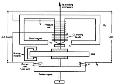 |
Single phase induction type energy meter diagram |
1. Moving system: The moving system consists of a light aluminium disc mounted on a vertical spindle. The spindle is supported by up-shaped jewelled bearings at the bottom end and has a spring journal bearing at the top end.
There is no pointer and control spring so that the disc makes continuous rotation under the action of deflecting torque.
2. Operating mechanism: It consists of series magnet, shunt magnet and breaking magnet.
Series magnet: The series magnet consists of a number of U-shaped laminations assembled together to form a core. A thick wire of few turns is wound on both legs of the U-shaped laminated core. The wound coil is known as current coil and is connected in series with the load so that it carries the load current. The series magnet is placed underside the aluminium disc and produces magnetic field proportional to and in phase with the current.
Shunt Magnet: The shunt magnet consists of a number of M-shaped laminations assembled together to form a core. A fine wire of large turns is wound on the central limb of this magnet.
The wound coil is known as pressure coil and is connected across the load so that it carries current proportional to supply voltage. The shunt magnet is placed above the aluminium disc as shown.
In order to obtain deflecting torque, current in the pressure coil must lag behind the supply voltage by 90 degrees. This necessary phase shift is obtained by placing a copper ring over central limb of shunt magnet.
This copper ring acts as a short- circuited transformer secondary. As its inductance is high as compared with its resistance, the current circulating in the ring will lag by nearly 90 degrees behind the voltage producing it.
Braking magnet: The speed of aluminium disc is controlled to the required value by the C-shaped permanent braking magnet. The magnet is mounted so that the disc revolves in the air gap between the polar extremities.
As the disc rotates, currents are induced in the disc because it cuts the flux produced by the breaking magnet. The direction of the current in the disc is such that it opposes the rotation of the disc.
Since the induced currents in the disc are proportional to the speed of the disc, therefore, breaking torque is proportional to the disc speed.
3. Recording mechanism: The number of revolutions of the disc s a measure of the electrical energy passing through the meter and is recorded on dials which are geared to the shaft.
Working:
When the energy meter is connected in the circuit to measure electrical energy, the current coil carries the load current whereas the pressure coil carries current proportional to the supply voltage.
The magnetic field due to current coil is in phase with line current whereas the magnetic field produced due to pressure coil lags approximately 90 degrees behind the supply voltage.
The current coil field produces eddy currents in the disc which reacts with the field due to the pressure coil. Thus, a driving force is created which causes the disc to rotate.
The braking magnet provides the braking torque on the disc. By altering the position of this magnet, desired speed can be obtained. The spindle is geared to the recording mechanism so that electrical energy consumed in the circuit is directly registered in kWh.
POWER SUPPLY SYSTEMS:
In a thermal power plant, heat produced by burning coal is used to boil water to form steam. The steam, at high temperature and pressure, rotates the turbine and its shaft, which drives the generator to produce electricity.
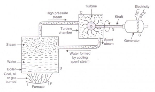
Chemical energy stored in coal after a couple of transformations produces electrical energy at the generator terminals as depicted in the figure. Thus, proximity of a generating station nearer to a coal reserve and water sources will be most economical as the cost of transporting coal gets reduced. In our country coal is available in abundance and naturally thermal power plants are most popular. However, these plants pollute the atmosphere because of burning of coals.
A large amount of ash is produced every day in a thermal plant and effective handling of the ash adds to the running cost of the plant. Nonetheless 57% of the generation in out country is from thermal plants. The speed of alternator used in thermal plants is 3000 rpm which means 2-pole alternators are used in such plants.
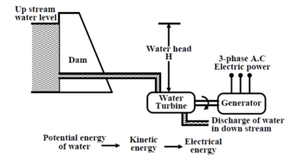
In a hydel power station, water head is used to drive water turbine coupled to the generator. Water head may be available in hilly region naturally in the form of water reservoir (lakes etc.) at the hill tops. The potential energy of water can be used to drive the turbo generator set installed at the base of the hills through piping called pen stock. Water head may also be created artificially by constructing dams on a suitable river. In contrast to a thermal plant, hydel power plants are eco-friendly, neat and clean as no fuel is to be burnt to produce electricity. While running cost of such plants are low, the initial installation cost is rather high compared to a thermal plants due to massive civil construction necessary. Also sites to be selected for such plants depend upon natural availability of water reservoirs at hill tops or availability of suitable rivers for constructing dams. Water turbines generally operate at low rpm, so number of poles of the alternator are high. For example a 20-pole alternator the rpm of the turbine is only 300 rpm.
Nuclear:
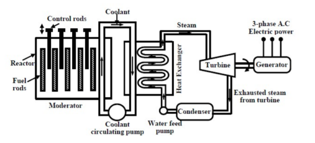
As coal reserve is not unlimited, there is natural threat to thermal power plants based on coal. It is estimated that within next 30 to 40 years, coal reserve will exhaust if it is consumed at the present rate. Nuclear power plants are thought to be the solution for bulk power generation. At present the installed capacity of nuclear power plant is about 4300 MW and expected to expand further in our 235 country. The present- day atomic power plants work on the principle of nuclear fission of 235 U. In the 238 natural uranium, U constitutes only 0.72% and remaining parts is constituted by 99.27% of U and only about 0.05% of 234 U. The concentration of 235 U may be increased to 90% by gas diffusion process to obtain enriched 235 U. When 235 U is bombarded by neutrons a lot of heat energy along with 235 additional neutrons are produced. These new neutrons further bombard U producing more heat and more neutrons. Thus, a chain reaction sets up. However, this reaction is allowed to take place in a controlled manner inside a closed chamber called nuclear reactor. To ensure sustainable chain reaction, moderator and control rods are used. Moderators such as heavy water (deuterium) or very 12 pure carbon C are used to reduce the speed of neutrons. To control the number neutrons, control rods made of cadmium or boron steel are inserted inside the reactor. The control rods can absorb neutrons. If we want to decrease the number neutrons, the control rods are lowered down further and vice versa. The heat generated inside the reactor is taken out of the chamber with the help of a coolant such as liquid sodium or some gaseous fluids. The coolant gives up the heat to water in heat exchanger to convert it to steam as shown in figure . The steam then drives the turbo set and the exhaust steam from the turbine is cooled and fed back to the heat exchanger with the help of water feed pump. Calculation shows that to produce 1000 MW of electrical power in coal based thermal 6 plant, about 6 × 10 235 Kg of coal is to be burnt daily while for the same amount of power, only about 2.5 Kg of U is to be used per day in a nuclear power stations.
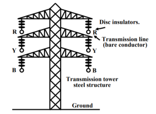
Transmission of power The huge amount of power generated in a power station (hundreds of MW) is to be transported over a long distance (hundreds of kilometers) to load centers to cater power to consumers with the help of transmission line and transmission towers as shown in figure
Let us consider a generating station producing 120 MW power and we want to transmit it over a large distance. Let the voltage generated (line to line) at the alternator be 10 kV. Then to transmit 120 MW of power at 10 kV, current in the transmission line can be easily calculated by using power formula for 3-phases follows:
I = P /  VL cos Ɵ
= 120 x 10 6 / x 10 x 10 3 x 0.8 = 8660A
Instead of choosing 10 kV transmission voltage, if transmission voltage were chosen to be 400 kV, current value in the line would have been only 261.5 A. So sectional area of the transmission line (copper conductor) will now be much smaller compared to 10 kV transmission voltage. In other words, the cost of conductor will be greatly reduced if power is transmitted at higher and higher transmission voltage. The use of higher voltage (hence lower current in the line) reduces voltage drop in the line resistance and reactance. Also, transmission losses is reduced.
Distribution:
The loads of a big city are primarily residential complexes, offices, schools, hotels, street lighting etc. These types of consumers are called LT (low tension) consumers. Apart from this there may be medium and small scale industries located in the outskirts of the city. LT consumers are to be supplied with single phase, 220 V, 40 Hz.

Power receive at a 33 kV substation is first stepped down to 6 kV and with the help of under- ground cables (called feeder lines), power flow is directed to different directions of the city. At the last level, step down transformers are used to step down the voltage form 6 kV to 400 V. These transformers are called distribution transformers with 400 V, star connected secondary.
Notice that such transformers mounted on poles in cities beside the roads. These are called pole mounted substations.
From the secondary of these transformers 4 terminals (R, Y, B and N) come out. N is called the neutral and taken out from the common point of star connected secondary. Voltage between any two phases (i.e., R-Y, Y-B and B-R) is 400 V and between any phase and neutral is 230 V(= 400 3).
Residential buildings are supplied with single phase 230V, 50Hz. So individual are to be supplied with any one of the phases and neutral. Supply authority tries to see that the loads remain evenly balanced among the phases as far as possible.
Which means roughly one third of the consumers will be supplied from R-N, next one third from Y-N and the remaining one third from B-N.
The distribution of power from the pole mounted substation can be done either by (1) overhead lines (bare conductors) or by (2) underground cables. Use of overhead lines although cheap, is often accident prone and also theft of power by hooking from the lines take place. Although costly, in big cities and thickly populated areas underground cables for distribution of power, are used.
Electric heating is extensively used both for domestic and industrial applications. Domestic applications include (i) room heaters (ii) immersion heaters for water heating (iii) hot plates for cooking (iv) electric kettles (v) electric irons (vi) pop-corn plants (vii) electric ovens for bakeries and (viii) electric toasters etc.Industrial applications of electric heating include (i) melting of metals (ii) heat treatment of metals like annealing, tempering, soldering and brazing etc. (iii) moulding of glass (iv) baking of insulators (v) enameling of copper wires etc.
Welding
It is also called inert-gas consumable- electrode process. The fusible wire electrode is driven by the drive wheels. Its function is two-fold: to produce arc column and to provide filler material. This process uses inert gas for shielding the weld zone from atmospheric contamination. Argon is used to weld non-ferrous metals though helium gives better control of porosity and arc stability. This process can deposit large quantities of weld metal at a fast welding speed. The process is easily adaptable to semi-automatic or fully automatic operations. (b) Welding Equipment
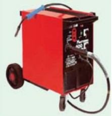
The basic MIG welding system consists of the following :
1. Welding power supply
2. Inert gas supply with a regulator and flow meter
3. Wire feed unit containing controls for wire feed, gas flow and the ON/OFF switch for MIG torch
4. MIG torch
5. Depending on amperage, a water cooling unit.
References:
An Integrated Course In Electrical Engineering (3rd Edition) Book by J. B. Gupta
Basic Electrical Engineering Book by I.J. Nagrath
Objective Electrical Technology Book by Rohit Mehta and V.K. Mehta