Series R-L Circuit
|
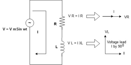
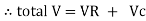
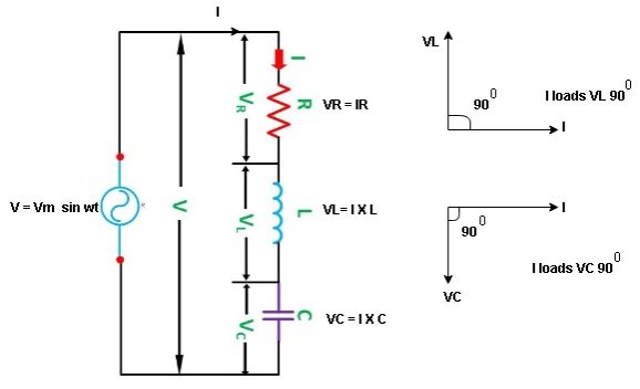
Consider a series R-L circuit connected across voltage source V= Vm sin wt Like some, I is the current flowing through the resistor and inductor due do this current-voltage drops across R and L R
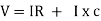
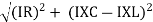
V = IR + I X L |
|


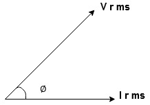
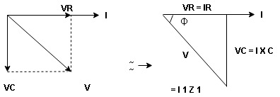
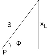
Take current as the reference phasor: 1) for resistor current is in phase with voltage 2) for Inductor voltage leads current or current lags voltage by 90 0.
|
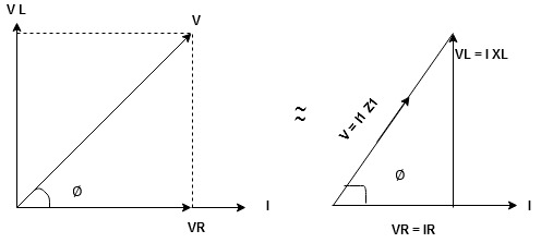
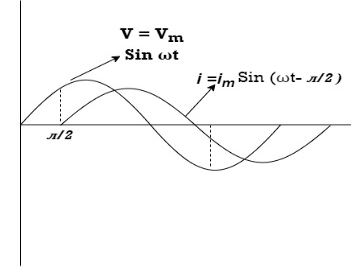
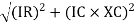
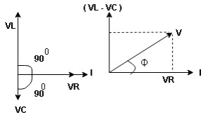
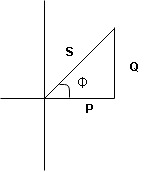
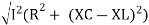
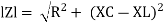
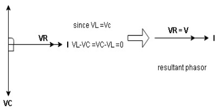
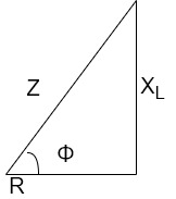
For voltage triangle Ø is the power factor angle between current and resultant voltage V and V =
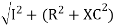
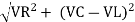
V =
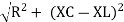
where Z = Impedance of circuit and its value is |

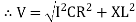


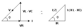
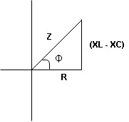
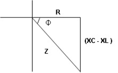
Impedance Triangle
Divide voltage triangle by I
|
Rectangular form of Z = R+ixL and polar from of Z = (+ j X L + Where |
|


Current Equation:
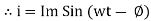
From the voltage triangle, we can sec. that voltage is leading current by Or i =
|


Resultant Phasor Diagram form Voltage and current eqth.
|
Waveform
|
Power equation P = V .I. P = Vm Sin wt Im Sin wt – Ø P = Vm Im (Sin wt) Sin (wt – Ø) | |
P = Since 2 sin A Sin B = Cos (A-B) – Cos (A+B) P =
| |


①② Average Power pang = Since ② term becomes zero because Integration of cosine come from 0 to 2ƛ
|


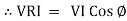
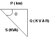
Power Triangle:
|
From VI = VRI + VLI B Now cos Ø in
Similarly Sin
Apparent Power Average or true Reactive or useless power Or real or active -Unit (VI) Unit (Watts) C/W (VAR) denoted by (Ø) Denoted by [S] denoted by [P] |


Power  for R L ekt.
|
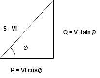
Series R-C circuit
|
V = Vm sin wt
VR

 I
I
|
- Consider a series R – C circuit in which resistor R is connected in series with capacitor C across an ac voltage so use V = VM Sin wt (voltage equation).
R and C R and C And C
|
|


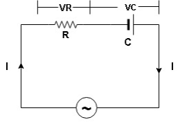
Voltage triangle: take current as the reference phasor 1) for resistor current is in phase with voltage 2) for capacitor current leads voltage or voltage lags behind current by 900
|
Where Ø is the power factor angle between current and voltage (resultant) V And from voltage V = V = V = V = Where Z = impedance of the circuit and its value is lZl =
|


Impendence triangle:
Divide voltage  by
by  as shown
|
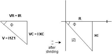
The rectangular form of Z = R - jXc The polar form of Z = lZl L - Ø ( - Ø and –jXc because it is in the fourth quadrant ) where lZl = and Ø = tan -1 | |
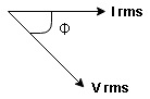
Current equation : from voltage triangle we can see that voltage is lagging current by Ø or current is leading voltage by Ø
Or i =
| |


Resultant phasor diagram from voltage and current equation
|
Resultant waveform:
|
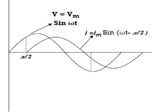
Power Equation : P = V. I P = Vm sin wt. Im Sin (wt + Ø) = Vm Im sin wt sin (wt + Ø) 2 Sin A Sin B = Cos (A-B) – Cos (A+B)
|


Average power
pang =  Cos Ø
Cos Ø
since 2 terms integration of cosine wave from 0 to 2ƛ become zero
 2 terms become zero
 pang = Vrms Irms Cos Ø
Power triangle RC Circuit:
|
R-L-C series circuit
|
Consider ac voltage source V = Vm sin wt connected across the combination of R L and C. when I flowing in the circuit voltage drops across each component as shown below.
VR = IR, VL = I  L, VC = I
  C
C
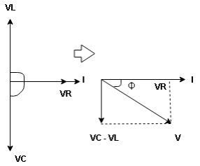
① XL> XC, ② XC> XL, ③ XL = XC ① XL > XC: Since we have assumed XL> XC
|


|
VL and VC are 180 0 out of phase.
Therefore cancel out each other
 Resultant voltage triangle
|
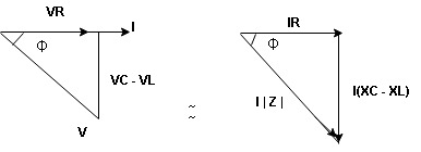
Now V = VR + VL + VC From voltage triangle V =
|


Impendence  : divide voltage
|
Rectangular form Z = R + j (XL – XC) Polor form Z = Where |
And Ø = tan-1 |


i = i = as VL
|
|


|
- XC
 XL :Since we have assured XC
  XL
XL
 the voltage drops across XC
  than XL
 XC
XC  XL (A)
 voltage triangle considering condition (A)
|
 Resultant Voltage
|
Now V = VR + VL + VC From voltage V = V =
|


 Impedance
  : Divide voltage
|
Polar form : Z = Where And Ø = tan-1 –
as VC since i = |
|


- Power
 :
:
|
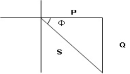
- XL= XC (resonance condition):
ɡȴ XL= XC then VL= VC and they are 1800 out of phase with each other  they will cancel out each other and their resultant will have zero value.
Hence resultant V = VR and it will be in phase with I as shown in the below phasor diagram.
|
From the above resultant phasor diagram
V =VR + IR Or V = I |

Because lZl + R
Thus Impedance Z is purely resistive for XL = XC and circuit current will be in phase with source voltage.

 Since VR=V Øis zero when XL = XC
  power is unity
ie pang = Vrms I rms cos Ø = 1 cos o = 1
maximum power will be transferred by the condition. XL = XC
- Apparent power: (S):- it is defined as product of rms value of voltage (v) and current (I), or it is the total power/maximum power
S= V × I
Unit - Volte- Ampere (VA)
In kilo – KVA
2. Real power/ True power/Active power/Useful power: (P) it is defined as the product of rms value of voltage and current and the active component or it is the average or actual power consumed by the resistive path (R) in the given combinational circuit.
It is measured in watts
P = VI  Φ watts / KW, where Φ is the power factor angle.
3. Reactive power/Imaginary/useless power [Q]
It is defined as the product of voltage, current and sine B and I
Therefore,
Q= V.I  Φ
Φ
Unit –VA R
In kilo- KVAR
|
As we know power factor is cosine of angle between voltage and current
i.e. Φ.F= CosΦ |
In other words, also we can derive it from impedance triangle
Now consider Impedance triangle in R.L.ckt
|
From triangle , Now Power factor = |


Resonance with Definition, condition and derivation
Resonance in series RLC circuit
Definition:
It is defined as the phenomenon which takes place in the series or parallel R-L-C circuit which leads to unity power factor
Voltage and current in R-L-C ckt are in phase with each other.
Resonance is used in many communication circuits such as radio receiver.
Resonance in series RLC -> series resonance in parallel->antiresonance/parallel resonance
Condition for resonance
XL=XC
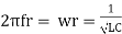
Resonant frequency (fr): For given values R-L-C the inductive reactance XL becomes exactly equal to the capacitive reactance XC only at one particular frequency. This frequency is called as resonant frequency and denoted by ( fr)
Expression for resonant frequency (fr)
We know that XL =
At a particle or frequency f=fr,the inductive and capacitive reactance are exactly equal Therefore, XL = XC ----at f=fr i.e. Therefore,
and |


Advantages of 3 phase power circuit:
(1) Three phase power is constant power i.e. it doesn't vary with time. On the other hand, single phase power fluctuates periodically. For this reason, three phase machines give less vibration and noise as compared to single phase ones.
(2) If three phase currents are balanced, they cancel out and no return path is required. Likewise, if three phase fluxes are balanced in a magnetic core, they cancel out and hence no return limb is required. Therefore, for the same power output, three phase machine is smaller and cheaper as compared to single phase machine.
For the same reason, it will be cheaper to transmit power by a three phase line as compared to single phase line for the same amount of power to be delivered.
(3) Three phase currents in a rotating machine produce revolving magnetic field. This led to development of three phase induction motor, one of the most robust and cheapest motor. In fact, this was the main reason for adopting three phase supply in preference to single phase supply.
3 phase power circuit:
3Φ system in which three voltages are of identical magnitudes and frequency and are displaced by 120° from each other called as symmetrical system.
Phase sequence:
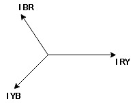
The sequence in which the three phases reach their maximum positive values. Sequence is R-Y-B. Three colours used to denote three faces are red, yellow and blue.
The direction of rotation of 3Φ machines depends on phase sequence. If a sequence is changed i.e. R-B-Y then the direction of rotation will be reversed.
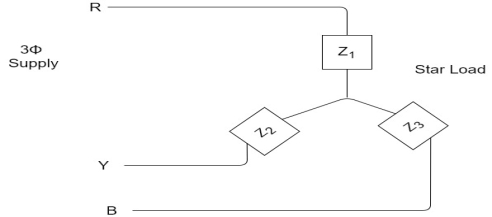
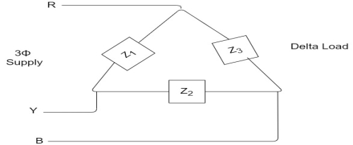
Types of loads
- Star connection of load
- Delta connection of load
|
|
Balanced load:
Balanced load is that in which magnitudes of all impedances connected in the load are are equal and the phase angles of them are also equal.
i.e. If. |


Phasor Diagram
Consider equation ①
Note: we are getting resultant line current IR by subtracting 2 phase currents IRY and IBR  take phase currents at reference as shown
|
|
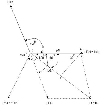
Cos 300 =
|


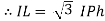
- Complete phases diagram for delta connected balanced Inductive load.
|
Phase current IYB lags behind VYB which is phase voltage as the load is inductive
Measurement of three phase power by two wattmeter method:
In two wattmeter method, a three phase balanced voltage is to a balanced three phase load where the current in each phase is assumed lagging by an angle of Ø behind the corresponding phase voltage.
The schematic diagram for the measurement of three phase power using two wattmeter method is shown below.
|
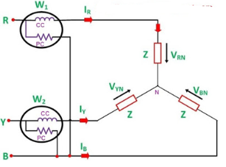
From the figure, it is obvious that current through the Current Coil (CC) of Wattmeter W1 = IR, current though Current Coil of wattmeter W2 = IB whereas the potential difference seen by the Pressure Coil (PC) of wattmeter W1= VRB (Line Voltage) and potential difference seen by Pressure Coil of wattmeter W2 = VBY. The phasor diagram of the above circuit is drawn by taking VR as reference phasor as shown below.
|
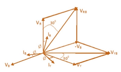
From the above phasor diagram,
Angle between the current IRand voltage VRB = (30° – Ø)
Angle between current IYand voltage VYB = (30° + Ø)
Therefore, Active power measured by wattmeter W1 = VRBIR Cos (30° – Ø)
Similarly, Active power measured by wattmeter W2 = VYBIYCos(30° + Ø)
As the load is balanced, therefore magnitude of line voltage will be same irrespective of phase taken i.e. VRY, VYB and VRB all will have same magnitude. Also for Star / Y connection line current and phase current are equal, say IR = IY = Let VRY = VYB = VRB = VL Therefore, W1 = VRBIRCos (30° – Ø) = VLICos(30° – Ø) In the same manner, | ||
IB = I W2 = VLICos(30° + Ø) Hence, total power measured by wattmeter for the balanced three phase load is given as, W = W1 + W2 = VLI×Cos(30° – Ø) + VLI×Cos(30° + Ø) = VLI [Cos(30° – Ø) + Cos(30° + Ø)] = 2VLI×Cos30°CosØ ……………….[ CosC + CosD = 2Cos(C+D)/2×Cos(C-D)/2 ] =√3VLICosØ Therefore, total power measured by wattmeter W = √3VLICosØ Now, suppose you are asked to find the power factor of the load when individual power measured by the wattmeter are given, then we should proceed as W1 + W2 = √3VLICosØ ……………………………..(1) Similarly, W1 – W2= VLI×Cos(30° – Ø) + VLI×Cos(30° + Ø) = VLI [Cos(30° – Ø) + Cos(30° + Ø)] = 2VLI×Sin30°SinØ ………[ CosC – CosD = 2Sin(C+D)/2×Sin(D-C)/2 ] = VLISinØ Hence, W1 – W2 = VLISinØ ………………………………(2) Dividing equation (2) by equation (1), (W1 – W2) / (W1 + W2) = VLISinØ / √3VLICosØ (W1 – W2) / (W1 + W2) = (tanØ) /√3 Hence, | ||
tanØ = √3[(W1 – W2) / (W1 + W2)] | ||
From the above equation, we can find the value of Ø and hence the power factor Cos Ø of the load.
Hope you understand the method of measurement of three phase power using two wattmeter method. Now we will consider three cases and will observe the how the individual wattmeter measures the power in each case.
Case1: When the power factor of load is unity. As the power factor of load is unity, hence Ø = 0 Therefore, Power measured by first wattmeter W1= VLI Cos(30° – 0) = VLI Cos30° = 0.866 VLI Power measured by second wattmeter W2= VLI Cos(30° + 0) = VLI Cos30° = 0.866 VLI |
Thus we see that, when the power factor of load is unity then both the wattmeter reads the same value.
Case2: When power factor of load is 0.5 lagging.
As power factor is 0.5 hence CosØ = 0.5 i.e. Ø = 60°
Therefore, Power measured by first wattmeter W1= VLI Cos (30° – 60°) = VLI Cos30° ……[Cos (-Ɵ) = CosƟ ] = 0.866 VLI Power measured by second wattmeter W2= VLI Cos(30° + 60°) = VLI Cos90° = 0 |
Thus we see that, when power factor of load is 0.5 lagging then power is only measured by first wattmeter and reading of second wattmeter is ZERO.
Case3: When power factor of load is zero. As power factor of load is zero, hence CosØ = 0 i.e. Ø = 90° Therefore, Power measured by first wattmeter W1= VLI Cos(30° – 90°) = VLI Cos60° = 0.5 VLI Power measured by second wattmeter W2= VLI Cos(30° + 90°) = –VLI Cos60° = -0.5 VLI |
Thus we see that, when power factor of load is zero then one wattmeter reads +ive while second wattmeter reads –ive. As second wattmeter reads –ive hence wattmeter won’t read anything practically, therefore for second wattmeter we need to interchange the leads of either Pressure Coil or Current Coil so that second wattmeter may read value. As we have interchanged the connection of leads of either PC or CC, hence second wattmeter will read +ive but while calculating the total power measured we must take the reading of second wattmeter as –ive.
It shall be noted that when 60° <Ø < 90°, reading of one wattmeter will be positive while the reading of second wattmeter will be negative.


