Construction details of D.C. Machine
Whether machine is D.C. generator or motor the construction basically remains the same.
|
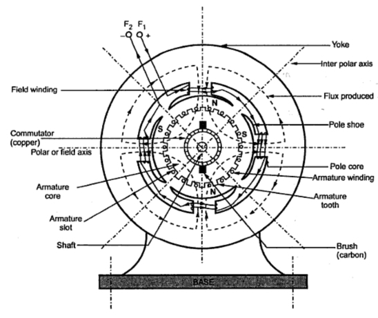
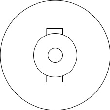
A cross section of typical D.C. machine
1)Yoke
a) Functions
1. It serve the purpose of outermost cover of the D.C. machine. So that the insulating materials get protected from harmful atmospheric elements like moisture. Dust and various gases like  , acidic fumes etc.
2. It provides mechanical support to the poles.
3. It forms a part of the magnetic circuit.
It provides a path of low reluctance for magnetic flux. The low reluctance path is important to avoid wastage of power to provide same flux large current and hence the power is necessary if the path has high reluctance to produce the same flux.
4.Choice of material: - It is prepared by using cast iron, silicon steel is used which provides high permeability i.e. low reluctance and gives good mechanical strength.
2) Poles
|
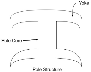
Pole structure
Each Pole is divided into two parts namely
- Pol core
- Pole shoe
Functions of pole core and pole shoe: -
- Pole core basically carries a field winding which is necessary to produce the flux.
- It directs the flux produced through air gap to armature core to the next pole.
- Pole shoe enlarge the area of armature core to come across the flux, which is necessary to produce larger induced e.m.f. To achieve this, sports shoe has been given a particular shape.
Choice of material: -
It is made up of magnetic material like cast iron or cast steel.
As it requires a definite shape and size, laminated construction is used. The laminations of required size and shape are stamped together to get a pole which is then bolted to the yoke.
3) Field Winding (
The field winding is wound on the pole core with a definite direction.
a) Functions: -
To carry current due to which pole core on which the field winding is placed behaves as an electromagnet, producing necessary flux.
As it helps in producing the magnetic field i.e. exciting the poles as an electromagnet it is called Field winding or Exciting winding.
b) Choice of material: -
It has to carry current hence obviously made up of some conducting material.
So aluminium or copper is the choice. But field coils are required to take four types of shape and bent about pole core and copper has good pliability i.e. it can be bend easily. So copper is the proper choice. field winding is divided into various coils called field coils. These are connected in series with each other and wound in such direction around pole cores, such that alternate 'N' and 'S' poles are formed.
The total number of poles is denoted as P.
4) Armature
The armature is further divided into two parts namely
- Armature core
- Armature winding
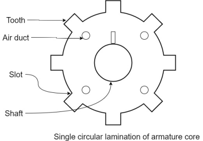
1.Armature core: - Armature core is cylindrical in in shape mounted on the shaft. It consists of slots on its periphery and air ducts to permit the air flow through armature which serves cooling purpose.
a) Functions-
1) Armature core provides house for armature winding i.e. armature conductors.
2)To provide the path of low reluctance to the magnetic flux produced by the field winding.
|
b) Choice of material: -
As it has to provide a low reluctance path to the flux, it is made up of magnetic material like cast iron or cast steel.
It is made up of laminated construction to keep Eddy current loss as low as possible. A single circular lamination used for the construction of armature core is shown in figure.
3. Armature winding
Armature winding is nothing but the interconnection of the armature conductors placed in the slots provided on the armature core periphery.
When the armature is rotated in case of generator magnetic flux gets cut by armature conductors and e.m.f gets induced in them.
a) Functions
1) curvatures of e.m.f takes place in the armature winding in case of generators.
2) To carry the current supplied in case of D.C. motors.
3) To do the useful work in the external circuit.
b) Choice of Material: -
As armature winding carries entire current which depends on external load, it has to be made up of conducting material which is copper.
5.Commutator
The basic nature of e.m.f in the armature conductors is alternating. This needs verification in case of D.C. generator, which is possible by a device called commutator.
a) Functions:
1)To facilitate the collection of current from the armature conductors.
2) To convert internally developed alternating e.m.f to unidirectional (D.C.) e.m.f.
3) To produce unidirectional torque in case of motors
b) Choice of Material: -
As it collects current from armature, it is also made up of copper segments.
|
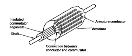
It is cylindrical in shape and is made up of wedge-shaped segments of hand drawn high conductivity copper. the segments are insulated from each other by thin layer of Mica.
Each commutator segment is connected to the armature conductor by means of copper lug or strip. This construction is shown in figure above.
6. Brushes and Brush Gear
Brushes are stationary and resting on the surface of the commutator.
a) Function-
to collect current from computer and make it available to stationary external circuit.
b) Choice of Material: -
Brushes are normally made up of soft material like carbon.
To avoid wear and tear of commentator the brushes are made up of soft material like carbon.
7) Bearings
Ball bearings are usually used as they are more reliable. For heavy duty machines roller bearing are preferred.
EMF equation of generator and torque equation of motor
|
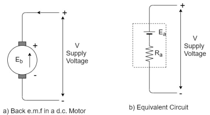
Back EMF in DC motor
- It is seen in the generating action that when a conductor cuts the line of flux EMF gets induced in the conductor. In a DC motor after a motoring action a major start rotating and armature conductor cut the main flux so is there a generating action existing in a motor after Moni following actions
- There is induced EMF in the rotating armature conductors according to Faraday’s law of electromagnetic induction this induced EMF in the armature always act in the opposite direction to the supply voltage.
- This is according to the Lenz’s law which states that the direction of the induced EMF is always so as to oppose the cause producing it.
- In a DC motor electrical input that is the supply voltage is the cause for the armature current and the motoring action and hence this induced EMF oppose the supply voltage this EMF tries to set up a current through our nature which is in the opposite direction to that which supply voltage is force in through the conductor.
|
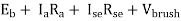
As this EMF always opposes the supply voltage it is called back EMF and denoted as  .Though it is denoted as
  basically it gets generated by the generating action which we have seen earlier in case of generators. So its magnitude can be determined by the EMF equation which is derived earlier.
|

Where all symbols carry the same meaning as seen earlier in case of generators
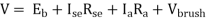
This EMF issued systematically in figure a so if v is supply voltage in volts & is the value of the armature resistance the equivalent electric circuit can be shown in figure b
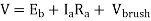
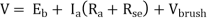
Voltage equation of DC motor
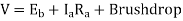
From the equivalent circuit the voltage equation for a DC motor can be obtained as
The brush drop is practically neglected. Hence the armature current
|


Significance of back EMF
Due to the presence of back EMF the DC motor becomes a regulating machine that is motor adjust itself to draw the armature current just enough to satisfy the load demand.
he basic principle of this fact is that the back EMF is proportional to speed 
When load is suddenly put on the motor. Motor tries to slow down. So speed of the motor reduces due to which back EMF also decreases. So the net voltage across the armature Increases and motor draws more armature current.
Due to the increased armature current force experienced by the conductors and hence the torque on the armature increases. The increase in the torque is just sufficient to satisfy increase load demand.
When load on the motor is decreased the speed of the motor tries to increase. Hence back EMF increases. This  to reduce which eventually reduces the current drawn by the armature. The motor speed stops increasing when the armature current is just enough to produce the less torque required by the new load.
So back EMF regulate the flow of armature current and it automatically alters the armature current to meet the load requirement. This is the practical significance of the back EMF.
Head start the speed N of the motor is zero hence the back EMF is also zero.
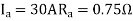
1) A 220-volt DC motor has an armature resistance of 0.75 ohm. It is drawing and armature current of 30 A, driving a certain load. Calculate the induced EMF in the motor under this condition. V=200V Are the given values For a motor, V= 220=
This is the induced EMF called a back EMF in a motor |


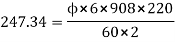
2) Find the useful flux per pole on no load of a 250V 6 pole shunt motor having two circuit connected armature winding with 225 conductors.at normal working temperature the overall armature resistance including brushes is 0.2 ohm. The armature current is 13.3A at the no load speed of 908 RPM.
Solution V=250 P=6 Z=220 A=2 As two circuit armature
| |
N=908 p.m. For a DC shunt motor
250= Back emf
| |


Power equation of a DC motor
The voltage equation of a DC motor is given by
V= |

Multiplying both sides of the above equation by 
V |


This equation is called as power equation of a DC motor
V =net electric power input to the armature measured in watts
 power loss due to the resistance of the armature called armature copper loss.
So difference between V and
and  is input losses gives the o/p of the armature.
So  is called electric equivalent of gross mechanical power developed by the armature.
This is denoted as 
Therefore, I/P to the armature-armature copper loss = gross mechanical power developed in the armature
|
DC shunt motor
|
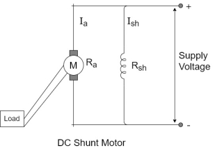
In this type the field winding is connected across the supply as shown in figure
Let  be the resistance of shunt field winding and
  be the resistance of armature winding.
The value of  very small while
  is quite large. Hence shunt field winding has more number of turns with less cross sectional area.
Applications of DC motors (simple numerical problems)
Voltage and current relationship
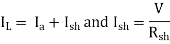
The voltage across armature and field winding is same equal to the supply voltage V.
The total current drawn from the supply is denoted as line current
|

Now flux produced by the field winding is proportional to the current passing through it i.e. 
|

As long as supply voltage is constant which is generally so in practice, the flux produced is constant.
Hence D.C. shunt motor is called constant flux motor.
DC series motor
|
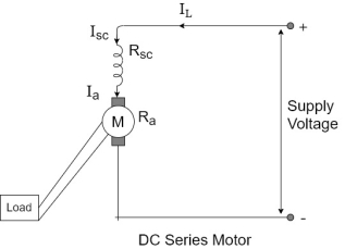
In this type of motor, the series field winding is connected in series with armature and the supply as shown in figure. Let  the resistance of all the series field winding then the value of
  is very small and it is made up of small number of turns having large cross section area.
Voltage and current relationship
Let So
And,.
|


Supply voltage has to overcome the drop across series field building in addition to  drop across armature winding.
In series motor entire armature current is passing through the series field winding. So flux produced is proportional to the armature current.
 for series motor
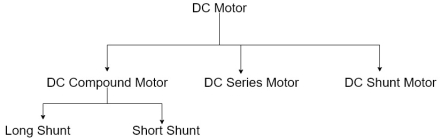
DC compound motor
The compound motor consists of part of the field winding connected in series and part of the field winding connected in parallel with the armature.it is further classified as short shunt compound and long shunt compound motor.
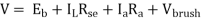
Long shunt compound motor
In this type the shunt field winding is connected across the combination of armature and the series field winding as shown in figure
|
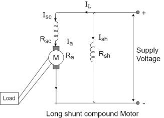
Voltage and current relationship
Let  be the resistance of series field and
  resistance of shunt field winding.
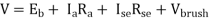
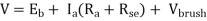
The total current drawn from supply is So ,. But, And, V= But as
|


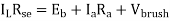
Short shunt compound motor
In this type the shunt field is connected properly in in parallel with armature and the series field is connected in series with the combination as shown in figure.
|
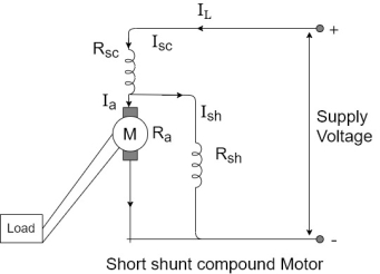
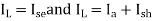
The entire line current is passing through the series field winding
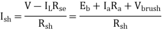
Now the drop across the shunt field winding is to be calculated from the voltage equation
But,
Drop across shunt field winding=V-
|

A long shunt compound motor can be of cumulative or differential type. Similarly, short shunt compound motor can be cumulative order differential type.
Torque and speed equations
Before analysing the various characteristics of motors, latest device the torque and speed equations as applied to various types of motors
 for the torque equation
This is because  to a constant for a given motor.
Now  is the flux produced by the field winding and is proportional to the current passing through the field winding.
|

For a D.C. shunt motor.  Is constant as long as supply voltage is constant. Hence flux is also constant.
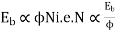
 for shunt motors
For DC series motor  same as
  . Hence flux is proportional to the armature current
| ||
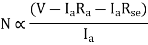
For series motor lly as We can write the speed equation as
So for shunt motor the flux is constant
While for series motor flux is proportional to | ||
| ||


These relations play an important role in understanding the various characteristics of different type of motors.


