The types of loads acting on structures for buildings and other structures can be broadly classified as vertical loads, horizontal loads and longitudinal loads. The vertical loads consist of dead load, live load, and impact load.
Types of loads acting on the building structure.
- Dead load
- Imposed loads
- Wind loads
- Snow Loads
- Earthquake forces
- Shrinkage, creep and temperature effect
- Other forces and effects
Dead Load
The Dead loads in the building include the weight of all permanent constructions, like roofs, floors, walls, partition walls, beams, columns, balcony’s footing.
These loads assessed by estimating the quantity of each material and then multiplying it with the unit weight. The unit weights of various materials used in building constructions also give in the code IS875 -1987. It includes an exhaustive list.
Imposed Loads
The loads which keep on changing from time to time are called imposed loads. Common examples of such loads in a building are the weight of the persons, weights of the movable partition, dust loads and weight of the furniture. Their loads formerly known as live loads. These loads are to suitably assumed by the designer. It is one of the major loads in the design. The minimum values to assumed are given in IS 875-1987. It depends upon the intended use of the building. These values presented for square more of the floor area. The code gave the value of loads for the following occupancy classification:
- Residential building
- Education building
- Institutional building
- Business and office building
- Mercantile buildings
- Assembly buildings
- Industrial buildings
- Storage rooms
The code gives uniformly distributed loads as well as concentrated loads. The floors are to investigate for both uniformly distributed and worst position of concentrated loads. The one which given worst effect is to consider for the design but both should not consider acting simultaneously.
In a particular building, the Imposed load may change from room to room.
Load Bearing Construction
- Almost all the walls are load bearing walls.
- Almost all the should be provided with foundation
- Load bearing walls are taken deep into the subsoil foundation.
- Any load bearing wall should have minimum thickness of 200 mm.
- Wall are usually constructed of bricks or stone
- In a multi-storeyed building for every wall in the floor above there must be a corresponding wall in continuation in the floor below to support it.
- In a multi – storeyed building the thickness of the wall increase as we descend from a floor above to one below it.
- A load bearing wall once constructed shall remain in position and should never be dismantled in full or part.
- This type of construction does not favour too many openings for windows, doors, ventilation etc., in the ground floor as required for show room etc., as the load bearing length of wall is considerably reduced.
- In case of multi – storeyed buildings, the room area is reduced as we go down due to thicker walls.
- Plans of the different floors must be the same. Very little changes are only possible between one floor and the one above.
- May not withstand seismic forces and other forces and other type of vibration because composed of different blocks as bricks and stones being bonded together.
Framed Construction
- None of the wall are load bearing. They serve the same purpose as partition or screen.
- None of the walls are provided with any type of foundation. Walls do not go below the plinth beam.
- Only column are taken deep into subsoil and provided with foundation footing.
- Exterior wall subjected to weathering elements are generally 200 mm thick. All other wall can be 100 mm thick or even thinner.
- Column supporting beam supporting slab are all of R.C. C.
- There is no such necessity. As none of the walls are load bearing. Every floor may have wall independent of the one below it.
- These walls do not take the load and need not be thicker. They may not even continue in the floor below.
- The wall of framed structure can be displaced at will as they are lighter and non load bearing.
- The space between column can remains as open space as the case with multi – storeyed residential flats where the ground floor is left with no walls for easy parking of vehicle.
- Thickness of wall remains uniform, therefore the carpet area in any floor remains the same.
- Plans of different floor are independent of each floor. The ground floor may have a commercial complex, first floor an office or a bank and second floor onward of residential complexes of different types of plans and function within the same building.
- More rigid and withstand seismic forces because of the entire frame of column, beam and slabs act as one unit of R.C.C.
There are two types of structure to be design and analysis in civil engineering they are statically determinate and indeterminate structures.
Statically Determinate Structure If the structure can be analysed by use of the equation of equilibrium is known as statically determinate structure. The equation of equilibrium are
- Sum of horizontal force is zero
- Sum of vertical force is zero
- Sum of the moment about any point is zero.
∑FX = 0
∑FY = 0
∑M = 0
Statically indeterminacy structure:
The structure, which cannot be analyzed by just using the equation of equilibrium, is known as a statically indeterminate structure.
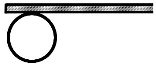
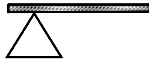
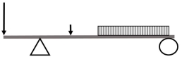
Example of statically determinant structure
|
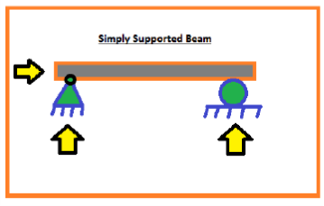
At (A) it is hinged support and at (B) it has roller support.
So, In the above beam, the reaction occurred at A isvertically upward and also in a horizontal direction. Becausehinge support has two reactions.
But, the reaction occurred at B is only one reaction which is vertically upward.
So, in the above beam, totally three unknown reaction which istwo reactions at support (A) and one unknown reaction at (B).
So, this beam can be analysed with the help of those three equilibrium reaction.
If the number of unknown reactions is less than or equal toequilibrium reaction
i.e three then the structure can beeasily analyzed. and this structure is known as a staticallydeterminant structure.
Analysing is to calculate the shear force and bending momentof the structure.
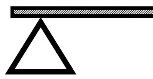
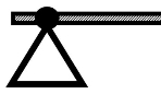
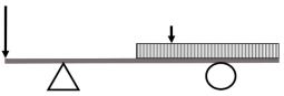
Example of statically indeterminate structure.
|
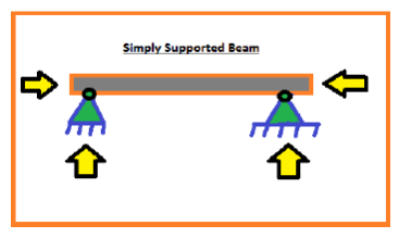
The above beam, It has two hinge support in which, (A) has tworeactions and (B) has also two reactions.
So, the total unknown reaction is four which is greater thanthe equilibrium equation which is only three.
So, we cannotanalyze this structure. So, these types ofstructures are known as statically indeterminant structures.
If you see in the residential building then all the memberslike a beam, column, slabs are fixed with each other. So, theyhave a more unknown reaction than the equilibrium equationwhich is three.
Hence, they are statically indeterminate structure.
I hope you understood all about difference between Staticallydeterminate and indeterminate structures.
Beam types: | |||||||||||||||||||||||||||||||||||||||||||||||||||||||||||||||
| |||||||||||||||||||||||||||||||||||||||||||||||||||||||||||||||


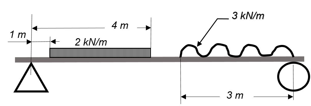
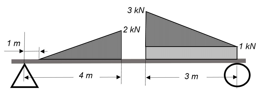
Solving for beam reactions
When solving for reactions, the following steps are recommended:
- Draw the beam free body diagram
- Replace the uniform distributed load (if any) with the equivalent point load
- Solve ΣMA = 0 (sum of moments about support A). This will give you RB (reaction at support B).
- Solve ΣMB = 0. This will give you RA.
- Using RA and RB found at steps 3 and 4 check if ΣV = 0 (sum of all vertical forces) is satisfied.
- Note that steps 4 and 5 can be reversed.
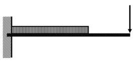
- For a cantilever beam use ΣV = 0 to find the vertical reaction at the wall and ΣMwall = 0 to find the moment reaction at the wall. There is no other equation to validate your results.
Assumptions in cable Analysis :
- Cables are considered as inextensible
- Self weight of cable is neglected.
- Loads acting on cables are concatenated ( point loads) load.
- Supports are hinged support
- Deflected shape of cables between the two load points is a straight line.
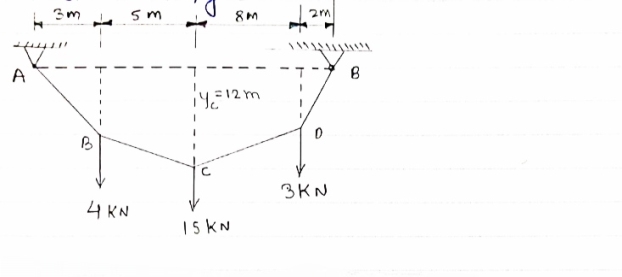
- Determine the tension in segment of cable as shown in figure
|
Draw FBD of cable system.
|
For the equilibrium of entire cable system ∑MA = 0
 RVE
RVE 18) = 0
12 + 120 + 48 - 18 RVE = 0
180 = 18 RVE
RVE = 10 KN
Using ∑Fy = 0
 RVA – 4 – 15 – 3 + RVS = 0
RVA + RVE = 22
 RVA = 12 KN
 ∑Fx = 0
RHE – RHA = 0
 RHE = RHA ………..①
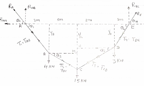
- Now as we have taken the moment about point A, let us consider cable system EDC, because the say of point C is known
FBD of cable EDC is shown below
For the equilibrium
∑MC = 0
 taking moment
About point C
|
(3 8) – (RVE
 RHE
RHE = 0
= 0
24 – (10  10) + 12RHE = 0
 12RHE = 76
 RHE = 6.33 KN
From eqn①
RHA = 6.33 KN
- Now let us find out the angles made by cable with horizontal. i.e
 1 ,
1 , 2 ,
2 ,  3 ,
3 ,  4 and sag of each point
tan 1 =
1 = =
= 
 1 = tan -1
 = tan-1
 = 62.190
 tan
tan 1 =
1 =
 tan 62.19 =
  YB = 5.69 m
tan 2 =
2 = =
=  =
=  =
= 
 2 = tan-1
 2 = 51.610
now tan 4 =
4 =  =
= 
 4=
4=  =
= 
 4= tan-1
 = 57.670
  4 = 57.670
 tan 57.67 =
YD = 3.15 m
Also tan  3 =
3 = =
=  =
=  =
= 
 3 = tan-1
 3 = 47.90
- Now let us tension in each segment of cables
 T1 = TAB = RA =
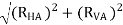
 T1 = TAB = RA =
 T1 = TAB = RA = 13.57 KN
Consider the equilibrium of point C, using lamis theorem,
|
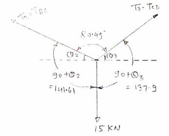

 T2 = 10.2 KN
T3 = 
 T3 = 9.45 KN
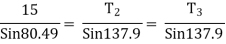
consider equilibrium of point D,
|
Using lamis theorem
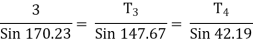
 T3 =
T3 =  = 9.45
 T3 = 9.45 KN
 T4 =
T4 = 
 T4 = 11.85 KN
 T1 = TAB = 13.57 Kn
 T2 = TBC = 10.2 KN
 T3 = TDC = 9.45 KN
 T4 = TDE = 11.85 KN
IF YC = 8m determine reaction at A and E and may tension in the cable
|
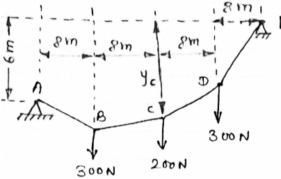
FDB for the cable loaded and supported will be as given below
|
For equilibrium of cable
∑MA = 0
 Y) + (6EX) = 0
 6EX -
6EX -  Y = - 12800 …….①
 ∑FY = 0
  AY + EY – 300 – 200 – 300
 AY + EY = 800 ………②
 ∑FX = 0
  - AX + EX = 0
  EX = AX ………③
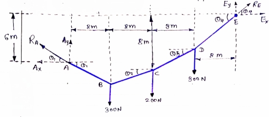
As distance of point C is known let us consider cable CDE, FBD will be as below
|
For equilibrium of cable (C D E),
 ∑MC = 0
 (300
(300  EX) – (16 EY) = 0
 8 EX - 16 EY = - 2400 ……….④
 6EX -
6EX -  Y = - 12800 …….①
 8 EX - 16 EY = - 2400 ……….④
Solving ① and ④ simultaneously
 EX = 800 N
EY = 500 N
| Direction of RE
|


From eqn② and ③
 AY + EY = 800
  AY = 250 N

 AX= EX
 AX = 800 N
 reaction at A, RA =
 RA = 838.15 N
Direction of RA
 1 = tan-1
 1 = 17.350
As EY > AY max tension will occur in cable part DE
 TDE = RE = 970.82 N max tension
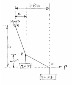
Cable ABC supports two Boxes as shown in figure
Knowing that b = 2.7m, find the required
Magnitude of horizontal force P and
Corresponding distance A
|
FBD of cable system is given below
|
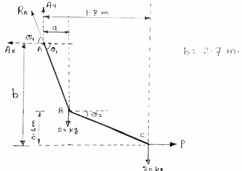
For equilibrium of cable

 ……….①
……….①
∑FY = 0  AY –
AY –  -
-  = 0
= 0
 AY = 490.6 N
∑FX = 0  - AY + P = 0
 AX = P
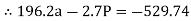
Now let us consider cable part BC, FBD is shown below
|
For equilibrium
∑MB = 0


 ……….②
……….②
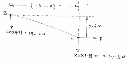
Solving eqn① and ②
196.2a – 2.7P = - 529.74
294.3a + 0.6P = 529.74
a = 1.22m
P = 284.81 N
- Frames
- Analysis of frames
Frame is a structure which consists of two or more members connected to each other by using pin joint in the frame at least one member is multiforce member.
Frames are stationary structure used to carry the load only.
Unlike the truss, forces can be applied anywhere on the members of frame.
In truss forces are applied at the joint only.
Members of frame are subjected to bending as well as tension and compression.
In the frame force acting on the members may not be collinear with the axis of members.
- Difference between Frame and Truss:
Truss
| Frame
|
Determine the force in member BD of the frame as shown In figure find reaction at C
|
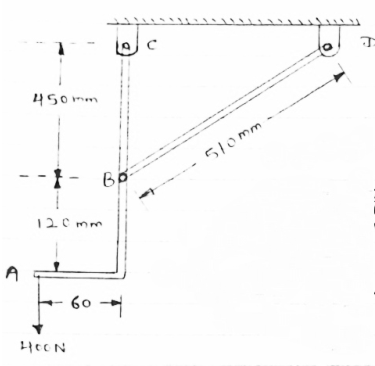
As in this frame there are 2 hinge supports therefore, 4 reactions cannot be calculated. So consider the FBD of each member directly and analyse the frame.
FBD of members ABC will be as given below
|
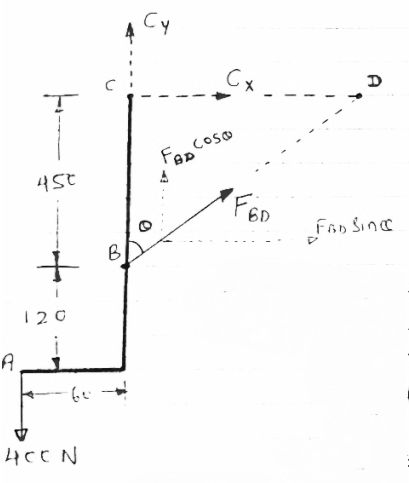
In  BCD
BCD
Cos  =
=  =
= 
 = 28.070
As a members BD is two force members, the force developed in the member BD i.e FBD is considered instead of two reactions at B.
Let FBDis tensile
For equilibrium,
∑MC = 0
 [(FBD Sin
 )
) –(400
–(400 60) = 0
 -(FBD Sin
 - 24000 = 0
-211.75 FBD = 24000
 FBD = - 113.34 N
∑FY = 0
 - 400 + CY +FBD Cos
 = 0
= 0
 - 400 + CY + (-113.34 Cos 28.07) = 0
 CY = 500 N
∑FX = 0
 FBD Sin
 + CX = 0
 (-113.34 Sin
 ) + CX = 0
 CX = 53.33 N
As FBD is negative, our assumption is wrong about the nature of FBD force
Thus FBDis not tensile but it is compressive force

FBD = 113.34 N ( C)
CY = 500 N
CX = 53.33 N
Reaction at C,
RC = 
 RC = 502.84 N
Angle of reaction RC
 = tan-1
 = 83.910
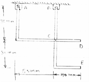
Determine the components of reactions at A and B if 60 N load applied at point D.
|
FBD of frame
|
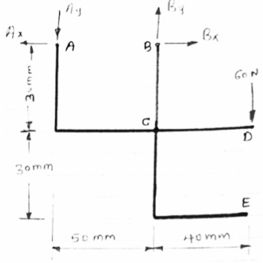
For the equilibrium of entire frame applying conditions of equilibrium.
 ∑MA = 0
 -(50 BY) + (60
  90) = 0
 BY = 180 N
|
|


Now let us separate the frame members and draw FBD of each membersseparately
|
|
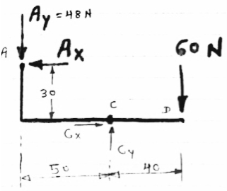
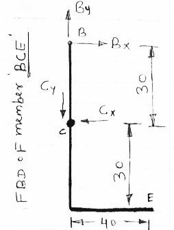
FBD of members ACD and BCE are shown above forces acting (reactions) at A,B,C are also shown
Let us apply conditions of equilibrium to members ACD
 ∑MA = 0
 - (AY
- (AY 50) – (AX
 30) + (60
  40) = 0
 - (48
- (48  50) – (30 AX) + 2400 = 0
 - 2400 – 30 AX + 2400 = 0
 AX = 0
 ∑FY = 0
 - AY + CY – 60 = 0
 - 48 + CY– 60 = 0
 CY = 108 N
 ∑FX = 0
 - AX + CX = 0
 CX = 0
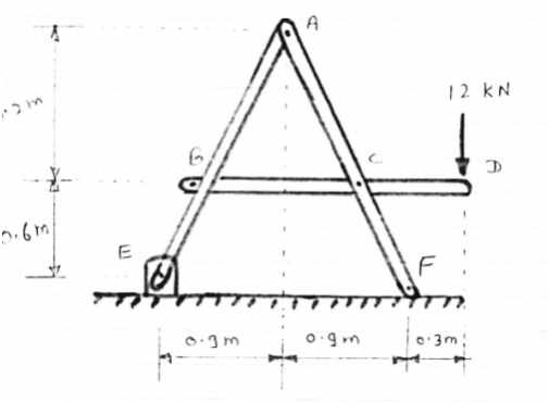
For the frame loaded and supported as shown in figure, determine the components of all forces acting on frame member ABE
|
Consider FBD of the given frame as shown below
|
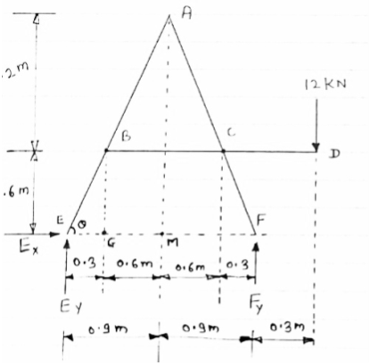
 Consider AEm
tan  =
= 
 =63.430
 In BEG
tan  =
= 
 EG = 0.3 m
 GM = 0.6 m
For equilibrium of frame,
 ∑ME =0
 - (1.8 FY) + (12
  2.1) = 0
 FY = 14 KN
 ∑FY =0
 EY + FY – 12 = 0
 EY + 14 – 12 = 0
 EY = -2KN = 2 KN
 ∑FX =0
  EY =0
EY =0
|
Consider FBD of member BCD,
For equilibrium.
 ∑FY =0
 1.2 CY + (12
  1.8) = 0
 CY = - 18 KN = 18 KN
∑FY =0
 BY – CY -12 = 0
 BY – (-18) – 12 = 0
 BY + 6 = 0
 BY = -6 KN = 6 KN
∑FX =0
 BX – CX = 0
 BX = CX ............①
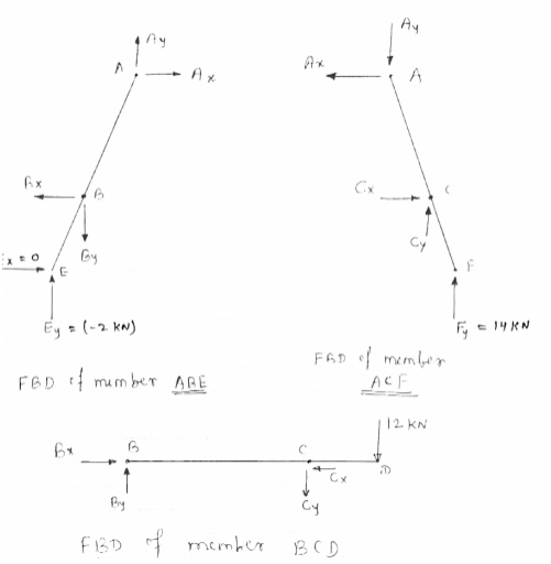
Now consider FBD of member ABE,
For equilibrium
∑MA =0
 -(BY
-(BY 0.6) + (EY
 0.9) + (BX
 1.2) - (EX
 1.8) = 0
 -0.6 BY + 0.9 EY + 1.2 BX = 0
 -0.6 (-6) + 0.9 (-2) + 1.2 BX = 0
 BX = -1.5 KN
∑FY =0
 EY - BY+ AY = 0
 (-2) – (-6) + AY = 0
 -2 + 6 + AY = 0
 AY = -4 KN = 4 KN
∑FX =0
 AX – BX= 0
 AX = -1.5 KN = 1.5 KN
 CX = -1.5 KN = 1.5 KN
- Consider FBD of member ACF
(just for check)
∑FX =0
 - AX + CX= 0
 -(-1.5) + (-1.5) = 0
 0 = 0
0 = 0  CHS = RHS
∑FY =0
 CY – AY + FY = 0
 -18 – (-4) + 14 = 0
 -18 + 18 = 0
0 = 0  LHS = RHS
Thus in member ACF,
∑FX =0
∑FY =0
 It is in equilibrium,
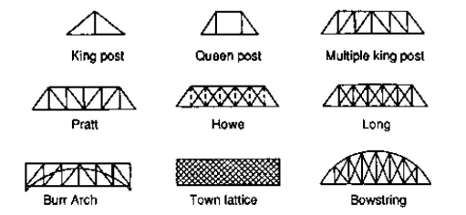
TYPES OF TRUSSES
- Simple truss – indicates a single triangular truss. These trusses are most often used as the roof trusses.
- Planar truss – as the name implies it is a two dimensional truss. If all the members and the nodes are in a planar surface, then this truss is a planar truss.
- Space frame truss – Contrast to planar truss, the members and the nodes are located in the three dimensional space. Electrical and telecom towers are the one of the simplest example that we are seeing in the day to day life.
Simple Truss: It is possible to create a simple truss by joining three bars together to form a triangle. We can increase the size of the truss by adding two more members with an additional joint. By repeating this process, we can develop simple trusses with different shapes as shown below. The triangular building block assures internal stability of the truss structure as it is increased in size.
|
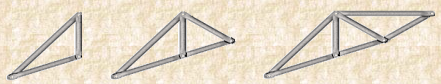
Although it is possible to have non-triangular cells in a simple truss, internal stability will not be guaranteed in that case.
Compound Truss: A compound truss is made up of simple trusses joined together to form a larger truss. The figure below shows a compound truss consisting of two simple trusses joined by a common joint and a bar. It is also possible to have multiple simple trusses joined together to create a larger compound truss. The connection of simple trusses then becomes a design issue determined based on the size of the resulting compound truss. Compound trusses are commonly used to support loads over long spans as in bridges.
|
Complex Truss: A complex truss uses a general layout of members different from that used in simple and compound trusses. It often incorporates overlapping members.
|
FORMS OF TRUSSES
1. Pratt truss
|
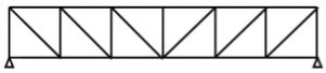
Pratt truss form for the loads in gravity direction
|
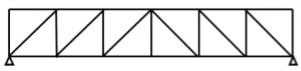
Pratt truss form for the uplift loads(loads opposite to gravity)
2. Warren truss
|

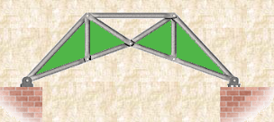
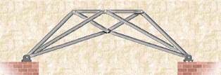
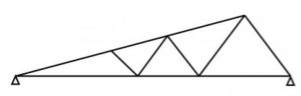
3. North light truss
|
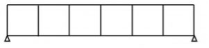
4. Vierendeel truss
|
King post truss, Bowstring truss, Queen post truss, Flat truss, Lenticular truss are some other forms of trusses in the use of the industry.
|
Question 1) Determine the forces in all members of truss by joint method
|
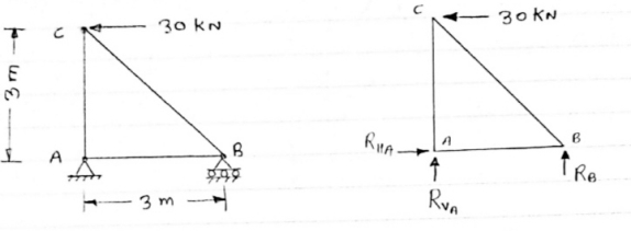
Answer 1) Consider FAB of Truss, Applying conditions of equilibrium,
 = 0
= 0
RHA + 30 Kn
 = 0
= 0
RvA + RB =0
Taking moment at point A, = 0
= 0
-(RB* 3) - (30*3) = 0
RB = -30 KN
RB =30 KN RVA = 30 KN
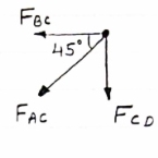
Consider Joint c, assuming forces in member AC & BC to be
Tensile, applying conditions of equilibrium,
|
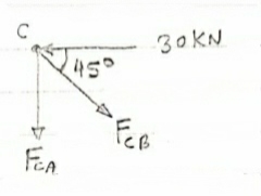
 = 0
= 0
-30 + FCB cos 45 =0
FCB =30/cos 45 = 42.42 KN (T)
-  = 0
= 0
- FcA – FCB sin 45=o
- F cA -42.42 sin 45 =0
- |
-
-FCA – 30= 0
-FCA = -30 KN
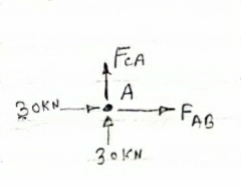
Consider Joint c, assuming forces in member AC & BC to be
Tensile, applying conditions of equilibrium,
 Fx = 0 30+FAB =0
FAB = -30KN
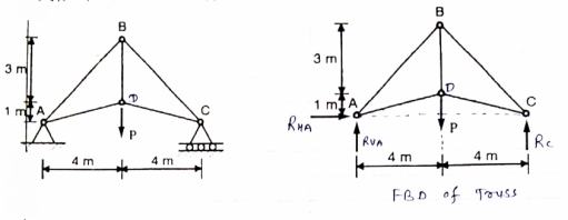
Question 2) Determine the forces in each member of the plane truss as shown in fig. in terms pf the external loading and state if the members are in tension or compression. Use 0+ 30 deg, L = 2 m and p =100N.
Diagram
|
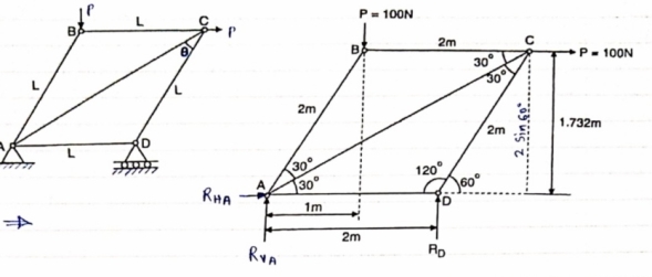
Answer 2) Consider FBD of Truss,
For equilibrium,  Fx =0
Fx =0
RHA+100 =0
RHA =-100 KN
 Fy =0 RVA = RD – 100 ….. 1
MA = 0 -------Taking moment @ A
- (Roxz) + (100*1) + (100*1.732) =0
- - 2 Rd + 100 + 1.7320 =0
- -2 Rd + 100 + 173.2 =0
- RD =136.66 N ()
From eqn (1)
RVA = 100 – 136.6
RVA= 36.6N
RVA = 36.6 N
Consider Joint D, for equilibrium,
Fx =0
-FAD + FCD cos 60 =0 – (11)
Fy = 0
136.6 +FCD sin 60 +0
|
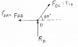
FCD = -157.73 N ©
From equation (11), Fad =- 78. 87 N (c)
Consider point A, for the equilibrium of point A,
 Fx = 0
- 100 + FAD + FAc cos + 30 FAb cos60 = 0
-100 + (-78.87) +FAC cos 30 +FAb cos60 =0
FAc cos 30 + FAB cos60 + 178. 87 (3)
|
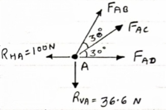
 fx =0
fx =0
-36.6 + FAC sin 30 + FAB sin 60 =0
FAC sin 30 + FAb sin 60 = 36.6
Solving equation (3) and (4)
FAC = 273.21 N (T)
FAB = -115.47 N
FAB= 115.47 N ©
Consider point B, for the equilibrium of point,
 Fx =0
Fx =0
-FAB cos60 + FBC =0
-[9-115.47) cos60]+ FBC =0
|
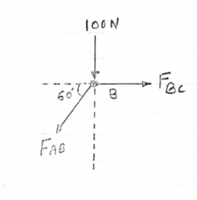
FBC = -57.73 N
FBC =57.73N
Member | AB | BC | CD | AD | AC |
force | 115.47N | 57.73N | 157.73N | 78.87N | 273.21N |
Nature | c | c | c | c | T |
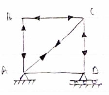
Question 3) Determine the axial forces in each member of the plane truss as shown in figure.
|
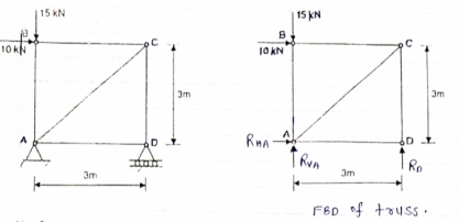
Answer 3) consider FBD of Truss,
For the equilibrium of Truss,  fx =0
fx =0
RHA + 10 =0
RHA = -10 KN
RHA =10KN (
Resolving forces vertically,
 fy =o
fy =o
RVA + RD -15 =0
RVA + RD = 15 …… (1)
Taking moment about point A,
 Fy =0
Fy =0
(10*3) – 3 Rd =0
30+ 3 Rd =0
RD= 10 KN 
RVA = 5KN ( )
)
Now Consider joint B, FBD of joint B is shown below.
Assuming forces developed in all members to be Termile,
For the equilibrium of joint we have
 fx =0
fx =0
10+FBC =0
|
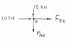
FBC = -10 KN
FBC = 10KN (c)
 fy =0
fy =0
FAB = -15 KN
FAB = 15 KN (c)
Now consider joint c,
For the equilibrium of joint,
 fx =0
fx =0
-FBC – FAC cos 45 =0
- (-10) – FAC cos 45=0
10= FAC cos 45
FAC = 10/cos 45
|
FAc = 14.14 KN (T)
 fy =0
fy =0
-Fac sin 45 – FCD=0
- 14.14 sin45 = FCD
FCD = -10 KN (c)
FCD= 10 KN (c)
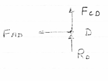
Consider joint D,
By observation,
FAD=0
|
Sr .No | Member | Force | Nature |
1 | AB | 15 KN | c |
2 | BC | 10KN | c |
3 | CD | 10KN | c |
4 | DA | 0 | - |
5 | AC | 14.14 | T |
|
Question 4) Member AB & BC can support a maximum compressive force of 800 N & members AD, DC, BD can support a max. Tensile. Force of 2000N Determine the greatest land p that
|
Answer 4) Consider following geometry of the figure.
|
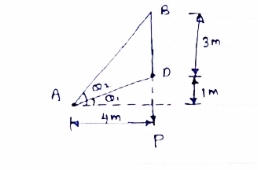
tan 1 = ¼
1 = ¼
 14.04
14.04
 2 =
2 =  =45
=45
Consider
 fx =0 RHA = 0
∈Fy =o RVA + Rc = p…(1)
∈ma =0
Hp- 8 Rc =0
Rc =P/2 N ( ) RvA = (P/2) N (
 )
)
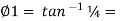
Consider point A C assuming all forces as Tensile)
∈fx =0
FAD cos 14.04+FAB cos 45 =0… (2)
∈fy = 0 p/2= Fad sin 14.04 + FAB sin 45 =0….. (3)
|
FAB = 2743.9 N > 800 N ( Not Allowed)
Let FAD = 2000 N (T) Then from eqn (2) & (3)
FAB =-274.9 N > 800 ( Not allowed)
Let FAB = .800 N ©, Then put this eqn (2) (3) we get
FAB = 583 N < 2000 N (Allowed) From Eqn (2) P= 848.9 N
Method of joint: This method involves isolating each joint of the truss and considering the equilibrium of the joint when determining the member axial force. Two equations used in determining the member axial forces are ∑ Fx = 0 and ∑ Fy = 0. Joints are isolated consecutively for analysis based on the principle that the number of the unknown member axial forces should never be more than two in the joint under consideration in a plane trust.
Analysis of Trusses by Method of Joint
This method is based on the principle that if a structural system constitutes a body in equilibrium, then any joint in that system is also in equilibrium and, thus, can be isolated from the entire system and analyzed using the conditions of equilibrium. The method of joint involves successively isolating each joint in a truss system and determining the axial forces in the members meeting at the joint by applying the equations of equilibrium. The detailed procedure for analysis by this method is stated below.
Procedure for Analysis
•Verify the stability and determinacy of the structure. If the truss is stable and determinate, then proceed to the next step.
•Determine the support reactions in the truss.
•Identify the zero-force members in the system. This will immeasurably reduce the computational efforts involved in the analysis.
•Select a joint to analyse. At no instance should there be more than two unknown member forces in the analysed joint.
•Draw the isolated free-body diagram of the selected joint, and indicate the axial forces in all members meeting at the joint as tensile (i.e. as pulling away from the joint). If this initial assumption is wrong, the determined member axial force will be negative in the analysis, meaning that the member is in compression and not in tension.
•Apply the two equations Σ Fx = 0 and Σ Fy = 0 to determine the member axial forces.
•Continue the analysis by proceeding to the next joint with two or fewer unknown member forces.
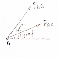
|
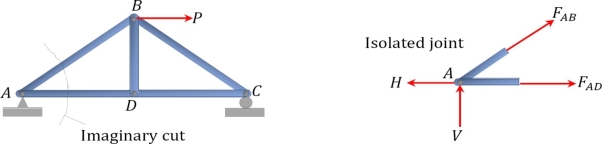
Method of section: This method entails passing an imaginary section through the truss to divide it into two sections. The member forces are determined by considering the equilibrium of the part of the truss on either side of the section. This method is advantageous when the axial forces in specific members are required in a truss with several members.
|
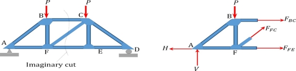
Analysis of Trusses by Method of Section
Sometimes, determining the axial force in specific members of a truss system by the method of joint can be very involving and cumbersome, especially when the system consists of several members. In such instances, using the method of section can be timesaving and, thus, preferable. This method involves passing an imaginary section through the truss so that it divides the system into two parts and cuts through members whose axial forces are desired. Member axial forces are then determined using the conditions of equilibrium. The detailed procedure for analysis by this method is presented below.
Procedure for Analysis of Trusses by Method of Section
•Check the stability and determinacy of the structure. If the truss is stable and determinate, then proceed to the next step.
•Determine the support reactions in the truss.
•Make an imaginary cut through the structure so that it includes the members whose axial forces are desired. The imaginary cut divides the truss into two parts.
•Apply forces to each part of the truss to keep it in equilibrium.
•Select either part of the truss for the determination of member forces.
•Apply the conditions of equilibrium to determine the member axial forces.
References:-
- R. C. Hibbler, Engineering Mechanics: Principles of Statics and Dynamics, Pearson Press
- Bansal R. K., A Text Book of Engineering Mechanics, Laxmi Publications.


