UNIT-3
TRIGONOMETRIC LEVELLING
In this method, the difference in elevation between two points can be found by measuring the inclined or horizontal distances and the zenith or altitude angles is called trigonometric
It is of 2 types:-
1.plain trigonometric levelling: the principle of plain surveying are employed .it is assumed that the distance measured is small compared to the radius of earth and thus the effect of earth curvature and refraction can be ignored
2.Geodetic trigonometric levelling: In this method, the distance between the points is comparable to that of earth radius and thus the simple principles of plain surveying cannot be applied.it requires the correction due to earth curvature and refraction.
Case (1) if horizontal distance up to the point can be mean.
|
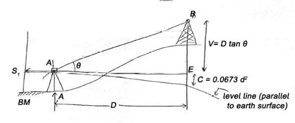
Fig-1 if horizontal distance up to the point can be mean
Given values:-
- Distance 'D'
- Angle=
- Staff reading
Vertical height
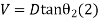
V = D tan
R.L. of B = RL of B.M. +
C= combined correction due to Earth curvature/ refraction
= (+) 0.0673 [positive for RL]
Case (2) If distance D cannot be measured
Given (known) values:-
- Distance 'B' = AB
- Staff readings
The difference between staff readings
3 Angle measured
3. From 
4. From 
4 RL of BM
|
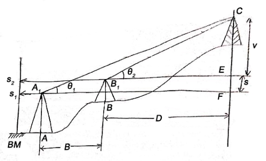
Fig-2 If distance D cannot be measured

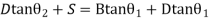
V+S=(B+D)tanθ1 (1)


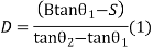

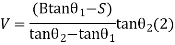
RL of 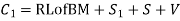
DETERMINE THE ELEVATION OF THE OBJECT BY SINGLE PLANE METHOD
Aim:
To find out the Reduced Level (R.L.) of inaccessible elevated point by Trigonometrical Levelling.
Instruments required:
Theodolite, Levelling staff, Ranging rod, Tape.
Given data:
Elevation of B.M. = 100.000 m
General:
(a)Trigonometry is the process of determining the differences of elevation of the stations from observed vertical angles and known horizontal distance either measured directly or computed trigonometrically.
(b) Instruments stations and the elevated object are in the same plane.
Procedure:
1. Set up the theodolite at A, level it carefully and observe the angle of elevation a1.
2. Set the vertical vernier to zero, and take a reading on a staff held vertically on a BM. Let it be S1
3. Transit the telescope, so that the line of sight is reversed.
4. Mark a point B in the line of sight at a convenient distanced, Measure it accurately,
5. Shift the theodolite to point B, Centre it and level it. Observe the angle of elevation a2.
6. Set the vertical vernier to zero and take again a B.M., reading as S2.
When it is not possible to measure the horizontal distance between the instrument station and the base of the object, this station and the base of the object, this method is employed to determine the R.L of the object
DETERMINE THE ELEVATION OF THE OBJECT BY double PLANE METHOD
Aim:
To find out the R.L. of the inaccessible elevated point by Trigonometrical Levelling with the instrument at double vertical plane.
Instruments Required:
Theodolite, Levelling staff, Ranging rod, Tape.
Given Data:
R.L. of the B.M. = 100. 000m.
General:
Instrument stations and the elevated objects are in different planes.
Procedure:
1. Let the given point is “B”
2. Set up the theodolite station A, centre it carefully and fix the ranging rod at C of known distance “d”
3. Measure horizontal angles BAC, Let it be q1, in angles BAC should be individually equal to 30° to 75°.
4. Sight ‘B’ the top of the object and observe the angle of elevation a1 ensuring that altitude bubble is centre of its run.
5. Setting the vertical vernier to zero take a reading on a staff held vertically on a benchmark. Let the reading be S1.
6. Shift the theodolite the station C at a known distance ‘d’ and centre it over the mark and observe that the horizontal angle BCA. Let it be q2.
7. Sight ‘B’ the top of the object and observe the angle of elevation a2, ensuring that the altitude bubble is central of its run.
8. Setting up the vertical vernier to zero takes a reading on a staff on the same benchmark. Let it be S2.
9. Measure the horizontal distance ‘d’ between stations A and C.
Total Station and its features
A total station is an electronic/optical instrument used in modern surveying and building construction that uses electronic transit theodolite in conjunction with electronic distance meter (EDM). It is also integrated with microprocessor, electronic data collector and storage system.
The instrument is used to measure the sloping distance of the object to the instrument, horizontal angles and vertical angles. This Microprocessor unit enables for computation of data collected to further calculate the horizontal distance, coordinates of a point and reduced level of the point.
Data collected from the total station can be downloaded into computer/laptops for further processing of information.
Total stations are mainly used by land surveyors and civil engineers, either to record features as in topographic surveying or to set out features (such as roads, houses or boundaries). They are also used by archaeologists to record excavations and by police, crime scene investigators, private accident Reconstructionist and insurance companies to take measurements of scenes.
- Missing line measurement (MLM}
- Control Survey (Traverse).
- Archaeologists use a total station to record excavations and its details
- Height measurement (Remove elevation measurement- REM).
- Resection is easy by total station.
- Remote Distance Measurement (RDM)
- General-purpose of angle and distance measurement
- detailed maps
Uses of Total Station:-
Total Station uses in the following areas:-
- Road Survey
- Rail Survey
- Canal Survey
- My Survey
- Engineering Survey
- Large Scale Survey
Parts of a Total Station
There are mainly four main components which are
- EDM (Electronic Distance Measurement),
- electronic theodolite,
- microprocessor and
- electronic display
Accessories of Total Station
Accessories of the total station are as follows:-
- Total Station Battery & Charger,
- Total Station Prism,
- Total Station Tripod & Bipod,
- Total Station Prism Pole and
- Stand For Total Station.
Advantages of Using Total Stations:-
- Fieldwork is very fast as compared to the conventional survey.
- The calculation is also fast and accurate.
- Accuracy is very high.
- Manual errors can be eliminated.
- Computers can use for map making and contour and its cross-sections
Applications of Total Station:-
the following application of total station are as given below:-
- Detail survey is carried out easily by this technique.
- Missing Line Measurement (MLM)
- Plotting of contours
- Carrying out controlled surveys
- Used to fix the missing pillars and column.
- Area calculations
Field Procedure for Total Station
Basic Steps involved in Total station surveying
Step-1: Setting up the of the instrument along with the tripod
Step-2: Levelling of the instrument approximately with the help of “bull’s eye bubble” and then verifying the levelling electronically
Step-3: Adjustment of reticle focus and image.
Step-4: Recording all the measurements
Step-5: Data Processing
Step 1: Tripod Setup tripod legs should be equally space tripod head should be approximately levelnHead should be directly over survey point
Step 2: Mount Instrument on TripodnPlace Instrument on Tripod secure with centring screw while bracing the instrument with the other hand insert battery in the instrument before levelling
Step 3: Focus on Survey PointnFocus the optical plummet on the survey point
Step 4: Leveling the InstrumentnAdjust the levelling foot screws to centre the survey point in the optical plummet reticle centre the bubble in the circular level by adjusting the tripod legs
Step 4: Leveling ... loosen the horizontal clamp and turn instrument until plate level is parallel to 2 of the levelling foot screws centre the bubble using the levelling screws- the bubble moves toward the screw that is turned clockwise rotate the instrument 90 degrees and level using the 3rd levelling screw
Step 4: Leveling ... nObserve the survey point in the optical plummet and centre the point by loosening the centring screw and sliding the entire instrument after re-tightening the centring screw check to make sure the plate level bubble is level in several directions
Step 5: Turn on the instrument by pressing and holding the “on” button The opening screen will be the “MEAS” screen. Select the Tilt function and then adjust the foot level screws to exactly centre the electronic “bubble
Total Station Errors:-
1 CALIBRATION OF TOTAL STATIONS
Maintaining the high level of accuracy offered by modern total stations, there is much more emphasis on monitoring instrumental errors, and some construction sites require all instruments to be checked regularly using procedures outlined in the quality manuals.
Some instrumental errors can be eliminated by observing on two faces of the total station and averaging, but because one face measurements are the preferred method on-site, it is important to determine the amount
of instrumental errors and correct for them.
For total stations, instrumental errors are measured and corrected by electronic calibration procedures that are carried out at any time and are applied to the instrument on-site.
Since calibration parameters can change due to mechanical shock, temperature changes and rough handling of the high-precision instrument, an electronic calibration should be carried out on a total station as follows:
- Before using the instrument for the first time
- After long storage periods
- After rough or long transportation
- After long periods of work
- Following big changes in temperature
- Regularly for precision surveys
Before every calibration, it is essential to allow the total station enough to reach the ambient temperature.
2 HORIZONTAL COLLIMATION (OR LINE OF SIGHT ERROR)
This axial error happens when the line of sight is not perpendicular to the tilting axis. It affects all horizontal circle readings and increases parallel to steep sightings, but this is eliminated by observing on two faces. For single face measurements,
an on-board calibration function is used to determine c, the deviation between the actual line of sight and a line perpendicular to the tilting axis. A correction will be applied automatically for this to all horizontal circle readings.
|
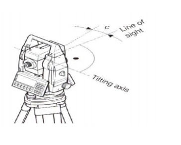
Fig-3 LINE OF SIGHT ERROR
3 TILTING AXIS ERROR
axial errors occur when the tilting axis of the total station is not perpendicular to its vertical axis, this does not affect sightings taken when the telescope is horizontal but produces errors into horizontal circle readings when the telescope is tilted, especially for steep sightings.
But with horizontal collimation error, this error is erased by two face measurements, or the tilting axis error (a) is measured in a calibration procedure and a correction applied for this to all horizontal circle readings.
4 COMPENSATOR INDEX ERROR
Errors that were caused by not levelling a theodolite or total station carefully cannot be eliminated by taking face left and face right readings. If the total station is fitted with a compensator it will measure residual tilts of the instrument and will apply corrections to the horizontal and vertical angles for these.
All compensators will have a longitudinal error l and traverse error t known as zero-point errors which are averaged using face left and face right readings but for a single face, readings must be determined by the calibration function of the total station.
|
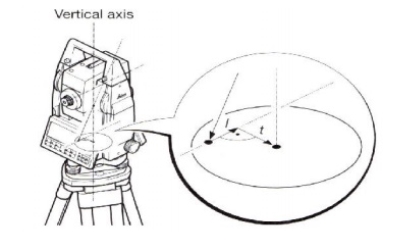
Fig-4 COMPENSATOR INDEX ERROR
A vertical collimation error exists on a total station if the 0o to 180o line in the vertical circle does not coincide with its vertical axis and this zero point error is present in all vertical circle readings and like the horizontal collimation error, it is eliminated by taking FL and FR readings or by determining i
Any difference between the measured horizontal and vertical angles is then identified as an instrumental error and applied to all readings. The total station is thus calibrated and the procedure is the same for all of the error type.
|
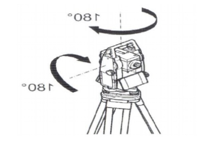
Fig-4 COMPENSATOR INDEX ERROR (correction)
Reference:
1 Madhu, N, Sathikumar, R and Satheesh Gobi, Advanced Surveying: Total Station, GIS and Remote Sensing, Pearson India, 2006.
2 Manoj, K. Arora and Badjatia, Geomatics Engineering, Nem Chand & Bros, 2011
3 Bhavikatti, S.S., Surveying and Levelling, Vol. I and II, I.K. International, 2010
4 Chandra, A.M., Higher Surveying, Third Edition, New Age International (P) Limited, 2002.
5 Anji Reddy, M., Remote sensing and Geographical information system, B.S.


