Input/Output Organization
An I/O system is required to take an application I/O request and send it to the physical device, then take whatever response comes back from the device and send it to the application. I/O devices can be divided into two categories −
- Block devices − A block device is one with which the driver communicates by sending entire blocks of data. For example, Hard disks, USB cameras, Disk-On-Key etc.
- Character devices − A character device is one with which the driver communicates by sending and receiving single characters (bytes, octets). For example, serial ports, parallel ports, sounds cards etc
Device drivers are software modules that can be plugged into an OS to handle a particular device. Operating System takes help from device drivers to handle all I/O devices.
The Device Controller works like an interface between a device and a device driver. I/O units (Keyboard, mouse, printer, etc.) typically consist of a mechanical component and an electronic component where electronic component is called the device controller.
There is always a device controller and a device driver for each device to communicate with the Operating Systems. A device controller may be able to handle multiple devices. As an interface its main task is to convert serial bit stream to block of bytes, perform error correction as necessary.
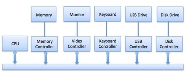
Any device connected to the computer is connected by a plug and socket, and the socket is connected to a device controller. Following is a model for connecting the CPU, memory, controllers, and I/O devices where CPU and device controllers all use a common bus for communication.
|
Fig 1 – Control device
Synchronous vs asynchronous I/O
- Synchronous I/O − In this scheme CPU execution waits while I/O proceeds
- Asynchronous I/O − I/O proceeds concurrently with CPU execution
The CPU must have a way to pass information to and from an I/O device. There are three approaches available to communicate with the CPU and Device.
- Special Instruction I/O
- Memory-mapped I/O
- Direct memory access (DMA)
This uses CPU instructions that are specifically made for controlling I/O devices. These instructions typically allow data to be sent to an I/O device or read from an I/O device.
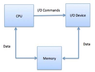
When using memory-mapped I/O, the same address space is shared by memory and I/O devices. The device is connected directly to certain main memory locations so that I/O device can transfer block of data to/from memory without going through CPU.
|
Fig 2 – I/O commands
While using memory mapped IO, OS allocates buffer in memory and informs I/O device to use that buffer to send data to the CPU. I/O device operates asynchronously with CPU, interrupts CPU when finished.
The advantage to this method is that every instruction which can access memory can be used to manipulate an I/O device. Memory mapped IO is used for most high-speed I/O devices like disks, communication interfaces.
Slow devices like keyboards will generate an interrupt to the main CPU after each byte is transferred. If a fast device such as a disk generated an interrupt for each byte, the operating system would spend most of its time handling these interrupts. So, a typical computer uses direct memory access (DMA) hardware to reduce this overhead.
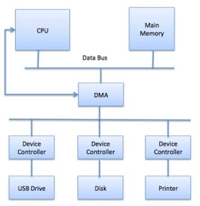
Direct Memory Access (DMA) means CPU grants I/O module authority to read from or write to memory without involvement. DMA module itself controls exchange of data between main memory and the I/O device. CPU is only involved at the beginning and end of the transfer and interrupted only after entire block has been transferred.
Direct Memory Access needs a special hardware called DMA controller (DMAC) that manages the data transfers and arbitrates access to the system bus. The controllers are programmed with source and destination pointers (where to read/write the data), counters to track the number of transferred bytes, and settings, which includes I/O and memory types, interrupts and states for the CPU cycles.
|
Fig 3 - DMA
The operating system uses the DMA hardware as follows −
Step | Description |
1 | Device driver is instructed to transfer disk data to a buffer address X. |
2 | Device driver then instruct disk controller to transfer data to buffer. |
3 | Disk controller starts DMA transfer. |
4 | Disk controller sends each byte to DMA controller. |
5 | DMA controller transfers bytes to buffer, increases the memory address, decreases the counter C until C becomes zero. |
6 | When C becomes zero, DMA interrupts CPU to signal transfer completion. |
Polling vs Interrupts I/O
A computer must have a way of detecting the arrival of any type of input. There are two ways that this can happen, known as polling and interrupts. Both of these techniques allow the processor to deal with events that can happen at any time and that are not related to the process it is currently running.
Polling is the simplest way for an I/O device to communicate with the processor. The process of periodically checking status of the device to see if it is time for the next I/O operation, is called polling. The I/O device simply puts the information in a Status register, and the processor must come and get the information.
Most of the time, devices will not require attention and when one does it will have to wait until it is next interrogated by the polling program. This is an inefficient method and much of the processors time is wasted on unnecessary polls.
Compare this method to a teacher continually asking every student in a class, one after another, if they need help. Obviously the more efficient method would be for a student to inform the teacher whenever they require assistance.
An alternative scheme for dealing with I/O is the interrupt-driven method. An interrupt is a signal to the microprocessor from a device that requires attention.
A device controller puts an interrupt signal on the bus when it needs CPU’s attention when CPU receives an interrupt, It saves its current state and invokes the appropriate interrupt handler using the interrupt vector (addresses of OS routines to handle various events). When the interrupting device has been dealt with, the CPU continues with its original task as if it had never been interrupted.
Operating System - I/O software’s
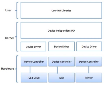
I/O software is often organized in the following layers −
- User Level Libraries − This provides simple interface to the user program to perform input and output. For example, stdio is a library provided by C and C++ programming languages.
- Kernel Level Modules − This provides device driver to interact with the device controller and device independent I/O modules used by the device drivers.
- Hardware − This layer includes actual hardware and hardware controller which interact with the device drivers and makes hardware alive.
A key concept in the design of I/O software is that it should be device independent where it should be possible to write programs that can access any I/O device without having to specify the device in advance. For example, a program that reads a file as input should be able to read a file on a floppy disk, on a hard disk, or on a CD-ROM, without having to modify the program for each different device.
|
Fig 4 – Process state
Device drivers are software modules that can be plugged into an OS to handle a particular device. Operating System takes help from device drivers to handle all I/O devices. Device drivers encapsulate device-dependent code and implement a standard interface in such a way that code contains device-specific register reads/writes. Device driver, is generally written by the device's manufacturer and delivered along with the device on a CD-ROM.
A device driver performs the following jobs −
- To accept request from the device independent software above to it.
- Interact with the device controller to take and give I/O and perform required error handling
- Making sure that the request is executed successfully
How a device driver handles a request is as follows: Suppose a request comes to read a block N. If the driver is idle at the time a request arrives, it starts carrying out the request immediately. Otherwise, if the driver is already busy with some other request, it places the new request in the queue of pending requests.
An interrupt handler, also known as an interrupt service routine or ISR, is a piece of software or more specifically a call back function in an operating system or more specifically in a device driver, whose execution is triggered by the reception of an interrupt.
When the interrupt happens, the interrupt procedure does whatever it has to in order to handle the interrupt, updates data structures and wakes up process that was waiting for an interrupt to happen.
The interrupt mechanism accepts an address ─ a number that selects a specific interrupt handling routine/function from a small set. In most architectures, this address is an offset stored in a table called the interrupt vector table. This vector contains the memory addresses of specialized interrupt handlers.
Device-Independent I/O Software
The basic function of the device-independent software is to perform the I/O functions that are common to all devices and to provide a uniform interface to the user-level software. Though it is difficult to write completely device independent software but we can write some modules which are common among all the devices. Following is a list of functions of device-independent I/O Software −
- Uniform interfacing for device drivers
- Device naming - Mnemonic names mapped to Major and Minor device numbers
- Device protection
- Providing a device-independent block size
- Buffering because data coming off a device cannot be stored in final destination.
- Storage allocation on block devices
- Allocation and releasing dedicated devices
- Error Reporting
These are the libraries which provide richer and simplified interface to access the functionality of the kernel or ultimately interactive with the device drivers. Most of the user-level I/O software consists of library procedures with some exception like spooling system which is a way of dealing with dedicated I/O devices in a multiprogramming system.
I/O Libraries (e.g., stdio) are in user-space to provide an interface to the OS resident device-independent I/O SW. For example putchar(), getchar(), printf() and scanf() are example of user level I/O library stdio available in C programming.
Kernel I/O Subsystem is responsible to provide many services related to I/O. Following are some of the services provided.
- Scheduling − Kernel schedules a set of I/O requests to determine a good order in which to execute them. When an application issues a blocking I/O system call, the request is placed on the queue for that device. The Kernel I/O scheduler rearranges the order of the queue to improve the overall system efficiency and the average response time experienced by the applications.
- Buffering − Kernel I/O Subsystem maintains a memory area known as buffer that stores data while they are transferred between two devices or between a device with an application operation. Buffering is done to cope with a speed mismatch between the producer and consumer of a data stream or to adapt between devices that have different data transfer sizes.
- Caching − Kernel maintains cache memory which is region of fast memory that holds copies of data. Access to the cached copy is more efficient than access to the original.
- Spooling and Device Reservation − A spool is a buffer that holds output for a device, such as a printer, that cannot accept interleaved data streams. The spooling system copies the queued spool files to the printer one at a time. In some operating systems, spooling is managed by a system daemon process. In other operating systems, it is handled by an in kernel thread.
- Error Handling − An operating system that uses protected memory can guard against many kinds of hardware and application errors.
Key takeaways
- One of the important jobs of an Operating System is to manage various I/O devices including mouse, keyboards, touch pad, disk drives, display adapters, USB devices, Bit-mapped screen, LED, Analog-to-digital converter, On/off switch, network connections, audio I/O, printers etc.
- An I/O system is required to take an application I/O request and send it to the physical device, then take whatever response comes back from the device and send it to the application.
Interrupt is a signal emitted by hardware or software when a process or an event needs immediate attention. It alerts the processor to a high priority process requiring interruption of the current working process. In I/O devices one of the bus control lines is dedicated for this purpose and is called the Interrupt Service Routine (ISR).
When a device raises an interrupt at let’s say process i, the processor first completes the execution of instruction i. Then it loads the Program Counter (PC) with the address of the first instruction of the ISR. Before loading the Program Counter with the address, the address of the interrupted instruction is moved to a temporary location. Therefore, after handling the interrupt the processor can continue with process i+1.
While the processor is handling the interrupts, it must inform the device that its request has been recognized so that it stops sending the interrupt request signal. Also, saving the registers so that the interrupted process can be restored in the future, increases the delay between the time an interrupt is received and the start of the execution of the ISR. This is called Interrupt Latency.
Hardware Interrupts:
In a hardware interrupt, all the devices are connected to the Interrupt Request Line. A single request line is used for all the n devices. To request an interrupt, a device closes its associated switch. When a device requests an interrupt, the value of INTR is the logical OR of the requests from individual devices.
Sequence of events involved in handling an IRQ:
- Devices raise an IRQ.
- Processor interrupts the program currently being executed.
- Device is informed that its request has been recognized and the device deactivates the request signal.
- The requested action is performed.
- Interrupt is enabled and the interrupted program is resumed.
Handling Multiple Devices:
When more than one device raises an interrupt request signal, then additional information is needed to decide which device to be considered first. The following methods are used to decide which device to select: Polling, Vectored Interrupts, and Interrupt Nesting. These are explained as following below.
- Polling:
In polling, the first device encountered with IRQ bit set is the device that is to be serviced first. Appropriate ISR is called to service the same. It is easy to implement but a lot of time is wasted by interrogating the IRQ bit of all devices.
2. Vectored Interrupts:
In vectored interrupts, a device requesting an interrupt identifies itself directly by sending a special code to the processor over the bus. This enables the processor to identify the device that generated the interrupt. The special code can be the starting address of the ISR or where the ISR is located in memory, and is called the interrupt vector.
3. Interrupt Nesting:
In this method, I/O device is organized in a priority structure. Therefore, interrupt request from a higher priority device is recognized where as request from a lower priority device is not. To implement this each process/device (even the processor). Processor accepts interrupts only from devices/processes having priority more than it.
Processors priority is encoded in a few bits of PS (Process Status register). It can be changed by program instructions that write into the PS. Processor is in supervised mode only while executing OS routines. It switches to user mode before executing application programs.
Key takeaways
- Interrupt is a signal emitted by hardware or software when a process or an event needs immediate attention. It alerts the processor to a high priority process requiring interruption of the current working process. In I/O devices one of the bus control lines is dedicated for this purpose and is called the Interrupt Service Routine (ISR).
- When a device raises an interrupt at let’s say process i, the processor first completes the execution of instruction i. Then it loads the Program Counter (PC) with the address of the first instruction of the ISR. Before loading the Program Counter with the address, the address of the interrupted instruction is moved to a temporary location. Therefore, after handling the interrupt the processor can continue with process i+1.
|
Interrupt Priority
- Continue to accept interrupt requests from higher priority components
- Disable interrupts from component at the same level priority or lower
- At the time of execution of interrupt-service routine
- Privileged instructions executed in the supervisor mode
Controlling device requests
- Interrupt-enable
KEN, DEN
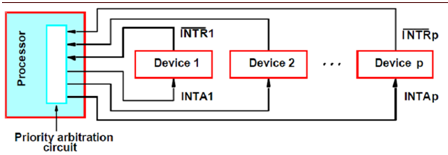
Implementation of interrupt priory by using individual interrupt-request and acknowledge lines
Polled interrupts: Priority decided by the order in which processor polls the component (polls their status registers) vectored interrupts: Priority determined by the order in which processor tells component toput its code on the address lines (order of connection in the chain)
|
Fig 5 – Polled interrupts
(a) Daisy chain
Daisy chaining of INTA: If device has not requested any service, passes the INTA signal to next device if necessitate service, does not pass the INTA, puts its code on the address lines Polled
|
Fig 6 – Daisy Chain
Key takeaways
- Continue to accept interrupt requests from higher priority components
- Disable interrupts from component at the same level priority or lower
- At the time of execution of interrupt-service routine
- Privileged instructions executed in the supervisor mode
Computer input-output units (in short computer I/O) include interface units (otherwise called interfaces or controllers) that directly co-operate with computer peripheral (external) devices. Interface units are connected to a processor by means of data, address and control bus. Processor's co-operation with I/O interface units consists in information exchange. To implement this co-operation, the processor performs input/output internal instructions, which determine read or write operation concerning selected memory devices (usually registers) existing in these interface units. On the other hand, I/O interfaces co-operate with peripheral devices. This co-operation consists in data transmissions between an external device and the memory devices in I/O interfaces, controlled by control signals exchange between these units. The control signal exchange usually follows a control protocol with handshaking. In this protocol, one of co-operating devices sends service request and the other responds by an acknowledge signal, which is a confirmation of a device readiness to perform an action or is a confirmation of an already performed action, for example a data read. A general schematic of interconnections between an I/O interface, a processor and an external device is shown in the figure below.
|
Fig 7 - Interconnections between an I/O interface a processor and an external device
Registers inside I/O interfaces, which are accessible for a processor, are called ports. To select a given external device (more precisely its interface), a processor uses its port address (i.e. an interface register address). The address can be a reserved address from the main memory address sub-space assigned for I/O interfaces addressing or it can be an address from a separate address space that has been specially created for I/O interfaces.
In the first case, we say that I/O interfaces are memory-mapped and that the main memory space is common for a processor and I/O interfaces. In this case, standard internal instructions - memory read and write are used but with reserved port addresses. In the second case, the processor has separate internal instructions (I/O read, I/O write) for accessing I/O interfaces, in which special I/O addresses are used.
With a common address space, special address decoders (selectors) capture the reserved I/O addresses and make that the addresses on the address bus are used not by the main memory but by I/O interfaces. To main memory, no read or write control signals are sent, instead, the control signals are sent to I/O interfaces. These signals are generated in special additional logic circuits. It is shown in the figure below.
|
Fig 8 - Control signal generation for memory-mapped I/O
In a computer, we have many I/O interfaces connected to the same system bus of a processor. The interfaces have to be able to request services from the processor, for example to request the processor to read data sent by an external device. There are three methods of co-operation between the I/O units and a processor:
- program-controlled method - by polling,
- interrupt-based method,
- Direct memory access- DMA-based method.
These methods will be discussed in next sections of this lecture.
Programmed control of I/O units
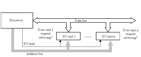
In the program- controlled method of processor co-operation with I/O units - by I/O interface polling, the I/O interface units are passive in respect to a processor, i.e. they do not send any control signals to the processor. The I/O interface units are equipped with status or request registers, which are ports inspected by the processor. An I/O unit, which requests servicing, leaves in its request register information on the kind of requested processor actions. If with the servicing some data are concerned, they are prepared in another register or a special kind of memory existing in the I/O unit. The processor, under control of the operating system or less frequently of a user program, can systematically read request registers in I/O units. For this purpose, the processor executes read I/O instructions with addresses pointing out the desired request registers in I/O interface units. This is shown in the figure below.
|
Fig 9 - Programmed control of I/O interface units (by polling)
As a result of these instructions, the register contents is fetched to the processor accumulator register to be subsequently decoded in a programmed way. As a result of the decoding, the polling control program discovers the kind of requested service and takes the respective actions. The programmed control method of I/O units is the least efficient. It is applied when there is no possibility to apply other faster methods or the I/O interface unit admits slow or very rare servicing.
Interrupt-based control of I/O units
It is the most frequently applied method for I/O interface unit control. With this method, the I/O unit that requests servicing sends an interrupt request signal to the processor. In response to the interrupt request, the processor performs the requested operations. Usually, several I/O units can send interrupt requests to a processor. The processor has one input pin for maskable interrupt and one input pin for non-maskable interrupt, which without any additional control hardware can be stimulated only at the basis of an OR-on-wire logical function. A problem arises of detection by the processor, which I/O units have sent interrupt signals and of selection of one of them for servicing, since the processor can service only one interrupt at a time.
There are known 3 basic methods for identification and selection of interrupting I/O units for servicing:
- identification by polling,
- daisy-chain identification,
- identification by vector interrupts.
Interrupt identification by polling
Interrupt identification by polling is organized in a similar way as programmed I/O units servicing.
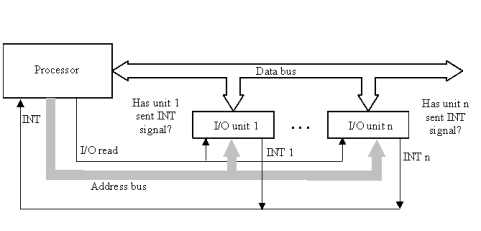
The unit, which has sent an interrupt request signal to the processor, leaves in a special register, available for the processor, information about sending the request and about the kind of service that is required. When a summary interrupt signal is detected by the processor (more exactly the operating system or another program for interrupt processing) programmed identification of the interrupt reason starts. For this, request registers are read one by one in I/O units until the first I/O unit is discovered, which has sent the interrupt. The schematic of this type of interrupt identification is shown in the figure below.
|
Fig 10 - Interrupt identification by polling
Depending on the applied strategy, after discovering the first interrupt reason its servicing can take place or further I/O unit polling after which selection takes place of the unit whose interrupt will be serviced. This type of interrupt identification is the slowest one and is applied when hardware interrupt identification cannot service all the interrupt reasons.
Interrupt identification by daisy-chain method
Daisy-chain interrupt identification method is partially hardware supported. Between subsequent I/O units that are set in a chain, transmission lines are installed that convey interrupt acknowledge - IACK signals sent by the processor when it receives an interrupt signal on its interrupt pin. The respective schematic is shown below.
|
Fig 11 - Daisy chain interrupt identification scheme
All the I/O units send interrupts on the same interrupt pin INT of a processor. After reception of the interrupt signal, the processor responds by the IACK acknowledge signal, which is received by the first I/O unit in the chain. If this is the unit that has sent the INT signal, it responds to the IACK signal by exposing on the data bus its identifier (it does it by opening the output of a special register that holds the identifier). Together with the identifier, additional information can be sent that better describes the interrupt reason. The processor reads in information from the data bus, decodes it in programmed way and activates the interrupt service program, appropriate for the identified I/O unit. Next, the processor removes the IACK signal. If the I/O unit 1 has not sent the INT signal, it sends the IACK signal to the next unit in the chain. This interrupt identification method is relatively fast and economic due to the small amount of additional hardware used. It is applied in simpler computer systems.
Vector interrupts identification
The most efficient and flexible interrupt identification method is a completely hardware method based on the use of interrupt vectors. With this method, a hardware interrupt controller is connected to the processor. It performs interrupt registration, selection and encoding. Its block diagram is shown below.
|
Fig 12 - Vector interrupt controller
Many independent interrupt lines are entering on the inputs of the controller, using which interrupt signals are coming from I/O units. Interrupt lines are assigned priorities according to a setting of the Priority set register, which is programmable by the processor. The interrupt controller enables a double selection control of interrupts that request servicing:
- by masking individual interrupt lines,
- by examining admissible priority level.
To support mask processing, the controller includes the mask register that is programmed by the processor. Masking consists in blocking interrupt storing in the interrupt request register, based on a mask set for particular interrupt lines in the Mask register. Among unmasked interrupt requests stored in the Interrupt register, the interrupt with the highest priority is selected. For this interrupt, the corresponding interrupt vector is generated, which constitutes the binary encoded priority level of this interrupt (no two interrupts have the same priority level). This is performed by the interrupt detect and encode unit. The vector of the highest priority interrupt is next compared in the comparator unit with the minimal priority level admissible for servicing. This level is set by the processor as well. If the most priority current interrupt has the priority not lower than the admissible priority level, the interrupt signal INT is generated and sent to the processor interrupt input pin. In response to this signal, the processor sends back the IACK - interrupt acknowledge signal to the controller. Next, the controller introduces the interrupt vector onto the data bus. This vector is read by the processor into its index address register. This register is next used for indexing (arithmetic modification) of the basic interrupt subroutine address while calling the subroutine, which is responsible for servicing the respective selected, interrupt controller input line.
The vector interrupt identification method is commonly used in contemporary computer systems.
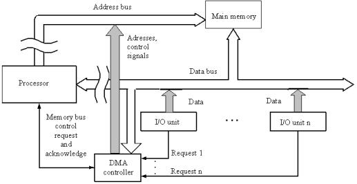
The last method for organizing processor co-operation with I/O units is based on the use of Direct Memory Access - DMA controllers. A DMA controller enables data reads and writes from/to main memory form the side of I/O interface units without the direct control or intermediate role of the processor. With such a method, external devices can autonomously co-operate with the memory without taking processor time.
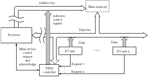
Knowing the main memory addresses used in DMA transmissions to or from I/O devices, the processor can read or write in the main memory data relevant in co-operation with these devices. The DMA unit is a controller to which I/O devices are connected for direct communication with the main memory. The DMA controller, on request coming from an external device, requests from the processor liberating of the busses going to the main memory. When the processor fulfills the request, the DMA controller takes the control over the main memory. It sends addresses and control signals to the memory, necessary for the transmission with the external device. As a result, data are directly exchanged between the external device and the main memory. The basic concept of this type of co-operation is shown in the figure below.
|
Fig 13 - Co-operation of a processor with I/O units via a DMA controller
DMA controllers are programmed by processors, which set all transmission parameters for I/O devices in appropriate control registers contained in these controllers. Usually there are several transmission channels in a DMA controller that can be used for co-operation with different I/O external devices.
Co-operation with I/O units via DMA controllers is frequently used in organizing processor's communication with peripheral memories such as hard disks or optical disks.
Key takeaways
- Computer input-output units (in short computer I/O) include interface units (otherwise called interfaces or controllers) that directly co-operate with computer peripheral (external) devices. Interface units are connected to a processor by means of data, address and control bus. Processor's co-operation with I/O interface units consists in information exchange. To implement this co-operation, the processor performs input/output internal instructions, which determine read or write operation concerning selected memory devices (usually registers) existing in these interface units.
Exceptions and interrupts are unexpected events which will disrupt the normal flow of execution of instruction (that is currently executing by processor). An exception is an unexpected event from within the processor. Interrupt is an unexpected event from outside the process.
Whenever an exception or interrupt occurs, the hardware starts executing the code that performs an action in response to the exception. This action may involve killing a process, outputting an error message, communicating with an external device, or horribly crashing the entire computer system by initiating a “Blue Screen of Death” and halting the CPU. The instructions responsible for this action reside in the operating system kernel, and the code that performs this action is called the interrupt handler code. Now, We can think of handler code as an operating system subroutine. Then, After the handler code is executed, it may be possible to continue execution after the instruction where the execution or interrupt occurred.
Exception and Interrupt Handling:
Whenever an exception or interrupt occurs, execution transition from user mode to kernel mode where the exception or interrupt is handled. In detail, the following steps must be taken to handle an exception or interrupts.
While entering the kernel, the context (values of all CPU registers) of the currently executing process must first be saved to memory. The kernel is now ready to handle the exception/interrupt.
- Determine the cause of the exception/interrupt.
- Handle the exception/interrupt.
When the exception/interrupt have been handled the kernel performs the following steps:
- Select a process to restore and resume.
- Restore the context of the selected process.
- Resume execution of the selected process.
At any point in time, the values of all the registers in the CPU defines the context of the CPU. Another name used for CPU context is CPU state.
The exception/interrupt handler uses the same CPU as the currently executing process. When entering the exception/interrupt handler, the values in all CPU registers to be used by the exception/interrupt handler must be saved to memory. The saved register values can later restored before resuming execution of the process.
The handler may have been invoked for a number of reasons. The handler thus needs to determine the cause of the exception or interrupt. Information about what caused the exception or interrupt can be stored in dedicated registers or at predefined addresses in memory.
Next, the exception or interrupt needs to be serviced. For instance, if it was a keyboard interrupt, then the key code of the key press is obtained and stored somewhere or some other appropriate action is taken. If it was an arithmetic overflow exception, an error message may be printed or the program may be terminated.
The exception/interrupt have now been handled and the kernel. The kernel may choose to resume the same process that was executing prior to handling the exception/interrupt or resume execution of any other process currently in memory.
The context of the CPU can now be restored for the chosen process by reading and restoring all register values from memory.
The process selected to be resumed must be resumed at the same point it was stopped. The address of this instruction was saved by the machine when the interrupt occurred, so it is simply a matter of getting this address and make the CPU continue to execute at this address.
Key takeaways
- Exceptions and interrupts are unexpected events which will disrupt the normal flow of execution of instruction (that is currently executing by processor). An exception is an unexpected event from within the processor. Interrupt is an unexpected event from outside the process.
- Whenever an exception or interrupt occurs, the hardware starts executing the code that performs an action in response to the exception. This action may involve killing a process, outputting an error message, communicating with an external device, or horribly crashing the entire computer system by initiating a “Blue Screen of Death” and halting the CPU.
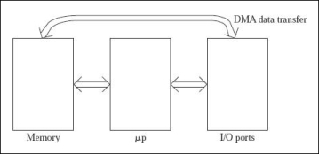
The microcomputer system basically consists of three blocks
- The microprocessor
- The memories of microprocessor like EPROM and RAM
- The I/O ports by which they are connected.
The possible data transfers are indicated below.
- Between the memory and microprocessor data transfer occurs by using the LDA and STA instructions.
- Between microprocessor and I/O ports also data transfer occurs by the help of two instructions IN and OUT.
- Through DMA data transfer, data is transferred between the Input Output ports and the memory.
|
Fig 14 - The figure shows possible ways of data transfers in a microcomputer system.
For performing the data transfer either between the microprocessor and memory or between I/O ports and the processor instructions for the programs are executed such that, the data transfers which are called as programmed data transfer, are already in used when a small amount of data transfer is involved in the process.
Both the microprocessor and the memory are made of semiconductor chips that work in comparable to electronic speeds. So it is not all a problem to transfer the data between microprocessor and memory. If the case arises such that the memory is slow than the microprocessor, the processor used has to insert wait states. No problem other than this can occur.
The ports like 8255, 8212 and others are also made by semiconductor chips which work at electronic speeds. We use them for interfacing the INPUT–OUTPUT devices which are electromechanical in nature, and hence the speed of the microprocessor turns slower which results the transfer of data between microprocessor and INPUT-OUTPUT ports becomes very complex in nature.
If the data transfer which is used for reading from the memory location is 3456H and then writing to output port number is 50H which takes 13 clocks only for reading from memory location 3456H using the LDA 3456H instruction and ten clocks for writing to the output port number 50H. Therefore 23 clocks in total. If the processor works at an internal frequency of 3-MHz with a clock period of 0.33μs, it takes a fraction of 7.66μs to work externally. By using the program data transfer scheme, input port 40H is read and written to the memory location input port 2345H
If we use DMA data transfer to read from memory location 3456H and write to the output port number 50H only four clocks are needed, which results a fraction of only 1.33μs. Some devices like hard disk and floppy disk can perform data transfer at a very fast speed. A floppy disk of memory 1.44 MB which rotates at a speed of 360 rpm, having 18 sectors per track, can store up to 512 bytes of memory, when the rate of data transfer becomes 54K bytes in a second, or about 19μs per byte. Hard disks can easily transfer data at least ten times faster. Hence it turns out to be 1.9μs per byte. This is the situation when DMA data transfer becomes compulsory. In the programmed data transfer process where we need 7.66μs per byte only the 4 bytes comes out from the hard disk in the same time repeatedly. Hence it can be concluded that I/O devices plays an important role in the DMA data transfer process.
To obtain statistics like average, the largest, and the smallest values, we use Analog to Digital converter. Using the programmed data transfer scheme 1,000 × 7.66 = 7,660μs of processor time is needed. But surprisingly using the DMA data transfer scheme only 1,000 × 1.33 = 1,330μs of time is needed. So when large amount of data is to be transferred between the memory and I/O port by routing each byte through microprocessor, it takes a lot of time, so to do the work in less time the I/O port can be directly accessed to the memory for data transfer. This scheme is termed as DMA data transfer.
Key takeaways
- The microcomputer system basically consists of three blocks
- The microprocessor
- The memories of microprocessor like EPROM and RAM
- The I/O ports by which they are connected.
A bus is a communication system in computer architecture that transfers data between components inside a computer, or between computers.
The term encompasses all the components related to hardware (wire, optical fibre, etc.) and software, including communication protocol.
The following are a few points to describe a computer bus:
- A bus is a group of lines/wires which carry computer signals.
- A bus is the means of shared transmission.
- Lines are assigned for providing descriptive names. — carries a single electrical signal, e.g. 1-bit memory address, data bits series, or timing control that turns the device on or off.
- Data can be transferred from one computer system location to another (between different I / O modules, memory, and CPU).
- The bus is not only cable but also hardware (bus architecture), protocol, program, and bus controller.
What are the different components of a bus?
Each bus possesses three distinct communication channels.
Following are the three components of a bus: –
- The address bus, a one-way pathway that allows information to pass in one direction only, carries information about where data is stored in memory.
- The data bus is a two-way pathway carrying the actual data (information) to and from the main memory.
- The control bus holds the control and timing signals needed to coordinate all of the computer’s activities.
Functions of a computer bus
Below are a few of the functions in a computer bus:
- Data sharing – All types of buses used in network transfer data between the connected computer peripherals. The buses either transfer or send data in serial or parallel transfer method. This allows 1, 2, 4, or even 8 bytes of data to be exchanged at a time. (A Byte is an 8-bit group). Buses are classified according to how many bits they can move simultaneously, meaning we have 8-bit, 16-bit, 32-bit, or even 64-bit buses.
- Addressing – A bus has address lines that suit the processors. This allows us to transfer data to or from different locations in the memory.
- Power – A bus supplies the power to various connected peripherals.
Structure and Topologies of Computer buses
Lines are grouped as mentioned below –
- Power line provides electrical power to the components connected
- Data lines carrying data or instructions between modules of the system
- Address lines indicate the recipient of the bus data
- Control lines control the synchronization and operation of the bus and the modules linked to the bus
What are the different types of computer buses?
Computers normally have two bus types:
- System bus – This is the bus that connects the CPU to the motherboard’s main memory. The system bus is also known as a front-side bus, a memory bus, a local bus, or a host bus.
- A number of I / O Buses, (I / O is an input/output acronym) connecting various peripheral devices to the CPU. These devices connect to the system bus through a ‘bridge’ implemented on the chipset of the processors. Other I / O bus names include “expansion bus,” “external bus” or “host bus”
Below are some of the types of Expansion buses:
ISA – Industry Standard Architecture
The Industry Standard Architecture (ISA) bus is still one of the oldest buses in service today.
Although it has been replaced by faster buses, ISA still has a lot of legacy devices that connect to it such as cash registers, CNC machines, and barcode scanners. Since being expanded to 16 bits in 1984, ISA remains largely unchanged. Additional high-speed buses were added to avoid performance problems.
EISA – Extended Industry Standard Architecture
An upgrade to ISA is Extended Industry Standard Architecture or EISA. This doubled the data channels from 16 to 32 and allowed the bus to be used by more than one CPU. Although deeper than the ISA slot, it is the same width that lets older devices connect to it.
When you compare the pins on an ISA to an EISA card (the gold portion of the card that goes into the slot), you can find that the EISA pins are longer and thinner. That is a quick way to decide if you have an ISA or an EISA card.
MCA – Micro Channel Architecture
IBM developed this bus as a substitute for ISA when they designed the PS/2 PC which was launched in 1987. The bus provided some technological improvements over the ISA bus. The MCA, for example, ran at a speed of 10MHz faster and supported either 16-bit or 32-bit data.
One advantage of MCA was that the plug-in cards were configurable software; that means they needed minimal user input during configuration.
VESA – Video Electronics Standards Association
The Video Electronics Standards Association (VESA) Local bus was created to divide the load and allow the ISA bus to handle interrupts, and the I / O port (input/output) and the VL bus to work with Direct Memory Access (DMA) and I / O memory. This was only a temporary solution, due to its size and other considerations. The PCI bus was easy to overtake the VL bus.
A VESA card has a range of additional pins and is longer than the ISA or EISA cards. It was created in the early ’90s and has a 32-bit bus and was a temporary fix designed to help boost ISA ‘s performance.
PCI – Peripheral Component Interconnect
The PCI bus was developed to solve ISA and VL-bus related issues. PCI has a 32-bit data path and will run at half the speed of the system memory bus.
One of its enhancements was to provide connected computers with direct access to machine memory. That increased computer efficiency while reducing the CPU ‘s capacity for interference.
Today’s computers mostly have PCI slots. PCI is considered a hybrid between ISA and VL-Bus that provides direct access to the connected devices system memory.
This uses a bridge to connect to the front side bus and CPU and is able to provide higher performance while reducing the potential for CPU interference.
The most recent added slot is PCI Express (PCIe). It was designed to replace the AGP and PCI bus. It has a 64-bit data path and 133 MHz base speed but incorporating full-duplex architecture was the main performance enhancement.
That allowed the card to run in both directions at full speed simultaneously. PCI Express slots run at 1X, 4X, 8X, and 16X providing PCI with the highest transfer speed of any form of a slot. The multiplier specifies the maximum rate of transfer.
PCI Express is compatible backward, allowing a 1X card to fit into a 16X slot.
PCMCIA – Personal Computer Memory Card Industry Association (Also called PC bus)
The Personal Computer Memory Card Industry Association was established to give the laptop computers a standard bus. But it is used in small computers, essentially.
AGP – Accelerated Graphics Port
The Accelerated Graphics Bus (AGP) was designed to accommodate the computers’ increased graphics needs. It has a data path that is 32 bits long and runs at maximum bus speed.
This doubled the PCI bandwidth and reduced the need to share the bus with other components. This means that AGP operates at 66 MHz on a regular motherboard, instead of the 33 MHz of the PCI bus.
AGP has a base speed of 66 MHz that doubles PCI speed. You can also get slots that run at speeds 2X, 4X, and 8X.
It also uses special signalling to allow twice as much data to be transmitted at the same clock speed over the port.
SCSI – Small Computer Systems Interface.
Small Computer System Interface is a standard parallel interface used for attaching peripheral devices to a computer by Apple Macintosh computers, PCs, and Unix systems.
Most common types of computer buses
Most of the listed buses are no longer used or not frequently used today.
Below is a list of the buses that are the most popular ones:
- ESATA and SATA– Hard Drives and Disk Drives computer.
- PCIe – Video Cards and Computer Expansion Cards.
- USB – Peripherals to a computer.
- Thunderbolt – Peripherals that are connected via a USB-C cable.
Key takeaways
- A bus is a communication system in computer architecture that transfers data between components inside a computer, or between computers.
- The term encompasses all the components related to hardware (wire, optical fibre, etc.) and software, including communication protocol.
References
1. William Stallings: Computer Organization & Architecture, 7th Edition, PHI, 2006.
2. Vincent P. Heuring & Harry F. Jordan: Computer Systems Design and Architecture, 2 nd Edition, Pearson Education, 2004.
