In this chapter, let us discuss about the basic arithmetic operations, which can be performed on any two signed binary numbers using 2’s complement method. The basic arithmetic operations are addition and subtraction.
Addition of two Signed Binary Numbers
Consider the two signed binary numbers A & B, which are represented in 2’s complement form. We can perform the addition of these two numbers, which is similar to the addition of two unsigned binary numbers. But, if the resultant sum contains carry out from sign bit, then discard ignore it in order to get the correct value.
If resultant sum is positive, you can find the magnitude of it directly. But, if the resultant sum is negative, then take 2’s complement of it in order to get the magnitude.
Let us perform the addition of two decimal numbers +7 and +4 using 2’s complement method.
The 2’s complement representations of +7 and +4 with 5 bits each are shown below.
+7 10 = 00111 2 +4 10 = 00100 2 The addition of these two numbers is +7 10 ++410 = 001112+00100 2 ⇒+7 10 ++410 = 01011 2. |
The resultant sum contains 5 bits. So, there is no carry out from sign bit. The sign bit ‘0’ indicates that the resultant sum is positive. So, the magnitude of sum is 11 in decimal number system. Therefore, addition of two positive numbers will give another positive number.
Let us perform the addition of two decimal numbers -7 and -4 using 2’s complement method.
The 2’s complement representation of -7 and -4 with 5 bits each are shown below.
−7 10 = 11001 2 −4 10 = 11100 2 The addition of these two numbers is −7 10 + −410 = 110012 + 11100 2 ⇒−7 10 + −410 = 110101 2. |
The resultant sum contains 6 bits. In this case, carry is obtained from sign bit. So, we can remove it
Resultant sum after removing carry is −7 10 + −410 = 10101 2. |
The sign bit ‘1’ indicates that the resultant sum is negative. So, by taking 2’s complement of it we will get the magnitude of resultant sum as 11 in decimal number system. Therefore, addition of two negative numbers will give another negative number.
Subtraction of two Signed Binary Numbers
Consider the two signed binary numbers A & B, which are represented in 2’s complement form. We know that 2’s complement of positive number gives a negative number. So, whenever we have to subtract a number B from number A, then take 2’s complement of B and add it to A. So, mathematically we can write it as
A - B = A + 2′scomplementofB
Similarly, if we have to subtract the number A from number B, then take 2’s complement of A and add it to B. So, mathematically we can write it as
B - A = B + 2′scomplementofA
So, the subtraction of two signed binary numbers is similar to the addition of two signed binary numbers. But, we have to take 2’s complement of the number, which is supposed to be subtracted. This is the advantage of 2’s complement technique. Follow, the same rules of addition of two signed binary numbers.
Let us perform the subtraction of two decimal numbers +7 and +4 using 2’s complement method.
The subtraction of these two numbers is
+7
10 − +410 = +710 + −4
10.
The 2’s complement representation of +7 and -4 with 5 bits each are shown below.
+7 10 = 00111 2 +4 10 = 11100 2 ⇒+7 10 + +410 = 001112 + 111002 = 00011 2 |
Here, the carry obtained from sign bit. So, we can remove it. The resultant sum after removing carry is
+7
10 + +410 = 00011
2
The sign bit ‘0’ indicates that the resultant sum is positive. So, the magnitude of it is 3 in decimal number system. Therefore, subtraction of two decimal numbers +7 and +4 is +3.
Let us perform the subtraction of two decimal numbers +4 and +7 using 2’s complement method.
The subtraction of these two numbers is
+4
10 − +710 = +410 + −7
10.
The 2’s complement representation of +4 and -7 with 5 bits each are shown below.
+4 10 = 00100 2 −7 10 = 11001 2 ⇒+4 10 + −710 = 001002 + 110012 = 11101 2 |
Here, carry is not obtained from sign bit. The sign bit ‘1’ indicates that the resultant sum is negative. So, by taking 2’s complement of it we will get the magnitude of resultant sum as 3 in decimal number system. Therefore, subtraction of two decimal numbers +4 and +7 is -3.
Key takeaways
- Addition of two Signed Binary Numbers: Consider the two signed binary numbers A & B, which are represented in 2’s complement form. We can perform the addition of these two numbers, which is similar to the addition of two unsigned binary numbers. But, if the resultant sum contains carry out from sign bit, then discard ignore it in order to get the correct value.
- If resultant sum is positive, you can find the magnitude of it directly. But, if the resultant sum is negative, then take 2’s complement of it in order to get the magnitude.
- We have done what is called a ripple carry adder.
- The carry ripples'' from one bit to the next (LOB to HOB).
- So, the time required is proportional to the word length
- Each carry can be computed with two levels of logic (any function can be so computed) hence the number of gate delays for an n bit adder is 2n.
- For a 4-bit adder 8 gate delays are required.
- For an 16-bit adder 32 gate delays are required.
- For an 32-bit adder 64 gate delays are required.
- For an 64-bit adder 128 gate delays are required.
- What about doing the entire 32 (or 64) bit adder with 2 levels of logic?
- Such a circuit clearly exists. Why?
Ans: A two levels of logic circuit exists for any function. - But it would be very expensive: many gates and wires.
- The big problem: When expressed with two levels of login, the AND and OR gates have high fan-in, i.e., they have a large number of inputs. It is not true that a 64-input AND takes the same time as a 2-input AND.
- Unless you are doing full custom VLSI, you get a toolbox of primative functions (say 4 input NAND) and must build from that
- Such a circuit clearly exists. Why?
- There are faster adders, e.g. carry lookahead and carry save. We will study carry lookahead adders.
Carry Lookahead Adder (CLA)
This adder is much faster than the ripple adder we did before, especially for wide (i.e., many bit) addition.
- For each bit position we have two input bits, a and b (really should say ai and bi as I will do below).
- We can, in one gate delay, calculate two other bits called generate g and propagate p, defined as follows:
- The idea for propagate is that p is true if the current bit will propagate a carry from its input to its output.
- It is easy to see that p = (a OR b), i.e.
if and only if (a OR b)
then if there is a carry in
then there is a carry out - The idea for generate is that g is true if the current bit will generate a carry out (independent of the carry in).
- It is easy to see that g = (a AND b), i.e.
if and only if (a AND b)
then the must be a carry-out independent of the carry-in
To summarize, using a subscript i to represent the bit number,
to generate a carry: gi = ai bi
to propagate a carry: pi = ai+bi
H&P give a plumbing analogue for generate and propagate.
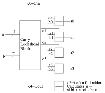
Given the generates and propagates, we can calculate all the carries for a 4-bit addition (recall that c0=Cin is an input) as follows (this is the formula version of the plumbing):
c1 = g0 + p0 c0
c2 = g1 + p1 c1 = g1 + p1 g0 + p1 p0 c0
c3 = g2 + p2 c2 = g2 + p2 g1 + p2 p1 g0 + p2 p1 p0 c0
c4 = g3 + p3 c3 = g3 + p3 g2 + p3 p2 g1 + p3 p2 p1 g0 + p3 p2 p1 p0 c0 |
Thus, we can calculate c1 ... c4 in just two additional gate delays (where we assume one gate can accept up to 5 inputs). Since we get gi and pi after one gate delay, the total delay for calculating all the carries is 3 (this includes c4=Carry-Out)
Each bit of the sum si can be calculated in 2 gate delays given ai, bi, and ci. Thus, for 4-bit addition, 5 gate delays after we are given a, b and Carry-In, we have calculated s and Carry-Out.
|
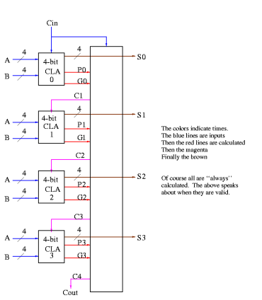
Fig 1 - Example
So, for 4-bit addition, the faster adder takes time 5 and the slower adder time 8.
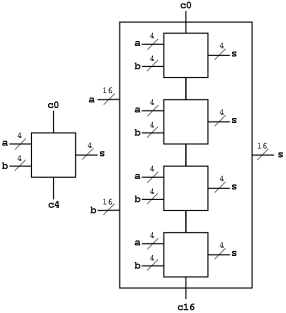
Now we want to put four of these together to get a fast 16-bit adder.
As black boxes, both ripple-carry adders and carry-lookahead adders (CLAs) look the same.
We could simply put four CLAs together and let the Carry-Out from one be the Carry-In of the next. That is, we could put these CLAs together in a ripple-carry manner to get a hybrid 16-bit adder.
- Since the Carry-Out is calculated in 3 gate delays, the Carry-In to the high order 4-bit adder is calculated in 3*3=9 delays.
- Hence the overall Carry-Out takes time 9+3=12 and the high order four bits of the sum take 9+5=14. The other bits take less time.
- So, this mixed 16-bit adder takes 14 gate delays compared with 2*16=32 for a straight ripple-carry 16-bit adder.
We want to do better so we will put the 4-bit carry-lookahead adders together in a carry-lookahead manner. Thus, the diagram above is not what we are going to do.
- We have 33 inputs a0,...,a15; b0,...b15; c0=Carry-In
- We want 17 outputs s0,...,s15; c16=c=Carry-Out
- Again, we are assuming a gate can accept upto 5 inputs.
- It is important that the number of inputs per gate does not grow with the number of bits in each number.
- If the technology available supplies only 4-input gates (instead of the 5-input gates we are assuming), we would use groups of three bits rather than four
We start by determining super generate'' and super propagate'' bits.
- The super generate indicates whether the 4-bit adder constructed above generates a Carry-Out.
- The super propagate indicates whether the 4-bit adder constructed above propagates a Carry-In to a Carry-Out.
P0 = p3 p2 p1 p0 Does the low order 4-bit adder propagate a carry? P1 = p7 p6 p5 p4 P2 = p11 p10 p9 p8 P3 = p15 p14 p13 p12 Does the high order 4-bit adder propagate a carry? G0 = g3 + p3 g2 + p3 p2 g1 + p3 p2 p1 g0 Does low order 4-bit adder generate a carry G1 = g7 + p7 g6 + p7 p6 g5 + p7 p6 p5 g4 G2 = g11 + p11 g10 + p11 p10 g9 + p11 p10 p9 g8 G3 = g15 + p15 g14 + p15 p14 g13 + p15 p14 p13 g12 |
From these super generates and super propagates, we can calculate the super carries, i.e. the carries for the four 4-bit adders.
- The first super carry C0, the Carry-In to the low-order 4-bit adder, is just c0 the input Carry-In.
- The second super carry C1 is the Carry-Out of the low-order 4-bit adder (which is also the Carry-In to the 2nd 4-bit adder.
- The last super carry C4 is the Carry-out of the high-order 4-bit adder (which is also the overall Carry-out of the entire 16-bit adder).
C1 = G0 + P0 c0
C2 = G1 + P1 C1 = G1 + P1 G0 + P1 P0 c0
C3 = G2 + P2 C2 = G2 + P2 G1 + P2 P1 G0 + P2 P1 P0 c0
C4 = G3 + P3 C3 = G3 + P3 G2 + P3 P2 G1 + P3 P2 P1 G0 + P3 P2 P1 P0 c0 |
Now these C's (together with the original inputs a and b) are just what the 4-bit CLAs need.
How long does this take, again assuming 5 input gates?
- We calculate the p's and g's (lower case) in 1 gate delay (as with the 4-bit CLA).
- We calculate the P's one gate delay after we have the p's or 2 gate delays after we start.
- The G's are determined 2 gate delays after we have the g's and p's. So the G's are done 3 gate delays after we start.
- The C's are determined 2 gate delays after the P's and G's. So the C's are done 5 gate delays after we start.
- Now the C's are sent back to the 4-bit CLAs, which have already calculated the p's and g's. The C's are calculated in 2 more gate delays (7 total) and the s's 2 more after that (9 total).
In summary, a 16-bit CLA takes 9 cycles instead of 32 for a ripple carry adder and 14 for the mixed adder.
|
Some pictures follow.
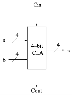
Take our original picture of the 4-bit CLA and collapse the details so it looks like.
|
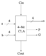
Next include the logic to calculate P and G.
Now put four of these with a CLA block (to calculate C's from P's, G's and Cin) and we get a 16-bit CLA. Note that we do not use the Cout from the 4-bit CLAs.
|
Fig 2 - Example
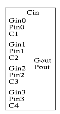
Note that the tall skinny box is general. It takes 4 Ps 4Gs and Cin and calculates 4Cs. The Ps can be propagates, superpropagates, superduperpropagates, etc. That is, you take 4 of these 16-bit CLAs and the same tall skinny box and you get a 64-bit CLA.
Homework: 4.44, 4.45
As noted just above the tall skinny box is useful for all size CLAs. To expand on that point and to review CLAs, let's redo CLAs with the general box.
Since we are doing 4-bits at a time, the box takes 9=2*4+1 input bits and produces 6=4+2 outputs
- Inputs
- 4 generate bits from the previous size (i.e. if now doing a 64-bit CLA, these are the generate bits from the four 16-bit CLAs). Let's call these bits Gin0, Gin1, Gin2, Gin3.
- 4 propagate bits from the previous size Pin0, Pin1, Pin2, Pin3.
- The Carry in Cin
- Outputs
- Four carries C1, C2, C3, and C4 to be used in the previous size
- Cin is also called C0 and is used in the previous size as well as in this box.
- C4 is also called Cout. It is the carry out from this size, but is not used in the next size
- Gout and Pout, the generate and propagate to be used in the next size
- Four carries C1, C2, C3, and C4 to be used in the previous size
C1 = G0 + PO Cin C2 = G1 + P1 G0 + P1 P0 Cin C3 = G2 + P2 G1 + P2 P1 G0 + P2 P1 P0 Cin C4 = G3 + P3 G2 + P3 P2 G1 + P3 P2 P1 G0 + P3 P2 P1 P0 Cin
Gout = G3 + P3 G2 + P3 P2 G1 + P3 P2 P1 Go Pout = P3 P2 P1 P0
|
Picture
|
Fig 3 – Example
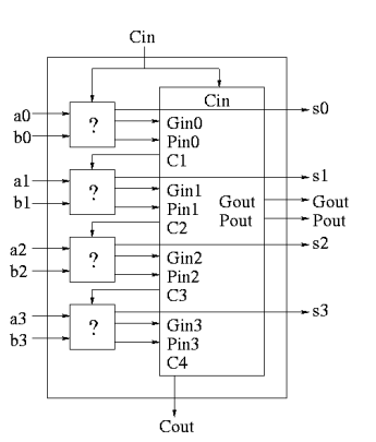
A 4-bit adder is now
|
Fig 4 - 4-bit adder
What does the ?'' box do?
|
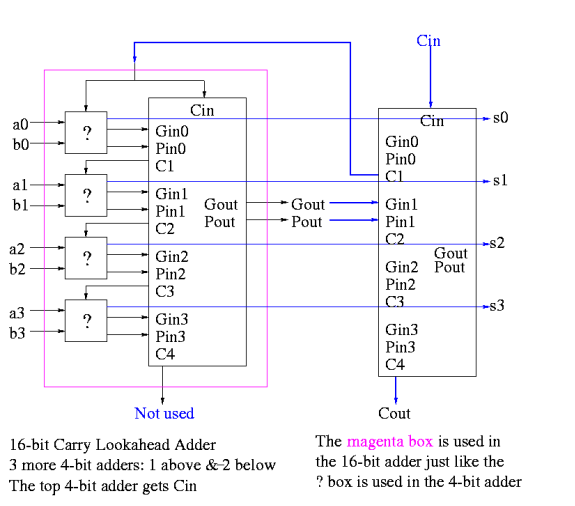
Now take four of these 4-bit adders and use the identical CLA box to get a 16-bit adder
|
Fig 5 - Example
Four of these 16-bit adders with the identical CLA box to gives a 64-bit adder.
Key takeaways
- We have done what is called a ripple carry adder.
- The carry ripples'' from one bit to the next (LOB to HOB).
So the time required is proportional to the wordlength
3. Each carry can be computed with two levels of logic (any function can be so computed) hence the number of gate delays for an n bit adder is 2n.
4. For a 4-bit adder 8 gate delays are required.
5. For an 16-bit adder 32 gate delays are required.
6. For an 32-bit adder 64 gate delays are required.
7. For an 64-bit adder 128 gate delays are required.
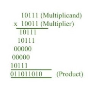
Multiplication of two fixed point binary number in signed magnitude representation is done with process of successive shift and add operation.
|
In the multiplication process we are considering successive bits of the multiplier, least significant bit first. If the multiplier bit is 1, the multiplicand is copied down else 0’s are copied down.
The numbers copied down in successive lines are shifted one position to the left from the previous number. Finally, numbers are added and their sum form the product.
The sign of the product is determined from the sign of the multiplicand and multiplier. If they are alike, sign of the product is positive else negative.
Hardware Implementation:
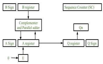
Following components are required for the Hardware Implementation of multiplication algorithm:
|
Fig 6 – Hardware implementation
- Registers:
Two Registers B and Q are used to store multiplicand and multiplier respectively.
Register A is used to store partial product during multiplication.
Sequence Counter register (SC) is used to store number of bits in the multiplier. - Flip Flop:
To store sign bit of registers we require three flip flops (A sign, B sign and Q sign).
Flip flop E is used to store carry bit generated during partial product addition.
3. Complement and Parallel adder:
This hardware unit is used in calculating partial product i.e, perform addition required.
Flowchart of Multiplication:
|
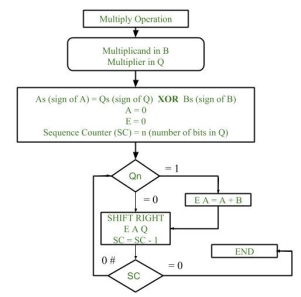
Fig 7 – Flow chart of multiplication
- Initially multiplicand is stored in B register and multiplier is stored in Q register.
- Sign of registers B (Bs) and Q (Qs) are compared using XOR functionality (i.e., if both the signs are alike, output of XOR operation is 0 unless 1) and output stored in As (sign of A register).
Note: Initially 0 is assigned to register A and E flip flop. Sequence counter is initialized with value n, n is the number of bits in the Multiplier.
3. Now least significant bit of multiplier is checked. If it is 1 add the content of register A with Multiplicand (register B) and result is assigned in A register with carry bit in flip flop E. Content of E A Q is shifted to right by one position, i.e., content of E is shifted to most significant bit (MSB) of A and least significant bit of A is shifted to most significant bit of Q.
4. If Qn = 0, only shift right operation on content of E A Q is performed in a similar fashion.
5. Content of Sequence counter is decremented by 1.
6. Check the content of Sequence counter (SC), if it is 0, end the process and the final product is present in register A and Q, else repeat the process.
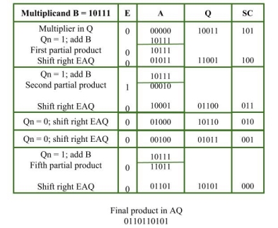
Example:
Multiplicand = 10111
Multiplier = 10011
|
Key takeaways
- Multiplication of two fixed point binary number in signed magnitude representation is done with process of successive shift and add operation.
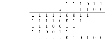
The following example shows signed 2's complement representation can be used to represent negative operands as well as positive ones in multiplication.
Example: 
|
Use n=6 bits to represent the product.
We first represent both operands in signed 2's complement, and then carry out the normal multiplication:
|
The last 6 bits of the result are  , representing a positive product
  .
.
Note:
- Both positive and negative operands should be properly sign extended whenever needed.
- When the multiplier is negative represented in signed 2's complement, each 1 added in front due to the sign extension requires an addition of the multiplicand to the partial product. However, one only needs to consider enough bits to guarantee n bits required in the result.
As shown in a problem, this method works in all cases of both positive and negative multiplicands and multipliers.
Key takeaways
- The following example shows signed 2's complement representation can be used to represent negative operands as well as positive ones in multiplication.
Example: 
|
2. Use n=6 bits to represent the product.
Booth’s algorithm is a multiplication algorithm that multiplies two signed binary numbers in 2’s compliment notation. Booth used desk calculators that were faster at shifting than adding and created the algorithm to increase their speed. Booth’s algorithm is of interest in the study of computer architecture. Here’s the implementation of the algorithm.
Input: 0110, 0010 Output: qn q[n+1] AC QR sc(step count) initial 0000 0010 4 0 0 rightShift 0000 0001 3 1 0 A = A - BR 1010 rightShift 1101 0000 2 0 1 A = A + BR 0011 rightShift 0001 1000 1 0 0 rightShift 0000 1100 0
Result=1100 |
Algorithm:
Put multiplicand in BR and multiplier in QR
and then the algorithm works as per the following conditions:
1. If Qn and Qn+1 are same i.e. 00 or 11 perform arithmetic shift by 1 bit.
2. If Qn Qn+1 = 10 do A= A + BR and perform arithmetic shift by 1 bit.
3. If Qn Qn+1= 01 do A= A – BR and perform arithmetic shift by 1 bit.
qn q[n + 1] BR AC QR sc initial 0000 1010 4 0 0 rightShift 0000 0101 3 1 0 A = A - BR 1010 rightShift 1101 0010 2 0 1 A = A + BR 0011 rightShift 0001 1001 1 1 0 A = A - BR 1011 rightShift 1101 1100 0
Result = 1100 |
Key takeaways
- Booth’s algorithm is a multiplication algorithm that multiplies two signed binary numbers in 2’s compliment notation. Booth used desk calculators that were faster at shifting than adding and created the algorithm to increase their speed. Booth’s algorithm is of interest in the study of computer architecture. Here’s the implementation of the algorithm.
A division algorithm provides a quotient and a remainder when we divide two number. They are generally of two type slow algorithm and fast algorithm. Slow division algorithm are restoring, non-restoring, non-performing restoring, SRT algorithm and under fast comes Newton–Raphson and Goldschmidt.
In this article, will be performing restoring algorithm for unsigned integer. Restoring term is due to fact that value of register A is restored after each iteration.
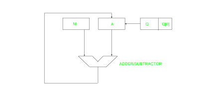
|
Fig 8 – Adder Subtractor
Here, register Q contain quotient and register A contain remainder. Here, n-bit dividend is loaded in Q and divisor is loaded in M. Value of Register is initially kept 0 and this is the register whose value is restored during iteration due to which it is named Restoring.
|
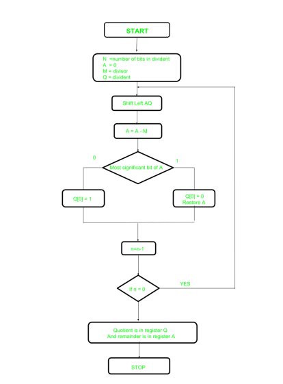
Fig 9 – Flowchart
Let’s pick the step involved:
- Step-1: First the registers are initialized with corresponding values (Q = Dividend, M = Divisor, A = 0, n = number of bits in dividend)
- Step-2: Then the content of register A and Q is shifted left as if they are a single unit
- Step-3: Then content of register M is subtracted from A and result is stored in A
- Step-4: Then the most significant bit of the A is checked if it is 0 the least significant bit of Q is set to 1 otherwise if it is 1 the least significant bit of Q is set to 0 and value of register A is restored i.e the value of A before the subtraction with M
- Step-5: The value of counter n is decremented
- Step-6: If the value of n becomes zero we get of the loop otherwise we repeat from step 2
- Step-7: Finally, the register Q contain the quotient and A contain remainder
Examples:
Perform Division Restoring Algorithm
Dividend = 11
Divisor = 3
n | M | A | Q | Operation |
4 | 00011 | 00000 | 1011 | Initialize |
| 00011 | 00001 | 011_ | shift left AQ |
| 00011 | 11110 | 011_ | A=A-M |
| 00011 | 00001 | 0110 | Q[0]=0 And restore A |
3 | 00011 | 00010 | 110_ | shift left AQ |
| 00011 | 11111 | 110_ | A=A-M |
| 00011 | 00010 | 1100 | Q[0]=0 |
2 | 00011 | 00101 | 100_ | shift left AQ |
| 00011 | 00010 | 100_ | A=A-M |
| 00011 | 00010 | 1001 | Q[0]=1 |
1 | 00011 | 00101 | 001_ | shift left AQ |
| 00011 | 00010 | 001_ | A=A-M |
| 00011 | 00010 | 0011 | Q[0]=1 |
Remember to restore the value of A most significant bit of A is 1. As that register Q contain the quotient, i.e., 3 and register A contain remainder 2.
Key takeaways
- A division algorithm provides a quotient and a remainder when we divide two number. They are generally of two type slow algorithm and fast algorithm. Slow division algorithm are restoring, non-restoring, non-performing restoring, SRT algorithm and under fast comes Newton–Raphson and Goldschmidt.
There are posts on representation of floating-point format. The objective of this article is to provide a brief introduction to floating point format.
The following description explains terminology and primary details of IEEE 754 binary floating-point representation. The discussion confines to single and double precision formats.
Usually, a real number in binary will be represented in the following format,
ImIm-1…I2I1I0.F1F2…FnFn-1
Where Im and Fn will be either 0 or 1 of integer and fraction parts respectively.
A finite number can also represented by four integers components, a sign (s), a base (b), a significand (m), and an exponent (e). Then the numerical value of the number is evaluated as
(-1)s x m x be ________ Where m < |b|
Depending on base and the number of bits used to encode various components, the IEEE 754 standard defines five basic formats. Among the five formats, the binary32 and the binary64 formats are single precision and double precision formats respectively in which the base is 2.
Table – 1 Precision Representation
Precision | Base | Sign | Exponent | Significand |
Single precision | 2 | 1 | 8 | 23+1 |
Double precision | 2 | 1 | 11 | 52+1 |
Single Precision Format:
As mentioned in Table 1 the single precision format has 23 bits for significand (1 represents implied bit, details below), 8 bits for exponent and 1 bit for sign.
For example, the rational number 9÷2 can be converted to single precision float format as following,
9(10) ÷ 2(10) = 4.5(10) = 100.1(2)
The result said to be normalized, if it is represented with leading 1 bit, i.e. 1.001(2) x 22. (Similarly, when the number 0.000000001101(2) x 23 is normalized, it appears as 1.101(2) x 2-6). Omitting this implied 1 on left extreme gives us the mantissa of float number. A normalized number provides more accuracy than corresponding de-normalized number. The implied most significant bit can be used to represent even more accurate significand (23 + 1 = 24 bits) which is called subnormal representation. The floating-point numbers are to be represented in normalized form.
The subnormal numbers fall into the category of de-normalized numbers. The subnormal representation slightly reduces the exponent range and can’t be normalized since that would result in an exponent which doesn’t fit in the field. Subnormal numbers are less accurate, i.e. they have less room for nonzero bits in the fraction field, than normalized numbers. Indeed, the accuracy drops as the size of the subnormal number decreases. However, the subnormal representation is useful in filing gaps of floating point scale near zero.
In other words, the above result can be written as (-1)0 x 1.001(2) x 22 which yields the integer components as s = 0, b = 2, significand (m) = 1.001, mantissa = 001 and e = 2. The corresponding single precision floating number can be represented in binary as shown below,
|
Where the exponent field is supposed to be 2, yet encoded as 129 (127+2) called biased exponent. The exponent field is in plain binary format which also represents negative exponents with an encoding (like sign magnitude, 1’s complement, 2’s complement, etc.). The biased exponent is used for the representation of negative exponents. The biased exponent has advantages over other negative representations in performing bitwise comparing of two floating point numbers for equality.
A bias of (2n-1 – 1), where n is # of bits used in exponent, is added to the exponent (e) to get biased exponent (E). So, the biased exponent (E) of single precision number can be obtained as
E = e + 127
The range of exponent in single precision format is -128 to +127. Other values are used for special symbols.
Note: When we unpack a floating-point number the exponent obtained is the biased exponent. Subtracting 127 from the biased exponent we can extract unbiased exponent.
Double Precision Format:
As mentioned in Table – 1 the double precision format has 52 bits for significand (1 represents implied bit), 11 bits for exponent and 1 bit for sign. All other definitions are same for double precision format, except for the size of various components.
Precision:
The smallest change that can be represented in floating point representation is called as precision. The fractional part of a single precision normalized number has exactly 23 bits of resolution, (24 bits with the implied bit). This corresponds to log(10) (223) = 6.924 = 7 (the characteristic of logarithm) decimal digits of accuracy. Similarly, in case of double precision numbers the precision is log(10) (252) = 15.654 = 16 decimal digits.
Accuracy:
Accuracy in floating point representation is governed by number of significand bits, whereas range is limited by exponent. Not all real numbers can exactly be represented in floating point format. For any number which is not floating-point number, there are two options for floating point approximation, say, the closest floating point number less than x as x_ and the closest floating point number greater than x as x+. A rounding operation is performed on number of significant bits in the mantissa field based on the selected mode. The round down mode causes x set to x_, the round up mode causes x set to x+, the round towards zero mode causes x is either x_ or x+ whichever is between zero and. The round to nearest mode sets x to x_ or x+ whichever is nearest to x. Usually round to nearest is most used mode. The closeness of floating-point representation to the actual value is called as accuracy.
Special Bit Patterns:
The standard defines few special floating point bit patterns. Zero can’t have most significant 1 bit, hence can’t be normalized. The hidden bit representation requires a special technique for storing zero. We will have two different bit patterns +0 and -0 for the same numerical value zero. For single precision floating point representation, these patterns are given below,
0 00000000 00000000000000000000000 = +0 1 00000000 00000000000000000000000 = -0 |
Similarly, the standard represents two different bit patters for +INF and -INF. The same are given below,
0 11111111 00000000000000000000000 = +INF 1 11111111 00000000000000000000000 = -INF |
All of these special numbers, as well as other special numbers (below) are subnormal numbers, represented through the use of a special bit pattern in the exponent field. This slightly reduces the exponent range, but this is quite acceptable since the range is so large.
An attempt to compute expressions like 0 x INF, 0 ÷ INF, etc. make no mathematical sense. The standard calls the result of such expressions as Not a Number (NaN). Any subsequent expression with NaN yields NaN. The representation of NaN has non-zero significand and all 1s in the exponent field. These are shown below for single precision format (x is don’t care bits),
x 11111111 1m0000000000000000000000 |
Where m can be 0 or 1. This gives us two different representations of NaN.
0 11111111 110000000000000000000000 _____________ Signaling NaN (SNaN) 0 11111111 100000000000000000000000 _____________Quiet NaN (QNaN) |
Usually, QNaN and SNaN are used for error handling. QNaN do not raise any exceptions as they propagate through most operations. Whereas SNaN are which when consumed by most operations will raise an invalid exception.
Overflow and Underflow:
Overflow is said to occur when the true result of an arithmetic operation is finite but larger in magnitude than the largest floating-point number which can be stored using the given precision. Underflow is said to occur when the true result of an arithmetic operation is smaller in magnitude (infinitesimal) than the smallest normalized floating-point number which can be stored. Overflow can’t be ignored in calculations whereas underflow can effectively be replaced by zero.
Endianness:
The IEEE 754 standard defines a binary floating-point format. The architecture details are left to the hardware manufacturers. The storage order of individual bytes in binary floating-point numbers varies from architecture to architecture.
Key takeaways
- There are posts on representation of floating-point format. The objective of this article is to provide a brief introduction to floating point format.
- The following description explains terminology and primary details of IEEE 754 binary floating-point representation. The discussion confines to single and double precision formats.
References
1. William Stallings: Computer Organization & Architecture, 7th Edition, PHI, 2006.
2. Vincent P. Heuring & Harry F. Jordan: Computer Systems Design and Architecture, 2 nd Edition, Pearson Education, 2004.
