UNIT – 3
Programming – 1
3.1.1 MOV Revisited
The MOV instruction introduces the machine language instructions available with various addressing modes and instructions. It is the native binary code that the microprocessor understands and uses as its instruction to control its operation.
|
Fig 1 16-bit form
|
Fig 2 32-bit form
The opcode selects the operand performed by the microprocessor. The opcode is either one or two bytes long for most machine language instructions.
|
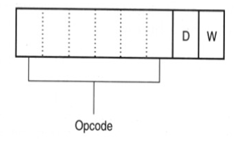
Fig 3 Position of D and W bits
The first six bits of the 1-byte are binary opcode and the remaining two bits indicate the direction D of data flow and whether the data are byte or a word W.
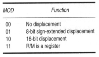
The MOD field specifies the addressing mode or the type of addressing for the selected instruction and whether the displacement is present with the selected type.
|
Fig 4 MOD for 16-bit instruction mode
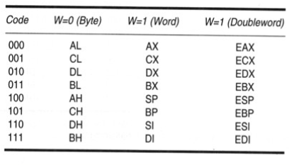
Register Assignment
|
Fig 5 Register Assignment
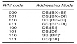
R/M Memory Addressing
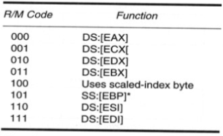
The R/M has different meaning if MOD field has 00, 01 or 10 as shown below.
|
Fig 6 R/M Addressing
The machine language instruction for 16-bit MOV DL, DI is shown below.
|
Fig 7 32-bit addressing mode selected by R/M
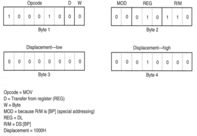
Special addressing mode
|
Fig 8 Special Addressing Mode used by MOV [1000H], DL
Immediate Instruction
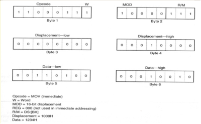
The instruction MOV WORD PTR [BX + 1000H], 1234H moves 1234 into the word sized memory location addressed by the sum of 1000H, BX and DSx10H.
|
Fig 9 MOV WORD PTR [BX + 1000H], 1234H converted to Binary
Segment MOV Instruction
If the content of a segment register is moved by MOV, PUSH or POP instruction a special register bit selects the segment register. The segment register can be moved between any 16-bit memory location.
3.1.2 PUSH/POP
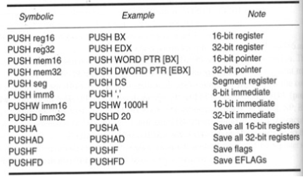
The PUSHF copies the content of flag register to the stack. PUSHAD and POPAD instructions push and pop the contents of the 32-bit register set in 80386 - Pentium 4. PUSHA and POPA instructions do not function in the 64-bit mode of operation for the Pentium 4
|
Fig 10 PUSH Instructions
The POP instruction removes data from the stack and places it into the target 16-bit register. POPF removes 16-bit number from the stack and places it into the flag register. The POPFD removes 32-bit number from the stack and places it into the extended flag register. POPA removes 16-bit data from stack and places it into the register in following order DI, SI, BP, SP, BX, DX, CX, AX.
3.1.3 Load-Effective Address
Instructions to transfer the address
- LEA − It loads the address of operand to the given register.
- LDS − Used to load DS register and other given register from the memory
- LES − Used to load ES register and other given register from the memory.
Instructions to transfer flag registers
- LAHF − It loads AH with the lower byte of the flag register.
- SAHF − It stores AH register to lower byte of the flag register.
- PUSHF − It copies the flag register at the top of the stack.
- POPF − It copies a word at the top of the stack.
3.1.4 String Data Transfers
It is a group of words and their memory is always placed in a sequential order.
Following are the instructions under this group −
- REP − It repeats the given instruction till CX ≠ 0.
- REPE/REPZ − It repeats the given instruction until zero flag ZF = 1 or CX = 0.
- REPNE/REPNZ − It repeats the given instruction until zero flag ZF = 1 or CX = 0.
- MOVS/MOVSB/MOVSW − It moves the byte from one string to another.
- COMS/COMPSB/COMPSW − It compares two string bytes.
- INS/INSB/INSW – It’s an input string byte from the I/O port given to the memory location.
- OUTS/OUTSB/OUTSW − It’s an input string byte from the memory location to the I/O port.
- SCAS/SCASB/SCASW − It scan’s a string and compares its byte with a byte present in AL or string word with a word present in AX.
- LODS/LODSB/LODSW − It stores the string byte into AL or AX.
3.1.5 Miscellaneous
Instructions to transfer the instruction during an execution without any condition
- CALL − It calls a procedure and at the same time saves their return address to the stack.
- RET − It returns from the procedure to the main program.
- JMP − It jumps to the given address to proceed to the next instruction.
These instructions are used to control the processor action by setting/resetting the flag values.
Following are the instructions under this group −
- STC – It sets CF to 1
- CLC – It clears CF to 0
- CMC − It complements the carry flag CF.
- STD − It sets the direction flag DF to 1
- CLD – It clears the direction flag DF to 0
- STI − It enables INTR input.
- CLI − It clears the interrupt enable flag.
They are used to call the interrupt during program execution.
- INT − It interrupts the program execution and calling service specified.
- INTO − It interrupts the program execution if OF = 1
- IRET − It helps to return from interrupt service routine to the main program.
Key takeaways
The POP instruction removes data from the stack and places it into the target 16-bit register. POPF removes 16-bit number from the stack and places it into the flag register.
The PUSH instruction transfers two or four bytes of data to the stack. It copies content of the internal register set, except the segment registers to the stack.
They are used for transferring the data from source operand to destination operand.
Instruction to transfer a word
- MOV – It is used to copy the byte from source to destination.
- PUSH − It is used to put a word at the top of the stack.
- POP − It gets a word from the top of the stack to the provided location.
- PUSHA − It puts all the registers into the stack.
- POPA − It gets words from the stack to all registers.
- XCHG − It exchanges the data from any two locations.
- XLAT − It translates a byte in AL using a table present in the memory.
mov ax, [es:60126] Use es as the segment
mov ax, [cs:bx] Use cs as the segment
mov ax, [ss:bp+si+3] Use ss as the segment
They are also called as pseudo-opcode. These instructions are neither translated into machine code nor assigned any memory location in the object file. Some of the important assembler directives for an assembler or a cross assembler are listed and described here.
Data -Bytes (Data Bytes): Assemble bytes of data are stored in successive memory location until all values are stored. This is a convenient way of writing a data string.
Exapmle-1
If we do not use
LDA, 4150H
MOV B,A
Or
MVI B, 25H
MOV A, B
We use DB, 25H, 29H
Data Word (DB)
It is used to just initialise an area of 2 bytes at a time. For example: DW 2050H
Data Quard Word (DQ)
It initialises 4 word or 8-bits in one instruction that means we take word which occupy a 8-bit number of decimal. For example: DQ 2050 95 76 30 75 95 86 H
Definite 10 Bit (DT)
It is similar to DQ but it occupies 2 bits extra. For example: DT 1 2 3 4 5 6 7 8 9 0 1 2 3 4 5 6 7 8 9 AB H.
Define Double Word (DD)
It is similar to DQ and DT. For example: DD 2050 60 75H
Definite Storage Location (DS)
Reserves a specified number of memory locations. In this example four memory locations are reserved for OUTBUF. For example: OUTBUF DS4
ORG
If we use ORG 4000H that means the next block of instructions should be stored in memory location starting 4000H.
EQU (equate)
Generally, we transfer any information in port address. Instead of
MVI A, 09H
OUT PA
PA EQU 40H
END
It is similar to HALT. But the HLT suggest the end of program but that does not necessarily mean it is the end of the assembly.
Key takeaway
Instructions are the codes given to the microprocessor by the user in order to perform various operations. They can be arithmetical, logical, machine control etc.
Instructions to perform addition
- ADD − It adds the provided word to word.
- ADC − It adds word with carry.
- INC − It increments the provided byte by 1.
- AAA − It adjusts ASCII after addition.
- DAA − It is decimal adjust.
Instructions to perform subtraction
- SUB − It subtracts the byte from byte.
- SBB − It performs subtraction with borrow.
- DEC − It decrements the provided byte by 1.
- NPG − It negates each bit of the provided byte and add 1’s / 2’s complement.
- CMP − It compares two given byte/word.
- AAS − It adjusts ASCII codes after subtraction.
- DAS − It is decimal adjust after subtraction.
Key takeaways
AAA − It adjusts ASCII after addition.
AAS − It adjusts ASCII codes after subtraction.
Instruction to perform multiplication
- MUL − It multiplies unsigned byte by byte or word by word.
- IMUL − It multiplies signed byte by byte or word by word.
- AAM − It adjusts ASCII codes after multiplication.
Instructions to perform division
- DIV − It divides the unsigned word or unsigned double word by word.
- IDIV − It divides the signed word or signed double word by word.
- AAD − It is ASCII adjust after division.
- CBW − It copies of sign bit of the lower byte.
- CWD − It fills the upper word of the double word with the sign bit of the lower word.
Key takeaway
IDIV − It divides the signed word or signed double word by word.
Reference:
1. Gaonkar, Ramesh S, “Microprocessor Architecture, Programming and Applications with 8085”, Penram International Publishing.
2. Ray A K, Bhurchandi K M, “Advanced Microprocessors and Peripherals”, TMH Hall D V, Microprocessor Interfacing’, TMH
3.Liu and, “Introduction to Microprocessor”, TMH
4. Brey, Barry B, “INTEL Microprocessors”, PHI


