Addressing Modes– The term addressing modes refers to the way in which the operand of an instruction is specified. The addressing mode specifies a rule for interpreting or modifying the address field of the instruction before the operand is actually executed.
Addressing modes for 8086 instructions are divided into two categories:
1) Addressing modes for data
2) Addressing modes for branch
The 8086 memory addressing modes provide flexible access to memory, allowing you to easily access variables, arrays, records, pointers, and other complex data types. The key to good assembly language programming is the proper use of memory addressing modes.
An assembly language program instruction consists of two parts
|
The memory address of an operand consists of two components:
IMPORTANT TERMS
- Starting address of memory segment.
- Effective address or Offset: An offset is determined by adding any combination of three address elements: displacement, base and index.
- Displacement: It is an 8 bit or 16 bit immediate value given in the instruction.
- Base: Contents of base register, BX or BP.
- Index: Content of index register SI or DI.
According to different ways of specifying an operand by 8086 microprocessor, different addressing modes are used by 8086.
Addressing modes used by 8086 microprocessor are discussed below:
- Implied mode: In implied addressing the operand is specified in the instruction itself. In this mode the data is 8 bits or 16 bits long and data is the part of instruction. Zero address instruction are designed with implied addressing mode.
|
Example: CLC (used to reset Carry flag to 0)
- Immediate addressing mode (symbol #): In this mode data is present in address field of instruction. Designed like one address instruction format.
Note: Limitation in the immediate mode is that the range of constants are restricted by size of address field.
|
Example: MOV AL, 35H (move the data 35H into AL register)
- Register mode: In register addressing the operand is placed in one of 8 bit or 16-bit general purpose registers. The data is in the register that is specified by the instruction. Here one register reference is required to access the data.
|
Example: MOV AX, CX (move the contents of CX register to AX register)
- Register Indirect mode: In this addressing the operand’s offset is placed in any one of the registers BX, BP, SI, DI as specified in the instruction. The effective address of the data is in the base register or an index register that is specified by the instruction. Here two register reference is required to access the data.
|
The 8086 CPUs let you access memory indirectly through a register using the register indirect addressing modes.
- MOV AX, [BX](move the contents of memory location s
addressed by the register BX to the register AX)
- Auto Indexed (increment mode): Effective address of the operand is the contents of a register specified in the instruction. After accessing the operand, the contents of this register are automatically incremented to point to the next consecutive memory location. (R1)+.
Here one register reference, one memory reference and one ALU operation is required to access the data.
Example:
- Add R1, (R2) + // OR
- R1 = R1 +M[R2]
R2 = R2 + d
Useful for stepping through arrays in a loop. R2 – start of array d – size of an element
- Auto indexed (decrement mode): Effective address of the operand is the contents of a register specified in the instruction. Before accessing the operand, the contents of this register are automatically decremented to point to the previous consecutive memory location. –(R1)
Here one register reference, one memory reference and one ALU operation is required to access the data.
Example:
Add R1, -(R2) //OR
R2 = R2-d
R1 = R1 + M[R2]
Auto decrement mode is same as auto increment mode. Both can also be used to implement a stack as push and pop. Auto increment and Auto decrement modes are useful for implementing “Last-In-First-Out” data structures.
- Direct addressing/ Absolute addressing Mode (symbol [ ]): The operand’s offset is given in the instruction as an 8 bit or 16 bit displacement element. In this addressing mode the 16-bit effective address of the data is the part of the instruction.
Here only one memory reference operation is required to access the data.
|
Example: ADD AL, [0301] //add the contents of offset address 0301 to AL
- Indirect addressing Mode (symbol @ or ()): In this mode address field of instruction contains the address of effective address. Here two references are required. 1st reference to get effective address. 2nd reference to access the data.
Based on the availability of Effective address, Indirect mode is of two kind:
- Register Indirect: In this mode effective address is in the register, and corresponding register name will be maintained in the address field of an instruction. Here one register reference, one memory reference is required to access the data.
- Memory Indirect: In this mode effective address is in the memory, and corresponding memory address will be maintained in the address field of an instruction. Here two memory reference is required to access the data.
- Indexed addressing mode: The operand’s offset is the sum of the content of an index register SI or DI and an 8 bit or 16-bit displacement.
Example: MOV AX, [SI +05]
- Based Indexed Addressing: The operand’s offset is sum of the content of a base register BX or BP and an index register SI or DI.
Example: ADD AX, [BX+SI]
Based on Transfer of control, addressing modes are:
- PC relative addressing mode: PC relative addressing mode is used to implement intra segment transfer of control, in this mode effective address is obtained by adding displacement to PC.
- EA= PC + Address field value
PC= PC + Relative value.
3. Base register addressing mode: Base register addressing mode is used to implement inter segment transfer of control. In this mode effective address is obtained by adding base register value to address field value.
4. EA= Base register + Address field value.
5. PC= Base register + Relative value.
Note:
PC relative and based register both addressing modes are suitable for program relocation at runtime.
Based register addressing mode is best suitable to write position independent codes.
Advantages of Addressing Modes
To give programmers to facilities such as Pointers, counters for loop controls, indexing of data and program relocation.
To reduce the number bits in the addressing field of the Instruction.
Key takeaways
- Addressing Modes– The term addressing modes refers to the way in which the operand of an instruction is specified. The addressing mode specifies a rule for interpreting or modifying the address field of the instruction before the operand is actually executed.
Each personal computer has a microprocessor that manages the computer's arithmetical, logical, and control activities.
Each family of processors has its own set of instructions for handling various operations such as getting input from keyboard, displaying information on screen and performing various other jobs. These set of instructions are called 'machine language instructions'.
A processor understands only machine language instructions, which are strings of 1's and 0's. However, machine language is too obscure and complex for using in software development. So, the low-level assembly language is designed for a specific family of processors that represents various instructions in symbolic code and a more understandable form.
Advantages of Assembly Language
Having an understanding of assembly language makes one aware of −
- How programs interface with OS, processor, and BIOS;
- How data is represented in memory and other external devices;
- How the processor accesses and executes instruction;
- How instructions access and process data;
- How a program accesses external devices.
Other advantages of using assembly language are −
- It requires less memory and execution time;
- It allows hardware-specific complex jobs in an easier way;
- It is suitable for time-critical jobs;
- It is most suitable for writing interrupt service routines and other memory resident programs.
The main internal hardware of a PC consists of processor, memory, and registers. Registers are processor components that hold data and address. To execute a program, the system copies it from the external device into the internal memory. The processor executes the program instructions.
The fundamental unit of computer storage is a bit; it could be ON (1) or OFF (0) and a group of 8 related bits makes a byte on most of the modern computers.
So, the parity bit is used to make the number of bits in a byte odd. If the parity is even, the system assumes that there had been a parity error (though rare), which might have been caused due to hardware fault or electrical disturbance.
The processor supports the following data sizes −
- Word: a 2-byte data item
- Doubleword: a 4-byte (32 bit) data item
- Quadword: an 8-byte (64 bit) data item
- Paragraph: a 16-byte (128 bit) area
- Kilobyte: 1024 bytes
- Megabyte: 1,048,576 bytes
Every number system uses positional notation, i.e., each position in which a digit is written has a different positional value. Each position is power of the base, which is 2 for binary number system, and these powers begin at 0 and increase by 1.
The following table shows the positional values for an 8-bit binary number, where all bits are set ON.
Bit value | 1 | 1 | 1 | 1 | 1 | 1 | 1 | 1 |
Position value as a power of base 2 | 128 | 64 | 32 | 16 | 8 | 4 | 2 | 1 |
Bit number | 7 | 6 | 5 | 4 | 3 | 2 | 1 | 0 |
The value of a binary number is based on the presence of 1 bits and their positional value. So, the value of a given binary number is −
1 + 2 + 4 + 8 +16 + 32 + 64 + 128 = 255 which is same as 28 - 1. |
Hexadecimal Number System
Hexadecimal number system uses base 16. The digits in this system range from 0 to 15. By convention, the letters A through F is used to represent the hexadecimal digits corresponding to decimal values 10 through 15.
Hexadecimal numbers in computing is used for abbreviating lengthy binary representations. Basically, hexadecimal number system represents a binary data by dividing each byte in half and expressing the value of each half-byte. The following table provides the decimal, binary, and hexadecimal equivalents −
Decimal number | Binary representation | Hexadecimal representation |
0 | 0 | 0 |
1 | 1 | 1 |
2 | 10 | 2 |
3 | 11 | 3 |
4 | 100 | 4 |
5 | 101 | 5 |
6 | 110 | 6 |
7 | 111 | 7 |
8 | 1000 | 8 |
9 | 1001 | 9 |
10 | 1010 | A |
11 | 1011 | B |
12 | 1100 | C |
13 | 1101 | D |
14 | 1110 | E |
15 | 1111 | F |
To convert a binary number to its hexadecimal equivalent, break it into groups of 4 consecutive groups each, starting from the right, and write those groups over the corresponding digits of the hexadecimal number.
Example − Binary number 1000 1100 1101 0001 is equivalent to hexadecimal - 8CD1
To convert a hexadecimal number to binary, just write each hexadecimal digit into its 4-digit binary equivalent.
Example − Hexadecimal number FAD8 is equivalent to binary - 1111 1010 1101 1000
The following table illustrates four simple rules for binary addition −
(i) | (ii) | (iii) | (iv) |
|
|
| 1 |
0 | 1 | 1 | 1 |
+0 | +0 | +1 | +1 |
=0 | =1 | =10 | =11 |
Rules (iii) and (iv) show a carry of a 1-bit into the next left position.
Example
Decimal | Binary |
60 | 00111100 |
+42 | 00101010 |
102 | 01100110 |
A negative binary value is expressed in two's complement notation. According to this rule, to convert a binary number to its negative value is to reverse its bit values and add 1.
Example
Number 53 | 00110101 |
Reverse the bits | 11001010 |
Add 1 | 00000001 |
Number -53 | 11001011 |
To subtract one value from another, convert the number being subtracted to two's complement format and add the numbers.
Example
Subtract 42 from 53
Number 53 | 00110101 |
Number 42 | 00101010 |
Reverse the bits of 42 | 11010101 |
Add 1 | 00000001 |
Number -42 | 11010110 |
53 - 42 = 11 | 00001011 |
Overflow of the last 1 bit is lost.
The process through which the processor controls the execution of instructions is referred as the fetch-decode-execute cycle or the execution cycle. It consists of three continuous steps −
- Fetching the instruction from memory
- Decoding or identifying the instruction
- Executing the instruction
The processor may access one or more bytes of memory at a time. Let us consider a hexadecimal number 0725H. This number will require two bytes of memory. The high-order byte or most significant byte is 07 and the low-order byte is 25.
The processor stores data in reverse-byte sequence, i.e., a low-order byte is stored in a low memory address and a high-order byte in high memory address. So, if the processor brings the value 0725H from register to memory, it will transfer 25 first to the lower memory address and 07 to the next memory address.
|
x: memory address
When the processor gets the numeric data from memory to register, it again reverses the bytes. There are two kinds of memory addresses −
- Absolute address - a direct reference of specific location.
- Segment address (or offset) - starting address of a memory segment with the offset value.
Key takeaways
- Each personal computer has a microprocessor that manages the computer's arithmetical, logical, and control activities.
- Each family of processors has its own set of instructions for handling various operations such as getting input from keyboard, displaying information on screen and performing various other jobs. These set of instructions are called 'machine language instructions'.
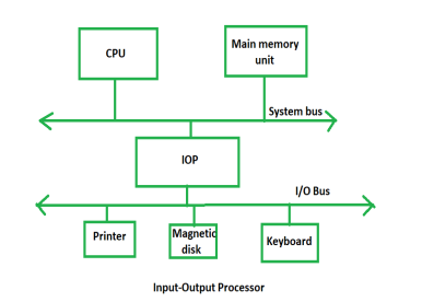
The DMA mode of data transfer reduces CPU’s overhead in handling I/O operations. It also allows parallelism in CPU and I/O operations. Such parallelism is necessary to avoid wastage of valuable CPU time while handling I/O devices whose speeds are much slower as compared to CPU. The concept of DMA operation can be extended to relieve the CPU further from getting involved with the execution of I/O operations. This gives rises to the development of special purpose processor called Input-Output Processor (IOP) or IO channel.
The Input Output Processor (IOP) is just like a CPU that handles the details of I/O operations. It is more equipped with facilities than those are available in typical DMA controller. The IOP can fetch and execute its own instructions that are specifically designed to characterize I/O transfers. In addition to the I/O – related tasks, it can perform other processing tasks like arithmetic, logic, branching and code translation. The main memory unit takes the pivotal role. It communicates with processor by the means of DMA.
The block diagram –
|
Fig 1 – Input – Output Process
The Input Output Processor is a specialized processor which loads and stores data into memory along with the execution of I/O instructions. It acts as an interface between system and devices. It involves a sequence of events to executing I/O operations and then store the results into the memory.
Advantages –
- The I/O devices can directly access the main memory without the intervention by the processor in I/O processor-based systems.
- It is used to address the problems that are arises in Direct memory access method.
Key takeaways
- The DMA mode of data transfer reduces CPU’s overhead in handling I/O operations. It also allows parallelism in CPU and I/O operations. Such parallelism is necessary to avoid wastage of valuable CPU time while handling I/O devices whose speeds are much slower as compared to CPU. The concept of DMA operation can be extended to relieve the CPU further from getting involved with the execution of I/O operations. This gives rises to the development of special purpose processor called Input-Output Processor (IOP) or IO channel.
STACKs
A Stack is a linear data structure that follows the LIFO (Last-In-First-Out) principle. Stack has one end, whereas the Queue has two ends (front and rear). It contains only one pointer top pointer pointing to the topmost element of the stack. Whenever an element is added in the stack, it is added on the top of the stack, and the element can be deleted only from the stack. In other words, a stack can be defined as a container in which insertion and deletion can be done from the one end known as the top of the stack.
Some key points related to stack
- It is called as stack because it behaves like a real-world stack, piles of books, etc.
- A Stack is an abstract data type with a pre-defined capacity, which means that it can store the elements of a limited size.
- It is a data structure that follows some order to insert and delete the elements, and that order can be LIFO or FILO.
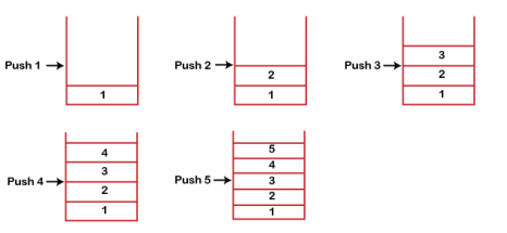
Stack works on the LIFO pattern. As we can observe in the below figure there are five memory blocks in the stack; therefore, the size of the stack is 5.
Suppose we want to store the elements in a stack and let's assume that stack is empty. We have taken the stack of size 5 as shown below in which we are pushing the elements one by one until the stack becomes full.
|
Fig 2 - Stack
Since our stack is full as the size of the stack is 5. In the above cases, we can observe that it goes from the top to the bottom when we were entering the new element in the stack. The stack gets filled up from the bottom to the top.
When we perform the delete operation on the stack, there is only one way for entry and exit as the other end is closed. It follows the LIFO pattern, which means that the value entered first will be removed last. In the above case, the value 5 is entered first, so it will be removed only after the deletion of all the other elements.
The following are some common operations implemented on the stack:
- push(): When we insert an element in a stack then the operation is known as a push. If the stack is full then the overflow condition occurs.
- pop(): When we delete an element from the stack, the operation is known as a pop. If the stack is empty means that no element exists in the stack, this state is known as an underflow state.
- isEmpty(): It determines whether the stack is empty or not.
- isFull(): It determines whether the stack is full or not.'
- peek(): It returns the element at the given position.
- count(): It returns the total number of elements available in a stack.
- change(): It changes the element at the given position.
- display(): It prints all the elements available in the stack.
PUSH operation
The steps involved in the PUSH operation is given below:
- Before inserting an element in a stack, we check whether the stack is full.
- If we try to insert the element in a stack, and the stack is full, then the overflow condition occurs.
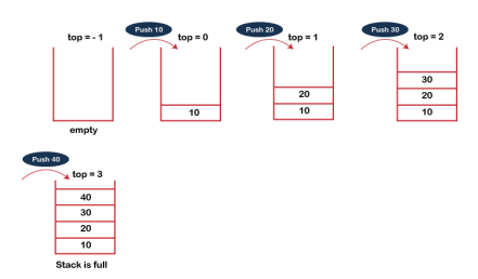
- When we initialize a stack, we set the value of top as -1 to check that the stack is empty.
- When the new element is pushed in a stack, first, the value of the top gets incremented, i.e., top=top+1, and the element will be placed at the new position of the top.
- The elements will be inserted until we reach the max size of the stack.
|
Fig 3 – Push operation
The steps involved in the POP operation is given below:
- Before deleting the element from the stack, we check whether the stack is empty.
- If we try to delete the element from the empty stack, then the underflow condition occurs.
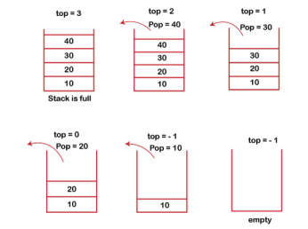
- If the stack is not empty, we first access the element which is pointed by the top
- Once the pop operation is performed, the top is decremented by 1, i.e., top=top-1.
|
Fig 4 – POP operation
The following are the applications of the stack:
- Balancing of symbols: Stack is used for balancing a symbol. For example, we have the following program:
|
As we know, each program has an opening and closing braces; when the opening braces come, we push the braces in a stack, and when the closing braces appear, we pop the opening braces from the stack. Therefore, the net value comes out to be zero. If any symbol is left in the stack, it means that some syntax occurs in a program.
- String reversal: Stack is also used for reversing a string. For example, we want to reverse a "javaTpoint" string, so we can achieve this with the help of a stack. First, we push all the characters of the string in a stack until we reach the null character. After pushing all the characters, we start taking out the character one by one until we reach the bottom of the stack.
- UNDO/REDO: It can also be used for performing UNDO/REDO operations. For example, we have an editor in which we write 'a', then 'b', and then 'c'; therefore, the text written in an editor is abc. So, there are three states, a, ab, and abc, which are stored in a stack. There would be two stacks in which one stack shows UNDO state, and the other shows REDO state. If we want to perform UNDO operation, and want to achieve 'ab' state, then we implement pop operation.
- Recursion: The recursion means that the function is calling itself again. To maintain the previous states, the compiler creates a system stack in which all the previous records of the function are maintained.
- DFS (Depth First Search): This search is implemented on a Graph, and Graph uses the stack data structure.
- Backtracking: Suppose we have to create a path to solve a maze problem. If we are moving in a particular path, and we realize that we come on the wrong way. In order to come at the beginning of the path to create a new path, we have to use the stack data structure.
- Expression conversion: Stack can also be used for expression conversion. This is one of the most important applications of stack. The list of the expression conversion is given below:
- Infix to prefix
- Infix to postfix
- Prefix to infix
- Prefix to postfix
Postfix to infix
- Memory management: The stack manages the memory. The memory is assigned in the contiguous memory blocks. The memory is known as stack memory as all the variables are assigned in a function call stack memory. The memory size assigned to the program is known to the compiler. When the function is created, all its variables are assigned in the stack memory. When the function completed its execution, all the variables assigned in the stack are released.
QUEUEs
1. A queue can be defined as an ordered list which enables insert operations to be performed at one end called REAR and delete operations to be performed at another end called FRONT.
2. Queue is referred to be as First In First Out list.
3. For example, people waiting in line for a rail ticket form a queue.
|
Fig 5 - QUEUE
Due to the fact that queue performs actions on first in first out basis which is quite fair for the ordering of actions. There are various applications of queues discussed as below.
- Queues are widely used as waiting lists for a single shared resource like printer, disk, CPU.
- Queues are used in asynchronous transfer of data (where data is not being transferred at the same rate between two processes) for eg. pipes, file IO, sockets.
- Queues are used as buffers in most of the applications like MP3 media player, CD player, etc.
- Queue are used to maintain the play list in media players in order to add and remove the songs from the play-list.
- Queues are used in operating systems for handling interrupts.
Data Structure | Time Complexity | Space Compleity | |||||||
| Average | Worst | Worst | ||||||
| Access | Search | Insertion | Deletion | Access | Search | Insertion | Deletion |
|
Queue | θ(n) | θ(n) | θ(1) | θ(1) | O(n) | O(n) | O(1) | O(1) | O(n) |
A queue in the data structure can be considered similar to the queue in the real-world. A queue is a data structure in which whatever comes first will go out first. It follows the FIFO (First-In-First-Out) policy. In Queue, the insertion is done from one end known as the rear end or the tail of the queue, whereas the deletion is done from another end known as the front end or the head of the queue. In other words, it can be defined as a list or a collection with a constraint that the insertion can be performed at one end called as the rear end or tail of the queue and deletion is performed on another end called as the front end or the head of the queue.
|
Fig 6 - Dequeue
There are two fundamental operations performed on a Queue:
- Enqueue: The enqueue operation is used to insert the element at the rear end of the queue. It returns void.
- Dequeue: The dequeue operation performs the deletion from the front-end of the queue. It also returns the element which has been removed from the front-end. It returns an integer value. The dequeue operation can also be designed to void.
- Peek: This is the third operation that returns the element, which is pointed by the front pointer in the queue but does not delete it.
- Queue overflow (isfull): When the Queue is completely full, then it shows the overflow condition.
- Queue underflow (isempty): When the Queue is empty, i.e., no elements are in the Queue then it throws the underflow condition.
A Queue can be represented as a container opened from both the sides in which the element can be enqueued from one side and dequeued from another side as shown in the below figure:
There are two ways of implementing the Queue:
- Sequential allocation: The sequential allocation in a Queue can be implemented using an array.
- Linked list allocation: The linked list allocation in a Queue can be implemented using a linked list.
What are the use cases of Queue?
Here, we will see the real-world scenarios where we can use the Queue data structure. The Queue data structure is mainly used where there is a shared resource that has to serve the multiple requests but can serve a single request at a time. In such cases, we need to use the Queue data structure for queuing up the requests. The request that arrives first in the queue will be served first. The following are the real-world scenarios in which the Queue concept is used:
- Suppose we have a printer shared between various machines in a network, and any machine or computer in a network can send a print request to the printer. But, the printer can serve a single request at a time, i.e., a printer can print a single document at a time. When any print request comes from the network, and if the printer is busy, the printer's program will put the print request in a queue.
- . If the requests are available in the Queue, the printer takes a request from the front of the queue, and serves it.
- The processor in a computer is also used as a shared resource. There are multiple requests that the processor must execute, but the processor can serve a single request or execute a single process at a time. Therefore, the processes are kept in a Queue for execution.
There are four types of Queues:
- Linear Queue
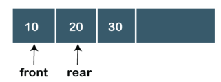
In Linear Queue, an insertion takes place from one end while the deletion occurs from another end. The end at which the insertion takes place is known as the rear end, and the end at which the deletion takes place is known as front end. It strictly follows the FIFO rule. The linear Queue can be represented, as shown in the below figure:
|
Fig 7 – Linear queue
The above figure shows that the elements are inserted from the rear end, and if we insert more elements in a Queue, then the rear value gets incremented on every insertion. If we want to show the deletion, then it can be represented as:
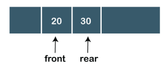
|
In the above figure, we can observe that the front pointer points to the next element, and the element which was previously pointed by the front pointer was deleted.
The major drawback of using a linear Queue is that insertion is done only from the rear end. If the first three elements are deleted from the Queue, we cannot insert more elements even though the space is available in a Linear Queue. In this case, the linear Queue shows the overflow condition as the rear is pointing to the last element of the Queue.
- Circular Queue
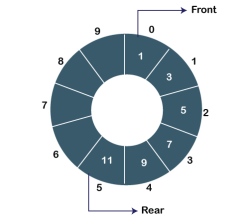
In Circular Queue, all the nodes are represented as circular. It is similar to the linear Queue except that the last element of the queue is connected to the first element. It is also known as Ring Buffer as all the ends are connected to another end. The circular queue can be represented as:
|
Fig 8 – Circular queue
The drawback that occurs in a linear queue is overcome by using the circular queue. If the empty space is available in a circular queue, the new element can be added in an empty space by simply incrementing the value of rear.
- Priority Queue
A priority queue is another special type of Queue data structure in which each element has some priority associated with it. Based on the priority of the element, the elements are arranged in a priority queue. If the elements occur with the same priority, then they are served according to the FIFO principle.
In priority Queue, the insertion takes place based on the arrival while the deletion occurs based on the priority. The priority Queue can be shown as:
The above figure shows that the highest priority element comes first and the elements of the same priority are arranged based on FIFO structure.
- Deque
Both the Linear Queue and Deque are different as the linear queue follows the FIFO principle whereas, deque does not follow the FIFO principle. In Deque, the insertion and deletion can occur from both ends.
Key takeaways
- A Stack is a linear data structure that follows the LIFO (Last-In-First-Out) principle. Stack has one end, whereas the Queue has two ends (front and rear). It contains only one pointer top pointer pointing to the topmost element of the stack. Whenever an element is added in the stack, it is added on the top of the stack, and the element can be deleted only from the stack. In other words, a stack can be defined as a container in which insertion and deletion can be done from the one end known as the top of the stack.
- A queue in the data structure can be considered similar to the queue in the real-world. A queue is a data structure in which whatever comes first will go out first. It follows the FIFO (First-In-First-Out) policy. In Queue, the insertion is done from one end known as the rear end or the tail of the queue, whereas the deletion is done from another end known as the front end or the head of the queue. In other words, it can be defined as a list or a collection with a constraint that the insertion can be performed at one end called as the rear end or tail of the queue and deletion is performed on another end called as the front end or the head of the queue.
1. Subroutine –
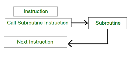
A set of Instructions which are used repeatedly in a program can be referred to as Subroutine. Only one copy of this Instruction is stored in the memory. When a Subroutine is required it can be called many times during the Execution of a Particular program. A call Subroutine Instruction calls the Subroutine. Care Should be taken while returning a Subroutine as Subroutine can be called from a different place from the memory.
The content of the PC must be Saved by the call Subroutine Instruction to make a correct return to the calling program.
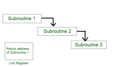
|
Fig 9 – Process of subroutine in a program
Subroutine linkage method is a way in which computer call and return the Subroutine. The simplest way of Subroutine linkage is saving the return address in a specific location, such as register which can be called as link register call Subroutine.
2. Subroutine Nesting –
Subroutine nesting is a common Programming practice In which one Subroutine call another Subroutine.
|
Fig 10 – Subroutine calling another subroutine
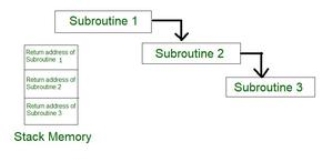
From the above figure, assume that when Subroutine 1 calls Subroutine 2 the return address of Subroutine 2 should be saved somewhere. So if link register stores return address of Subroutine 1 this will be (destroyed/overwritten) by return address of Subroutine 2. As the last Subroutine called is the first one to be returned (Last in first out format). So, stack data structure is the most efficient way to store the return addresses of the Subroutines.
|
Fig 11 – Return address of subroutine is stored in stack memory
3. Stack memory –
Stack is a basic data structure which can be implemented anywhere in the memory. It can be used to store variables which may be required afterwards in the program Execution. In a stack, the first data put will be last to get out of a stack. So the last data added will be the First one to come out of the stack (last in first out).
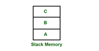
|
Fig 12 – Stack memory having data A, B & C
So, from the diagram above first A is added then B & C. While removing first C is Removed then B & A.
Key takeaways
- A set of Instructions which are used repeatedly in a program can be referred to as Subroutine. Only one copy of this Instruction is stored in the memory. When a Subroutine is required it can be called many times during the Execution of a Particular program. A call Subroutine Instruction calls the Subroutine. Care Should be taken while returning a Subroutine as Subroutine can be called from a different place from the memory.
Computer instructions are a set of machine language instructions that a particular processor understands and executes. A computer performs tasks on the basis of the instruction provided.
An instruction comprises of groups called fields. These fields include:
- The Operation code (Opcode) field which specifies the operation to be performed.
- The Address field which contains the location of the operand, i.e., register or memory location.
- The Mode field which specifies how the operand will be located.
|
A basic computer has three instruction code formats which are:
- Memory - reference instruction
- Register - reference instruction
- Input-Output instruction
Fig 13 - Memory - reference instruction
|
In Memory-reference instruction, 12 bits of memory is used to specify an address and one bit to specify the addressing mode 'I'.
Fig 14 - Register - reference instruction
|
The Register-reference instructions are represented by the Opcode 111 with a 0 in the leftmost bit (bit 15) of the instruction.
Note: The Operation code (Opcode) of an instruction refers to a group of bits that define arithmetic and logic operations such as add, subtract, multiply, shift, and compliment.
A Register-reference instruction specifies an operation on or a test of the AC (Accumulator) register.
Fig 15 - Input-Output instruction
|
Just like the Register-reference instruction, an Input-Output instruction does not need a reference to memory and is recognized by the operation code 111 with a 1 in the leftmost bit of the instruction. The remaining 12 bits are used to specify the type of the input-output operation or test performed.
- The three operation code bits in positions 12 through 14 should be equal to 111. Otherwise, the instruction is a memory-reference type, and the bit in position 15 is taken as the addressing mode I.
- When the three operation code bits are equal to 111, control unit inspects the bit in position 15. If the bit is 0, the instruction is a register-reference type. Otherwise, the instruction is an input-output type having bit 1 at position 15.
A set of instructions is said to be complete if the computer includes a sufficient number of instructions in each of the following categories:
- Arithmetic, logical and shift instructions
- A set of instructions for moving information to and from memory and processor registers.
- Instructions which controls the program together with instructions that check status conditions.
- Input and Output instructions
Arithmetic, logic and shift instructions provide computational capabilities for processing the type of data the user may wish to employ.
A huge amount of binary information is stored in the memory unit, but all computations are done in processor registers. Therefore, one must possess the capability of moving information between these two units.
Program control instructions such as branch instructions are used change the sequence in which the program is executed.
Input and Output instructions act as an interface between the computer and the user. Programs and data must be transferred into memory, and the results of computations must be transferred back to the user.
Key takeaways
- Computer instructions are a set of machine language instructions that a particular processor understands and executes. A computer performs tasks on the basis of the instruction provided.
- An instruction comprises of groups called fields. These fields include:
- The Operation code (Opcode) field which specifies the operation to be performed.
- The Address field which contains the location of the operand, i.e., register or memory location.
- The Mode field which specifies how the operand will be located.
An encoder can also be described as a combinational circuit that performs the inverse operation of a decoder. An encoder has a maximum of 2^n (or less) input lines and n output lines.
In an Encoder, the output lines generate the binary code corresponding to the input value.
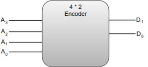
The following image shows the block diagram of a 4 * 2 encoder with four input and two output lines.
|
Fig 16 - Encoder
The truth table for a 4-to-2-line encoder can be represented as:
A3 | A2 | A1 | A0 | D1 | D0 |
0 | 0 | 0 | 1 | 0 | 0 |
0 | 0 | 1 | 0 | 0 | 1 |
0 | 1 | 0 | 0 | 1 | 0 |
1 | 0 | 0 | 0 | 1 | 1 |
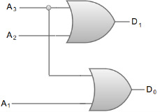
From the truth table, we can write the Boolean function for each output as:
D1 = A3 + A2
D0 = A3 + A1
The circuit diagram for a 4-to-2-line encoder can be represented by using two input OR gates.
|
Fig 17 – OR Gate
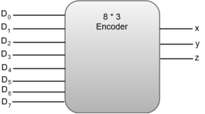
The most common application of an encoder is the Octal-to-Binary encoder. Octal to binary encoder takes eight input lines and generates three output lines.
The following image shows the block diagram of an 8 * 3-line encoder.
|
The truth table for an 8 * 3-line encoder can be represented as:
D7 | D6 | D5 | D4 | D3 | D2 | D1 | D0 | x | y | z |
0 | 0 | 0 | 0 | 0 | 0 | 0 | 1 | 0 | 0 | 0 |
0 | 0 | 0 | 0 | 0 | 0 | 1 | 0 | 0 | 0 | 1 |
0 | 0 | 0 | 0 | 0 | 1 | 0 | 0 | 0 | 1 | 0 |
0 | 0 | 0 | 0 | 1 | 0 | 0 | 0 | 0 | 1 | 1 |
0 | 0 | 0 | 1 | 0 | 0 | 0 | 0 | 1 | 0 | 0 |
0 | 0 | 1 | 0 | 0 | 0 | 0 | 0 | 1 | 0 | 1 |
0 | 1 | 0 | 0 | 0 | 0 | 0 | 0 | 1 | 1 | 0 |
1 | 0 | 0 | 0 | 0 | 0 | 0 | 0 | 1 | 1 | 1 |
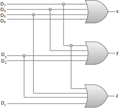
From the truth table, we can write the Boolean function for each output as:
x = D4 + D5 + D6 + D7
y = D2 + D3 + D6 + D7
z = D1 + D3 + D5 + D7
The circuit diagram for an 8 * 3-line encoder can be represented by using two input OR gates.
|
Fig 18 - Example
Key takeaways
- An encoder can also be described as a combinational circuit that performs the inverse operation of a decoder. An encoder has a maximum of 2^n (or less) input lines and n output lines.
- In an Encoder, the output lines generate the binary code corresponding to the input value.
References
1. William Stallings: Computer Organization & Architecture, 7th Edition, PHI, 2006.
2. Vincent P. Heuring & Harry F. Jordan: Computer Systems Design and Architecture, 2 nd Edition, Pearson Education, 2004.


