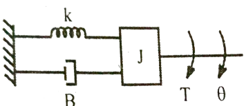
UNIT-1
Modelling of Systems
|
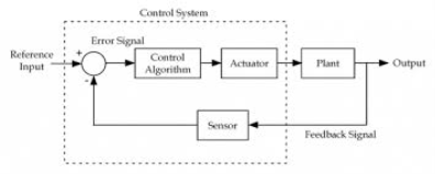
Fig 1 Block diagram for closed loop control system
The above figure shows a feedback system with a control system. The components of control system are:
i) The actuator takes the signal transforms it accordingly and causes some action.
ii) Sensors are used to measure continuous and discrete process variables.
iii) Controllers are those elements which adjust the actuators in response to the measurement.
Key takeaway:
- The feedback control system is having a sensor.
- These sensors help to improve accuracy by generating error signal.
Open loop systems:
This is the loop of control system without any feedback. In this the control action is not dependent on the desired output.
|
Fig. 2 open loop control system
Example of open Loop systems are the traffic signals, Automatic washing machine and in fields control d.c. motor.
G(s) = c(s)/R(s) -------(1)
Closed loop systems:
This is a type of control system with feedback. In this type of system. The control action is dependent on the desired output.
|
Fig 3 Closed Loop control system
The error signal is again fed to controller to the error and get desired output.
G(s) – forward amplification
H(s) _ Reverse amplification
Above system is with negative feedback.
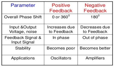
Positive feedback is used only in oscillators and other use is not known as discussing only negative feedback.
[ R(s) – c(s) H (S)] G(s) = c(s)
R (s) G(s) = [1+G(s) H(s)] c(s)
C(s)/R(S) = G(S)/1+G(s) H(s)
S0, the transfer function of closed Loop system is
C(s)/ R(S) = G(s)/ 1+G(S) H(S) --------(2)
- If numerator of above equation (2) is equalized to zero we get zeros of closed Loop Transfer function [G(S) = 0]
- If dominator of equation (2) is equaled to zero, we get polls of the closed loop transfer function [ 1+G(s) H(S) = 0]
1+ G(S) H(s) = 0 [ characteristic Equation]
- Stability of the system is determined by the location of its poles.
The transfer function of a linear time invariant system is the ratio of Laplace Transform
Comparisons between open Loop and Closed Loop system
Open Loop System | Closed Loop system |
1.It does Not have any feedback. | 1. This system comprise of feedback |
2.As no feedback so easier to build. | 2.As it has feedback so difficult to build |
3.Theaccuracy of this system depends on the calibration of input. | 3.They are accuracy because of the feedback. |
4.Open Loop system are more stable. | 4.In closed Loop system stability depends on system components. |
5.optimization is not possible | 5. optimization is possible |
6.These systems are not reliable. | They are more reliable |
Feedforward System:
The feedback system is which work to reduce the error it’s the system. In some system where the disturbances input can be provided beforehand, its effect can be eliminated by feedforward system.
Tracking System:
The main objective of such system is to trace any particular location as direction of a targeted value on continuous basic. The basic examples of tracking, Range tracking, Tracking in phased array radars.
Regulator System: The main objective of such systems is to maintain a designated characteristic they try to maintain a range of values is a machine for ex. Voltage regulator etc.
Key takeaway:
The open loop systems are without feedback.
The closed loop systems use feedback. In closed Loop system stability depends on system components.
There are two types of feedbacks
i) Positive Feedback
|
Fig 4 Closed Loop control system
In positive feedback systems the feedback signal is added to the input signal. The positive feedback is used only in oscillators. The transfer function is given as
C(s)/ R(S) = G(s)/ 1-G(S) H(S)
ii) Negative Feedback
In negative feedback the error signal is inverted at the input signal. The discussion in this unit is based on this negative feedback system only. The transfer function is given by
C(s)/ R(S) = G(s)/ 1+G(S) H(S)
Key takeaway
|
1.4.1 Mechanical systems
Mechanical System
(a) Translational system
(b) Rotational system
1.4.1.1 Translational mechanical system:
The motion that takes place along a straight line is called translational motion. The forces that resist motion are -
Inertia: A body with mass ‘N’ acceleration ‘a’ will produce inertia fm(t)= malt N’ acceleration ‘a’ will produce inertia
fm(t)= M a(t)
In terms of velocity
Fm(t) = M dv(t)/dt
In terms of displacement
Fm(t)= Md2/dt2µt
Damping force: The damping force is proportional to velocity for vis case function
F0(t) = B(t) = B dx(t) /dt
B Damping Coefficient N/M sec
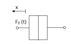
Fig 5 Damping Force
Spring force: A spring stores potential energy. The releasing force of a string is proportional to the displacement.
Fk(t)  x(t)
x(t)
Fk(t) = k x (t)
Fk(t) = k 
K = string constant N/m.

Fig 6 Spring Constant
1.4.1.2 Rotational mechanical system:
The motion of a body about a fixed axis is called as Rotational motion. The types of torques which can resist the motion are
Inertial Torque: - The inertial torque is the product of moment of inertia I and angular acceleration.
TI(t) = J (t)
(t)
TI(t) = Jd/dt w(t)
TI(t) = Jd2ø(t)/dt2(N-m)
W (t) – Angular velocity
Ø(t) = Angular displacement
Damping Torque: - it is product of damping efficient B and angular velocity w
T0 (t) = B w(t)
T0(t) = B d/dt ø(t)
Spring Torque: - It is the product of torsional stiffness and angular displacement
Tø(t) = k ø(t)
K = N.m/rad
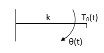
Fig 7 Spring Torque
D’Alembert’s Principle
Ex.
|
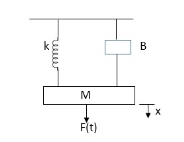
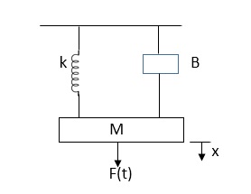
Fig 8 Mechanical System
In above figure applying D’Alembert’s principle to write the equation of motion
As force f(t) acts downwards all other forces (of k, B, x) acts Opposite to it considering f(t) as the and all other forces negative.
F(t)+fm (t) + fD(t) +fx(t) =0
f(t)- M d2x(t)/dt2+B dx(t)/dt +x(t)
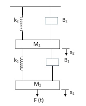
Q.1 Draw the free body diagram and write the differential equation for system below.
|
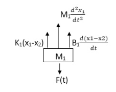
Soln: - The free body diagram for M1 will be
|
F(t) = M1 d2/dt2x1+ B1 d/dt (x1-x2) + k1(x1-x2)
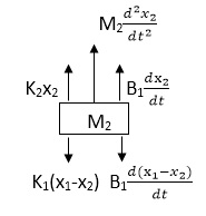
Similarly, for M2we have
|
K1(x1-x2) + B1d/dt(x1-x2) = k2x2+M2d2/dt2+B2dx2/dt
1.4.2 Gear Trains
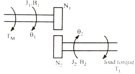
A gear train is a mechanical device that transmits energy from one part of the system to another part with maximum power transfer. Transformers are electrical analogous of gears. For ideal case friction and inertia of gears are neglected. The gear transmitting power with N1 teeth is called primary gear which receives power and gear with N2 teeth is called as secondary gear.
|
Fig 9 Schematic of two gear train
Let angular displacement of gear 1 be  1 and that of gear 2 be
  2. The moment of inertia and viscous friction of gear 1 are denoted by J1 and B1 respectively and moment of inertia and viscous friction of gear 2 are denoted by J2 and B2. Let TM be the motor torque and TL is the load torque. The balance equation on primary side of motor side is
TM = J1 As there is no power loss than T12 T12 = Torque transmitted from gear 1 to 2 Distance travelled along the surface of each gear is same so
The torque for secondary side is given by T21 = J2 TM = J1 Substituting T21 in above equation we get TM = J1 = J1 = [J1+ J2( JLeq = [J1+ J2( BLeq = [B1 + B2( TLeq = |
1.4.3 Electrical Systems
|
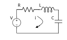
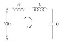
Fig 10 Electrical System
Applying Kirchoff’s voltage Law
V= Ri +Ldi/dt +1/c V= Rdq/dt + L d2q/dt2+q/c Now by kirchoff’s current low I= V/R+ 1/L But V= dø/dt
I= 1/R dø/dt + 1/L ø+cd2ø/dt2 But v= dø/dt I= 1/R dø/dt+ 1/L. ø+c d2ø/dt2 |
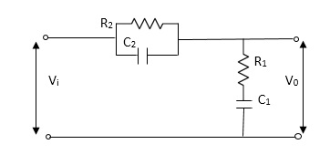
Q2) Find V0(s)/Vi(s)?
|
Sol: Let Z1 = R2 11 1/c2
=R2*1/c2s/R2+1/c2s
Z1= R2/1+R2c2s
Let Z2 = R1+1/c1s
Z2= 1+R1c1s/c1s V0(s)/vi(s) = z2/z1+z2 = 1+R1c1s/c1s/R2/1+R2c2s+1+R1c1s/c1s V0(s)/v0(s) =(c1+R1c1s) (1+R2c2s)/R2c1s+1+sR1c1s2R1R2c1c2 |
1.4.4 Friction
The friction exists in physical systems whenever mechanical surfaces are operated in sliding contact. The friction can be
i) Coulomb Friction Force: This is the force of sliding friction between dry surface and is normally constant.
ii) Viscous Friction Force: The force between a solid body and a fluid medium is called as viscous friction force.
iii) Stiction: The force required to initiate motion between two contacting surfaces.
Key Takeaway
- The frictional force acts in opposite direction to that of velocity. Some times friction is necessary in the physical system in order to improve the dynamic response of the system.
1.4.4 Analogous Systems
Electrical and mechanical systems possess fixed analogy and there exist similarity between the equilibrium equations of the two. This allows forming such electrical systems whose behavioural characteristics are similar to the given mechanical system. Such systems are known as analogous systems.
Basically, two systems are analogous in nature when the conditions given below are fulfilled:
1 . There must be two physically different systems.
2 There should have the same differential equation modelling of the systems.
The electrical analogous of mechanical translational can be obtained by
i) Force-Voltage Analogy (Loop Analysis)
ii) Force-Current Analogy (Node Analysis)
i) Force-Voltage Analogy: If the dynamic characteristics of an electrical system is identical to that of a mechanical system, then the electrical system is said to be analogous to the mechanical system. This can be done by comparing the mathematical models of both the systems.
|
Fig 11 Mechanical System
The equation for above mechanical system is given by
f(t) = M  +B
+B  +kx (1)
For series RLC circuit the mathematical equation is given as
|
Fig 12 Electrical System
V(t)= Ri + L i = V(t) = L
Comparing 1 and 2 we see that
|
This is shown in below table.
ii) Force-Current Analogy:
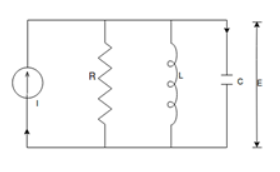
For parallel RLC circuit shown below the KCL equation is written as
|
Fig 13 Electrical Circuit
i(t) = C  +
+  +
+ 
v = 
i(t) = C  + R
+ R +
+  (3)
(3)
Comparing 1 and 3 we find that
 F(t) i(t)
 M C
M C
 x
x 
 B 1/R
B 1/R
 k 1/L
k 1/L
Electrical analogous to mechanical rotational systems
i) Torque-Voltage Analogy: Consider a mechanical rotational system as shown below
|
Fig 14 Mechanical system
The differential equation is then given by
T= J  + B
+ B + k
+ k (4)
(4)
And we already know the equation for series RLC circuit as in equation 2
V(t) = L  + R
+ R +
+ 
Comparing above equation 2 and 4 we have


 T v
T v
 q
q
 i
i
 B R
B R
 J L
J L
 K 1/C
K 1/C
This is shown in below table.
ii)Torque-Current Analogy: Consider the parallel RLC circuit as shown in above section. The equation for the circuit is already known to us given in (3)
i(t) = C  + R
+ R +
+ 
Comparing this equation with (4)
 T i
T i
 J C
J C
 B 1/R
B 1/R
 k 1/L
k 1/L
 v
v
 This is shown in table below.
Key takeaway
Analogy Between Electrical and Mechanical System:
Force -voltage | Force -current | Mechanical Translatory | Mechanical Rotational |
1.Voltage (v) | current | Force (f) | Torque (T) |
2.Charge(q) | Flux (ø) | Displacement(x) | Angular Displacement(ø) |
3.current. | voltage | Velocity v(t) | Angular velocity(w) |
4.Inductance(l) | Capacitance(c) | Mass (m) | Moment of inertia (J) |
5. Resistance(R) | Conductance G= (1/R) | Damping coefficient (B) | Damping Coefficient (B) |
6.Reciprocal of capacitance(1/c) | Inverse of Inductance (1/L) | Stiffness (K) | Stiffness(K) |
1. “Modern Control Engineering “, K. Ogata, Pearson Education Asia/
PHI, 4th Edition, 2002.
2. “Automatic Control Systems”, Benjamin C. Kuo, John Wiley India
Pvt. Ltd., 8th Edition, 2008.
3. “Feedback and Control System”, Joseph J Distefano III et al.,
Schaum’s Outlines, TMH, 2nd Edition 2007.
4. J. Nagarath and M. Gopal, “Control Systems Engineering”, New Age
International (P) Limited, Publishers, Fourth edition – 2005
