UNIT -2
Block Diagrams and Signal flow graphs
It is the ratio of Laplace transform of the output to Laplace transform of input with all initial conditions zero.
|
Fig 1 System with Transfer Function G(s)
Poles and zero of a Transfer Function:
The transfer function can be represented by the ratio of two polynomials
G (S) = a0sn+a1 sn-1-------+an/b0sm+b1sm-1+-----+bn
a0—an ---- constants
G(S) = K(s+z1) (s+z2) (as2+bs+c)/(S+A) (s+p2) (As2+Bs +c)
K= a0/b0 ( Gain of system)
For poles –They are the values of s for which
G(S)
(S+p1)(S+p2)(A
S= p1, -p2 , -B± B2-4Ac/2A
For ZEROS – They are the values of s for which
G(S)
S=-z1, -z2 , -b± b2-4ac/2a
- Location of poles and zeros in s place determines the reliability of the system
- There can be multiple poles and zeros
- The numerator of transfer function when equalized to zero gives zero of system
- The denominator of transfer function which equalized to zero gives poles of system.
Key takeaways
- The numerator of transfer function when equalized to zero gives zero of system.
- The denominator of transfer function which equalized to zero gives poles of system.
Advantages of Block diagram reduction technique:
- Very simple to Construct the Block diagram of complicated electrical & mechanical systems.
- The function of individual element can be visualized form block diagram
- Individual as well as overall performance of the system can be studied by the figure shown in Block diag.
- Overall CLTF can be easily calculated by Block diagram reduction rules.
Disadvantages of Block diagram reduction technique:
It does not include any information above physical construct of system (completely mathematical approach).
- Source of energy in generally not shown in the block diagram so w.g diff. block diagram can be drawn for the same function
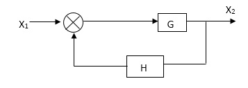
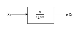
CLTf: -ve feedback
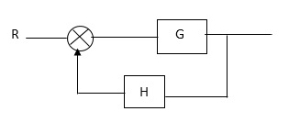
C(s)/R(s)= G(s)/1+G(s)H(s)
CLTF:-+vefeedback
C(S)/R(S) = G(S)/1-G(s)H(S)
Rules of Block diagram Algebra:
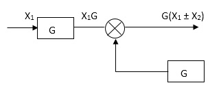
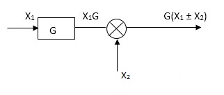
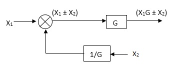
Moving summing point ahead of block
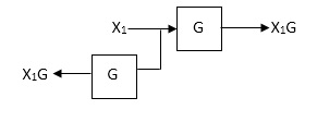
Moving take off point after a block
|
Moving take off point ahead a block
|
Eliminating a feedback Loop
|
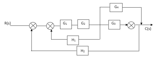
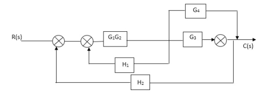
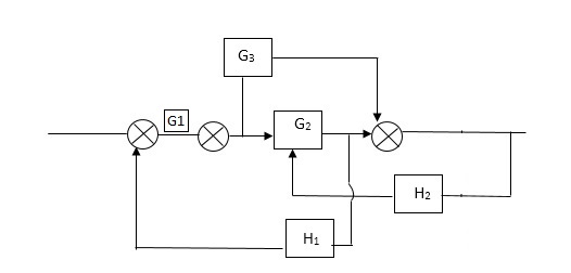
Q. Reduce given B.D to canonical (simple form) and hence obtain the equivalent Tf = c(s)/ R(S)?


|


 Sol:-
Sol:-
|
|
|
|
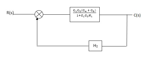
C(S)/R(S) = (G1G2) (G3+G4)/1+G1G2H1)/1-G1,G2(G3+G4) H2/1+G1G2H1 = G1G2(G3+G4)/1+G1G2H1-G1G2H2(G3+G4) =G1G2(G3+G4)/1+(H1-H2)(G1G2) (G3+G4) C(s)/R(S) = G1G2(G3+G4)/1+(H1-H2(G3+G4)) G1 G2
|
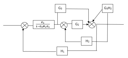
Reduce the Block diagram
|


|
|
|
|


|


|
|
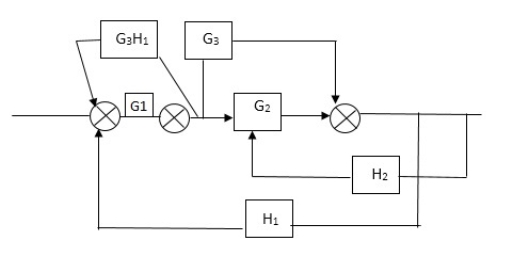
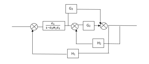
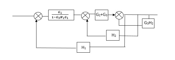
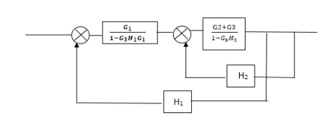
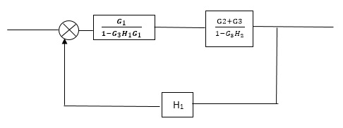
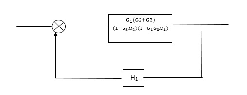
C(s)/R(s)= G1(G3+G2)/(1-G1G3X1) (1-G2X2) H1 = G(G3+G2)/(1-G3G1H1) (1-G2H2) + G1H1(G3+G2) = G1(G3+G2)/1-G3G1H1-G2H2+G1H1(G3+G2H1 =G1(G3+G2)/1-G3H2+G1G2H1(1+G3H2)
|


|
Block Diagram
|
SFG
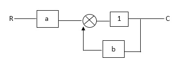
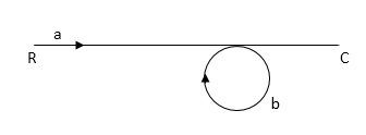
Q: Draw SFG for the following block diagram?
|
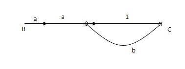
Sol:
| |
|
Ra+cb =c
c/R= a/1-b
RULES:
1) The signal travels along a branch in the direction of an arrow.
2) The input signal is multiplied by the transmittance to obtain the o/p.
3) I/p signal at a node is sum of all the signals entering at that node.
4) A node transmits signal at all branches leaving that node.
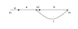
Q. The SFG shown has forward path and singles isolated loop determine overall transmittance relating X3 and X1
|
Soln:
X1- I/p node
X2-Intenmediale node
X3- o/p node
ab- forward path (p)
bc- 1 loop (L)
At node XQ:
X2 = x1a + x3c [Add i/p signals at node] At node x3: x2b =x3 (x1a+x3c) b = x3 X1ab = x3 (1-bc) X1 = x3 (1-bc)/ab Ab/(1-bc) = x3/x1 T= p/1-L |
|
X1:- I/p node x2, x3,x4,x5,Qnlexmedili node X0:- o/p node abdeg:- forward path bc, ef :- Loop [isolated] x2 = ax1+c x3 x3= bx2 x4 = d x3+f x5 x5 = e x4 x6= g x5 x6 = g(e x4) = ge [dx3+ e f x5] xb = ge [d (bx2) + f (e x4)] xb = ge [ db (ax1+cx3) + fe (dx3+ fx5)] xb = ge [db (ax1+cb (ax1+x3) +fe[cdbx2]+ f( e [db (ax1+ cx3) x2 = ax1 + cb (x2) x4 = d bx2 + f exq x2 = ax1 + cbx2 = db (d4) + fe/1-cb x2 = ax1/(1-cb) xy = db x2 + f x6/g xy = db [ax1]/1-cb + f xb/g x5 = c db ( ax1)/1-cb + efxb/g xb = gx5 = gedb (ax1)/1-cb + g efxb/g Xb = gx5 gedb (ax1)/1-cb + g efxb/g (1- gef/g) xb = gedb ax1/1-ab Xb/x1 = gedb a/ (1- ef – bc + beef Xb/x1 = p/ 1- (L1+L2) + L1 L2 for isolated loops
|
Key takeaways
- The function of individual element can be visualized from block diagram
- The signal travels along a branch in the direction of an arrow.
- The input signal is multiplied by the transmittance to obtain the o/p.
Reference
1. “Modern Control Engineering “, K. Ogata, Pearson Education Asia/
PHI, 4th Edition, 2002.
2. “Automatic Control Systems”, Benjamin C. Kuo, John Wiley India
Pvt. Ltd., 8th Edition, 2008.
3. “Feedback and Control System”, Joseph J Distefano III et al.,
Schaum’s Outlines, TMH, 2nd Edition 2007.
4. J. Nagarath and M.Gopal, “Control Systems Engineering”, New Age
International (P) Limited, Publishers, Fourth edition – 2005


