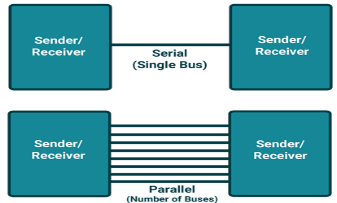
In parallel mode data bits are transferred faster using more data pins. But when comes to a Microcontroller, we cannot afford to dedicate many pins for data transfer. UART or Serial communication in 8051 microcontroller will allow the controller to send and receive data’s by using two pins
|
Figure1. Data Communication
SBUf is physically two registers. One is write only and is used to hold data to be transmitted out of the 8051 via TXD. The other is read only and holds received data from external sources via RXD. Both mutually exclusive registers use address 99h.
There are four programmable modes for serial data communication that are chosen by setting the SMX bits in SCON. Baud rates are determined by the mode chosen.
SCON Register
It a bit addressable register used to set the mode in which serial communication takes place in the controller. The above figure shows the configuration of the SCON register.
|
SM0, SM1: Serial Mode control Bits
SM2: Multiprocessor mode control bit, logic 1 enables Multi processor mode and 0 for normal mode.
SM0, SM1: Serial Mode control Bits
SM2: Multiprocessor mode control bit, logic 1 enables Multi processor mode and 0 for normal mode.
It is defined as number of bits transmitted or received per second and usually expressed in Bits per second bps. For mode 0 and mode 2 the baud rate is determined by means of 1/12, 1/32 or 1/64 of crystal frequency whereas for mode 1 and 3 it is determined by means of timer 1.
|
8 bit register that holds the data that need to be transmitted or the data that is received recently. The serial port of 8051 is full duplex so the microcontroller can transmit and receive data using the register simultaneously.
#include<reg51.h>
void initialize() // Initialize Timer 1 for serial communication
{
TMOD=0x20; //Timer1, mode 2, baud rate 9600 bps
TH1=0XFD; //Baud rate 9600 bps
SCON=0x50;
TR1=1; //Start timer 1
}
void receive() //Function to receive serial data
{
unsigned char value;
while(RI==0); //wait till RI flag is set
value=SBUF;
P1=value;
RI=0; //Clear the RI flag
}
void transmit() // Funtion to transmit serial data
{
SBUF='o'; //Load 'o' in SBUF to transmit
while(TI==0); //Wait till TI flag is set or data transmission ends
TI=0; //Clear TI flag
SBUF='k';
while(TI==0);
TI=0;
}
void main()
{
while(1)
{
initialize();
receive();
transmit();
}
}
Key Takeaway:
Data is transmitted both way at the same time. Half Duplex: Data is transmitted one way at a time. Asynchronous serial communication is widely used for character-oriented (1 byte) transmissions.
|
Fgure 2. Serial Communication
Serial communication means to transfer data bit by bit serially at a time, whereas in parallel communication, the number of bits that can be transferred at a time depends upon the number of data lines available for communication.
Two methods of serial communication are
- Synchronous Communication: Transfer of bulk data in the framed structure at a time
- Asynchronous Communication: Transfer of a byte data in the framed structure at a time
8051 has built-in UART with RXD (serial data receive pin) and TXD (serial data transmit pin) on PORT3.0 and PORT3.1 respectively.
Asynchronous serial communication is widely used for byte-oriented transmission.
Frame structure in Asynchronous communication:
- START bit: It is a bit with which serial communication starts and it is always low.
- Data bits packet: Data bits can be 5 to 9 bits packet. Normally we use 8 data bit packet, which is always sent after the START bit.
- STOP bit: This is one or two bits. It is sent after the data bits packet to indicate the end of the frame. The stop bit is always logic high.
In an asynchronous serial communication frame, the first START bit followed by the data byte and at last STOP bit forms a 10-bit frame. Sometimes the last bit is also used as a parity bit.
|
Figure38051 Serial Frame Structure
Data transmission rate
The data transmission rate is measured in bits per second (bps). In the binary system, it is also called a baud rate (number of signal changes per second). Standard baud rates supported are 1200, 2400, 4800, 19200, 38400, 57600, and 115200. Normally most of the time 9600 bps is used when speed is not a big issue.
Key Takeaways:
Serial Communication uses only two data pins to establish communication between Microcontroller and external devices. In this mode of communication data is transferred one bit at a time
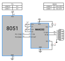
Figure4 .Interface standard
- 8051 serial communication has TTL voltage level which are 0 v for logic 0 and 5 v for logic 1.
- In computers and most of the old devices for serial communication, RS232 protocol with DB9 connector is used. RS232 serial communication has different voltage levels than 8051 serial communication. i.e. +3 v to +25 v for logic zero and -3 v to -25 v for logic 1.
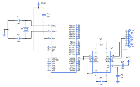
- To communicate with RS232 protocol, we need to use a voltage level converter like MAX232 IC.
- Although there are 9 pins in the DB9 connector, we do not need to use all the pins. Only 2nd Tx(Transmit), 3rd Rx(Receive), and 5th GND pin need to be connected.
Key Takeaways:
The 8051 microcontroller sends and receives data through RS232 interface. RS232 uses MAX232 as a level converter, since standard serial interfacing of microcontroller (TTL) with RS232C Standard device, requires TTL to RS232 Level converter.
Assume that the 8051 serial port is connected to the COM port of IBM PC, and on the PC, we are using the terminal.exe program to send and receive data serially. P1 and P2 of the 8051 are connected to LEDs and switches, respectively.
Write an 8051 program to send to PC the message “We Are Ready”,
ORG 0
MOV P2, #0FFH ; make P2 an input port
MOV TMOD, #20H ; timer 1, mode 2
MOV TH1, #0F AH ; 4800 baud rate
MOV SCON , #50H ; 8-bit , 1 stop, REN enabled.
SETB TR1 ; start timer 1
MOV DPTR , # MYDATA ; load pointer for message
H1_CLR : CLR A
MOV A,@A+DPTR ; get character
JZ B_1 ; if last character get out
ACALL SEND ; otherwise call transfer
INC DPTR ; next_one
SJMP H_1 ; stay in loop
B_1: MOV A,P2 ;read data on P2.
ACALL SEND ; transfer data serially
ACALL RECV ; get the serial data
MOV P1,A ; display it on LED’s
SJMP B_1 ; stay in loop indefinitely
------ serial data transfer -----acc has the data--------
SEND: MOV SBUF,A ; load the data
H_2: JNB T1,H_2 ; stay here until the last bit is gone
CLR T1 ; get ready for next char
RET ; return to caller.
--------------- receive data serially in ACC-----------
RECV: JNB R1,RECV ; wait here for char
MOV A,SBUF ; save it in ACC
CLR R1 ; get ready for next character
RET ; return to caller
--------------------------the message------------------------------
MYDATA: DB “We are Ready”,0
END.
C
Configure Timer 1 in auto-reload mode.
Load TH1 with value as per required baud rate e.g. for 9600 baud rate load 0xFD. (-3 in decimal)
Load SCON with serial mode and control bits. e.g. for mode 1 and enable reception, load 0x50.
Start timer1 by setting TR1 bit to 1.
Load transmitting data in the SBUF register.
Wait until loaded data is completely transmitted by polling the TI flag.
When the TI flag is set, clear it, and repeat from step 5 to transmit more data.
Example
Let's Program 8051 (here AT89C51) to send character data “test” serially at 9600 baud rate in mode 1
Program for serial data transmit
/*
* 8051_Serial_UART
* http://www.electronicwings.com
*/
#include <reg51.h> /* Include x51 header file */
void UART_Init()
{
TMOD = 0x20; /* Timer 1, 8-bit auto reload mode */
TH1 = 0xFD; /* Load value for 9600 baud rate */
SCON = 0x50; /* Mode 1, reception enable */
TR1 = 1; /* Start timer 1 */
}
void Transmit_data(char tx_data)
{
SBUF = tx_data; /* Load char in SBUF register */
while (TI==0); /* Wait until stop bit transmit */
TI = 0; /* Clear TI flag */
}
void String(char *str)
{
int i;
for(i=0;str[i]!=0;i++) /* Send each char of string till the NULL */
{
Transmit_data(str[i]); /* Call transmit data function */
}
}
void main()
{
UART_Init(); /* UART initialize function */
String("test"); /* Transmit 'test' */
while(1);
}
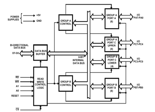
6.6.1 Architecture of 8255A
Figure 5. 8255A architecture
The features of 8255A are as follows −
- It consists of 3 8-bit IO ports i.e. PA, PB, and PC.
- Address/data bus must be externally demux'd.
- It is TTL compatible.
- It has improved DC driving capability.
8255A has three ports, i.e., PORT A, PORT B, and PORT C.
- Port A contains one 8-bit output latch/buffer and one 8-bit input buffer.
- Port B is similar to PORT A.
- Port C can be split into two parts, i.e. PORT C lower (PC0-PC3) and PORT C upper (PC7-PC4) by the control word.
These three ports are further divided into two groups, i.e. Group A includes PORT A and upper PORT C. Group B includes PORT B and lower PORT C. These two groups can be programmed in three different modes, i.e. the first mode is named as mode 0, the second mode is named as Mode 1 and the third mode is named as Mode 2.
8255A has three different operating modes −
- Mode 0 − In this mode, Port A and B is used as two 8-bit ports and Port C as two 4-bit ports. Each port can be programmed in either input mode or output mode where outputs are latched and inputs are not latched. Ports do not have interrupt capability.
- Mode 1 − In this mode, Port A and B is used as 8-bit I/O ports. They can be configured as either input or output ports. Each port uses three lines from port C as handshake signals. Inputs and outputs are latched.
- Mode 2 − In this mode, Port A can be configured as the bidirectional port and Port B either in Mode 0 or Mode 1. Port A uses five signals from Port C as handshake signals for data transfer. The remaining three signals from Port C can be used either as simple I/O or as handshake for port B.
6.6.2 I/O addressing
6.6.3 I/O device interfacing with 8051 using 8255A
Figure 6. Interfacing
The format for the control word format for 8255A is shown in figure above. As per the requirement of the programmer the control word is written into the control word register of 8255A.
Bit D0 :
- Sets Port CLower as input or output port.
- To make Port CLower as input port this bit set to 1.
- To make Port CLower as output port this bit set to 0.
Bit D1:
- Sets Port B as input or output port.
- To make Port B as input port this bit set to 1.
- To make Port B as output port this bit set to 0.
Bit D2:
- This bit for mode selection for the port B.
- If this bit set to 0, the port B will operate in mode 0.
- If this bit set to 1, the port B will operate in mode 1.
Bit D3:
- Sets Port CUpper as input or output port.
- To make Port CUpper as input port this bit set to 1.
- To make Port CUpper as output port this bit set to 0.
Bit D4:
- Sets Port A as input or output port.
- To make Port A as input port this bit set to 1.
- To make Port A as output port this bit set to 0.
Bits D5 and D6 :
- These two bits mainly used for determining the I/O mode of port A.
Therefore, these bits are defined for the various modes of port A as follows.
D6 | D5 | Mode of Port A |
0 | 0 | Mode 0 |
0 | 1 | Mode 1 |
1 | 0 or 1 | Mode 2 |
Bit D7:
This bit specifies either I/O function or bit set/reset function (BSR mode). If this bit set to 1 then the 8255 will work in I/O mode. If this bit set to 0 then the 8255 will work in BSR mode.
Key Takeaways:
The Intel's 8255 is designed for use with Intel's 8-bit, 16-bit and higher capability microprocessors. It has 24 input/output lines which may be individually programmed in two groups of twelve lines each, or three groups of eight lines.
References
- The 8051 Microcontroller and Embedded Systems using Assembly and C by Muhammad Ali Mazidi.
- The 8051 Microcontroller by I. Scott Mackenzie, Raphael C.W Phan
3. 8051 Microcontrollers: Internals, Instructions, Programming, and Interfacing Book by Subrata Ghoshal


