Ohm’s Law
Ohm’s principal discovery was that the amount of electric current through a metal conductor in a circuit is directly proportional to the voltage impressed across it, for any given temperature. Ohm expressed his discovery in the form of a simple equation, describing how voltage, current, and resistance interrelate:
|
In this algebraic expression, voltage (E) is equal to current (I) multiplied by resistance (R). Using algebra techniques, we can manipulate this equation into two variations, solving for I and for R, respectively:
|
Kirchhoff’s laws
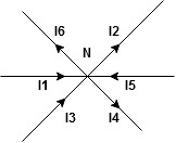
The algebraic sum of currents meeting at a junction or node in a electric circuit is zero or the summation of all incoming current is always equal to summation of all outgoing current in an electrical network.
Explanation
|
Assuming the incoming current to be positive and outgoing current negative we have
I e
|
Kirchhoff’s Voltage Law (KVL)
statement: the algebraic summation of all Voltage in any closed circuit or mesh of loop zero.
i.e. ∑ Voltage in closed loop = 0 the summation of the Voltage rise (voltage sources) is equal to summation of the voltage drops around a closed loop in 0 circuit for explanation from here
determination of sigh and direction of currents (Don’t write in exams just for understanding)
|
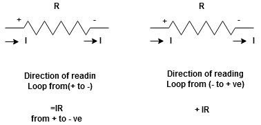
current entering a resistor is +ve and leaving should be –ve
now
|


Potential Rise Potential Drop
|
We are reading from +V to –V we are reading from –V to +V
 potential drops
  potential rise
 -V
-V  +V
+V
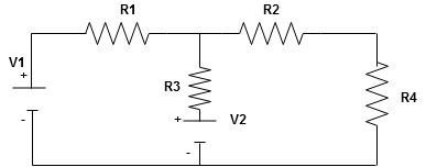
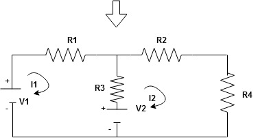
Given Circuit
|
First identify no of loops and assign direction of current flowing in loop
Note: no of loops in circuit = No, of unknown currents = no, of equations in the circuit
|
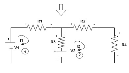
Note: keep loop direction and current direction same ie either clockwise or anticlockwise for all loops I1 I2
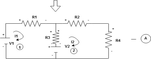
Now according to direction of direction assign signs (+ve to –ve) to the resistors
|
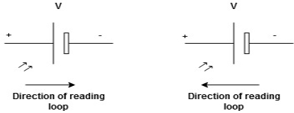
Note: voltage sources (V) polarities does not change is constant.
Note: for common resistor between 2 loops appearing in the circuit like R3 give signs according to separate loops as shown
|
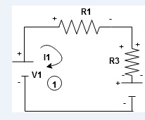
When considering only loop no 1 (+ R3 - )
- B
Now consider diagram A and write equations
Two loops  two unknown currents
  two equation
Apply KVL for loop ① [B. Diagram] (+ to drop -) = - sign and (- to rise +) = + sign
- |
-( ) R2 is considered because in R3,2 currents are flowing
  and
and  and we have taken (
 ) because we are considering loop no 1 and current flowing is
  in loop no 1
 )
)
Similarly for loop no. 2 currents flowing is  resistor R3 it should be
  )R3
)R3
|
Consider loop no. 1 apply KVL - - Consider loop no. 2 apply KVL - - After solving equation ① and ② we will get branch c |
Series and parallel circuit
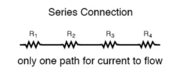
The basic idea of a “series” connection is that components are connected end-to-end in a line to form a single path through which current can flow:
Series connection
|
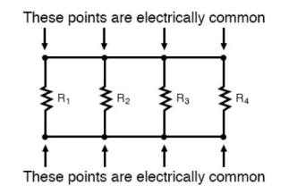
Parallel connection:
The basic idea of a “parallel” connection, on the other hand, is that all components are connected across each other’s leads. In a purely parallel circuit, there are never more than two sets of electrically common points, no matter how many components are connected. There are many paths for current flow, but only one voltage across all components:
|
Current and voltage division rule
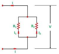
A parallel circuit acts as a current divider as the current divides in all the branches in a parallel circuit, and the voltage remains the same across them. The current division rule determines the current across the circuit impedance. The current division is explained with the help of the circuit shown below:
The current I has been divided into I1 and I2 into two parallel branches with the resistance R1 and R2 and V is the voltage drop across the resistance R1 and R2.
|
As we know,
V = IR ……..(1) | |
Then the equation of the current is written as: I1 = V/R1 and I2 = V /R2 | |
Let the total resistance of the circuit be R and is given by the equation shown below:
R = R1R2/ R1 + R2 |
Equation (1) can also be written as:
I = V/R ……….(3) | |
Now, putting the value of R from the equation (2) in the equation (3) we will get I = V(R1+R2)/ R1R2 ---------------------------(4) | |
But V = I1 R1 = I2 R2 ------------------------------(5) I = I1R1(R1+R2)/ R1R2 = I1(R1+R2)/ R2---------------------(6) And now considering V = I2R2 the equation will be: |
I = I2R2(R1+R2)/ R1R2 = I1/R1 (R1+R2) ------------------------------(7) |
Thus, from the equation (6) and (7) the value of the current I1 and I2 respectively is given by the equation below:
I1 + I . R2/ R1 + R2 and I2 = I . R1 / R1 + R2 |
Thus, in the current division rule, it is said that the current in any of the parallel branches is equal to the ratio of opposite branch resistance to the total resistance, multiplied by the total current.
Voltage Division Rule
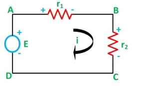
The voltage division rule can be understood by considering a series circuit shown below. In a series circuit, voltage is divided, whereas the current remains the same.
|
Let us consider a voltage source E with the resistance r1 and r2 connected in series across it.
As we know,
I = V/R or we can say I = E/R |
Therefore, the current (i) in the loop ABCD will be: i = E / r1 + r2 -------------------------(8) |
and r1 = ir1
By putting the value of I from equation (8) in equation (9) the voltage across the resistance r1 and r2 respectively are given by the equation shown below as:
E1 = Er1/r1 + r2 and E2 = E r2/ r1 + r2 |
Thus, the voltage across a resistor in a series circuit is equal to the value of that resistor times the total impressed voltage across the series elements divided by the total resistance of the series elements.
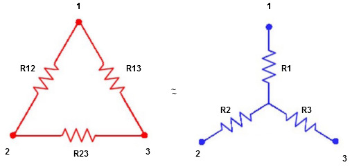
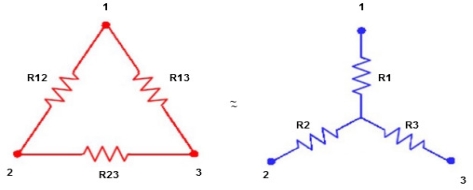
Star to delta conversion to the final equivalent resistance
|
We know that (from delta to star conversion) R1 =
R2 =
R1 =
Multiply ① X ② L.H.S and R.H.S
R1 R2 = |
Similarly, multiply ② X ③
R2 R3 =
And ③ X①
R1 R3 =
Now add equation ④, ⑤, and ⑥ L.H.S and R.H.S
(Delta) Similarly, R23 = R2+R3 +
R23 = R1+R2 + |
Delta to Star Conversion to Find (Req.)
|
Delta = R12// (R23 + R13) =R1 + R2
=
= Here let R = R12 + R23 + R13
=
Now the 3 equations after equating L.H.S. and R.H.S R1 + R2 =
R2 + R3 =
| ||
R1 + R3 =
Now subtract ② and ① on L.H.S. and R.H.S
R2+ R3 – R1 – R2 =
Now add equation ④ and ③
R3 – R1 + R1 + R3 =
2R3 =
Similarly, R1 =
And R2 = R23 R12/R where R = R12 + R23 + R13 i.e. star equivalent from delta network is the ratio of the product of adjacent branches in the delta to the addition of all branches in the delta. | ||
In the field of electrical, single phase supply is the delivery of AC power by a system in which all the supply voltages change in simultaneously. This type of power supply sharing is used when the loads (home appliances) ate generally heat and lighting with some huge electric motors. When a single phase supply is connected to an AC motor doesn’t generate a rotating magnetic field, single phase motors require extra circuits for working, but such electric motors are rare over in rating of 10 kW. In every cycle, a single phase system voltage achieves a peak-value two times; the direct power is not stable.
|
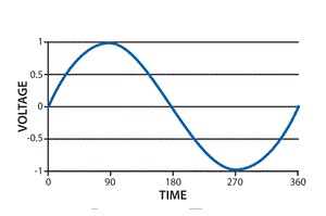
Single Phase Waveform
A load with single-phase can be power-driven from a three-phase sharing transformer in two techniques. One is with the connection between two phases or with connection among one phase and neutral. These two will give dissimilar voltages from a given power supply. This type of phase supply provides up to 230V. The applications of this supply mainly use for running the small home appliances like air conditioners, fans, heater, etc.
Single Phase Supply Benefits
The benefits of choosing a single phase supply include the following.
- The design is less complex
- Design cost is less
- Most efficient AC power supply for up to 1000 watts
- Single Phase AC Power Supply is most competent for up to 1000 watts.
- Wide-range of application uses
Single Phase Supply Applications
The applications of single-phase supply include the following.
- This power supply is applicable for homes as well as businesses.
- Used to supply plenty of power for homes, as well as nonindustrial businesses.
- This power supply is sufficient to run the motors up to about 5 horsepower (hp).
The two factors are related as per the following formula – Generator Frequency (f) = Number of revolutions per minute of the engine (N) * Number of magnetic poles (P) / 120 Conversely, P = 120*f/N
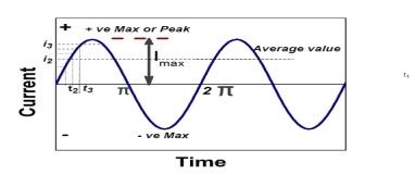
Definition: The average of all the instantaneous values of an alternating voltage and currents over one complete cycle is called Average Value.
If we consider symmetrical waves like sinusoidal current or voltage waveform, the positive half cycle will be exactly equal to the negative half cycle. Therefore, the average value over a complete cycle will be zero.
|
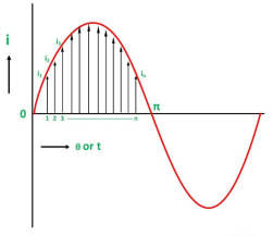
Divide the positive half cycle into (n) number of equal parts as shown in the above figure
Let i1, i2, i3…….. in be the mid ordinates
The Average value of current Iav = mean of the mid ordinates
|
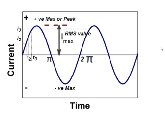
The RMS value of AC current is equal to the steady state DC current that required to produce the same amount of heat produced by ac current provided that resistance and time for which these currents flows are identical
I rms =
Direction for RMS value: Instantaneous current equation is given by i = Im Sin but I rms = | ||
= = = Solving = = Similar we can derive V rms=
| ||
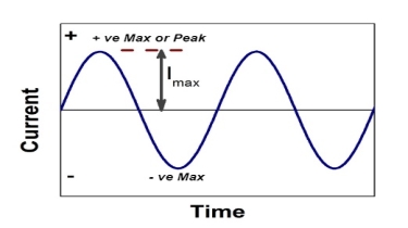
maximum value of alternating current.
|
Peat to peak value:
The value of an alternating quantity from its positive peak to negative peak
|
Average Value:
|
The arithmetic mean of all the value over complete one cycle is called as average value
For the derivation we are considering only hall cycle. Thus i = Im Sin
Solving We get
|
Similarly, Vavg=
The average value of sinusoid ally varying alternating current is 0.636 times maximum value of alternating current.
3 Basic element of AC circuit.
1] Resistance
2] Inductance
3] Capacitance
Each element produces opposition to the flow of AC supply in a forward manner.
Reactance
It is opposition to the flow of an AC current offered by the inductor. XL = ω L But ω = 2 ᴫ F
It is measured in ohm
2. Capacitive Reactance (Xc) It is opposition to the flow of ac current offered by the capacitor Xc = Measured in ohm
|
Impedance (Z)
The ac circuit is to always pure R pure L and pure C it well attains the combination of these elements. “The combination of R1 XL and XC is defined and called as impedance represented as Z = R +i X Ø = 0
R = Resistance, i = denoted complex variable, X =Reactance XL or Xc
Polar Form Z = Where |
 Measured in ohm
Power factor (P.F.)
|
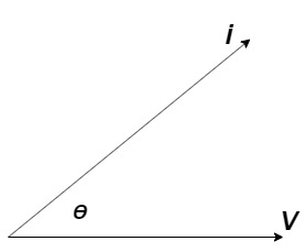
It is the cosine of the angle between voltage and current

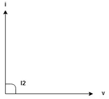
If Ɵis –ve or lagging (I lags V) then lagging P.F.
If Ɵ is +ve or leading (I leads V) then leading P.F.
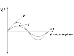
If Ɵ is 0 or in-phase (I and V in phase) then unity P.F.
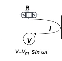
Ac circuit containing pure resisting
|
Consider Circuit Consisting pure resistance connected across the ac voltage source V = Vm Sin ωt ① According to ohm’s law i = But Im =
Phases diagram |
From ① and ② phases or represents RMD value.
|
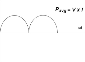
Power P = V. i Equation P = Vm sin ω t Im sin ω t P = Vm Im Sin2 ω t P =
Constant fluctuating power if we integrate it becomes zero
Average power |
Pavg = Pavg = Pavg = Vrms Irms
|
Power ware form [Resultant]
|
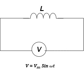
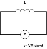
Ac circuit containing pure Inductors
|
Consider pure Inductor (L) is connected across alternating voltage. Source V = Vm Sin ωt |
When an alternating current flow through inductance it setups alternating magnetic flux around the inductor.
This changing the flux links the coil and self-induced emf is produced
According to faradays Law of E M I e = at all instant applied voltage V is equal and opposite to self-induced emf [ Lenz's law] V = -e
But V = Vm Sin ωt
Taking integrating on both sides
| ||
but sin (–
And Im=
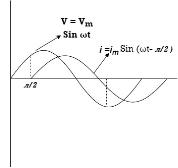
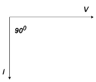
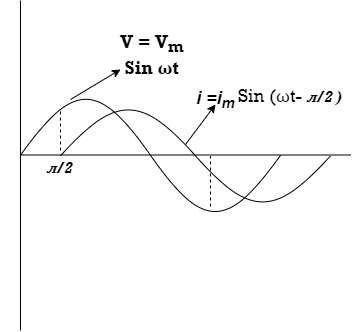
= -ve = lagging = I lag v by 900 | ||
Waveform:
|
Phasor:
|
Power P = Ѵ. I = Vm sin wt Im sin (wt = Vm Im Sin wt Sin (wt –
And Sin (wt - Sin (wt –
The average value of sin curve over a complete cycle is always zero |
|
Ac circuit containing pure capacitors:
|
Consider pure capacitor C is connected across an alternating voltage source
Ѵ = Ѵm Sin wt |
Current is passing through capacitor the instantaneous charge ɡ produced on the plate of the capacitor
ɡ = C Ѵ ɡ = c Vm sin wt |
the current is the rate of flow of charge
i = c Vm w cos wt then rearranging the above eqth. i =
i = but
|
= leading
= I leads V by 900
Waveform:
|
Phase
|
Power P= Ѵ. i = [Vm sinwt] [ Im sin (wt + X/2)] = Vm Im Sin wt Sin (wt + X/2)]
| ||
| ||
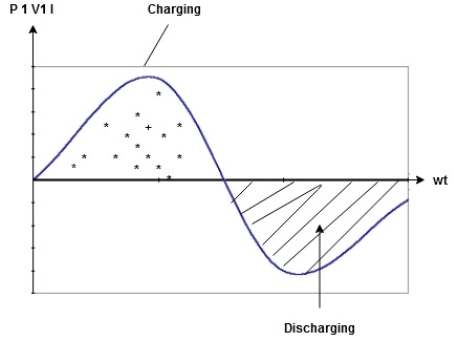
 to charging power waveform [resultant].
|


