Transformers (sometimes called "voltage transformers") are devices used in electrical circuits to change the voltage of electricity flowing in the circuit. Transformers can be used either to increase the voltage (called "stepping up") or decrease the voltage ("step down").
Energy is lost in the process of transmitting electricity long distances, such as during the journey from a power plant to your home. Less energy is lost if the voltage is very high, so electrical utilities use high voltage in long-distance transmission wires. However, this high voltage is too dangerous for home use. Electrical utilities use transformers to change the voltage of electricity as it travels from the power plant to you. First, the voltage of electricity coming from the power plant is "stepped up" using transformers to the right level for long-distance transmission. Later, the voltage is stepped down before it enters your home - once again using transformers.
In order for the electrical power distribution network to function, voltages must be stepped up before power is transmitted great distances over power lines. One major problem is that power is lost between the power plant and the consumers because currents use some of the power to heat the transmission lines. The power transmitted along the line is equal to the voltage times the current. The higher the voltage the lower the current that must flow within the transmission lines to deliver the same power. Lower currents produce much less heating and much less power loss. Of course, the high voltages (needed to drive the low currents) must be stepped back down before power is supplied to our homes. Transformers are the critical elements that step up and down the voltages at each end of the line.
Transformers are often used in electrical circuits to change the voltage of electricity flowing through a circuit. The coils of wire on each side of the transformer have different numbers of turns, causing the voltage out to be different from the voltage in.
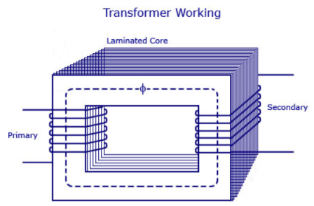
The main principle of operation of a transformer is mutual inductance between two circuits which is linked by a common magnetic flux. A basic transformer consists of two coils that are electrically separate and inductive, but are magnetically linked through a path of reluctance. The working principle of the transformer can be understood from the figure below.
|
As shown above the electrical transformer has primary and secondary windings. The core laminations are joined in the form of strips in between the strips you can see that there are some narrow gaps right through the cross-section of the core. These staggered joints are said to be ‘imbricated’. Both the coils have high mutual inductance. A mutual electro-motive force is induced in the transformer from the alternating flux that is set up in the laminated core, due to the coil that is connected to a source of alternating voltage. Most of the alternating flux developed by this coil is linked with the other coil and thus produces the mutual induced electro-motive force. The so produced electro-motive force can be explained with the help of Faraday’s laws of Electromagnetic Induction as
e=M*dI/dt |
If the second coil circuit is closed, a current flow in it and thus electrical energy is transferred magnetically from the first to the second coil.
The alternating current supply is given to the first coil and hence it can be called as the primary winding. The energy is drawn out from the second coil and thus can be called as the secondary winding.
Types of transformers
Acc to input supply : I phase and  phase
phase
Acc to construction: core and shell type
Acc to 0/P: step up and step down
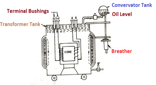
Construction of transformers (study only for MCQs)
|
- Losses in a Transformer [6m]
There are 2 types of losses occurring in a transformer
A) 1. Core loss or Iron loss
B) 2. Copper loss
- Core losses:
- This loss is due to the reversal of flux
- The flux set up in the core is dependent on the i/p supply
 as the i/p supply is constant in magnitude
  the flux set up will be constant and
  core losses are also constant.
 - Core losses are voltage dependent loss they can be subdivided in 2
1 Hysteresis loss
2 reedy current loss
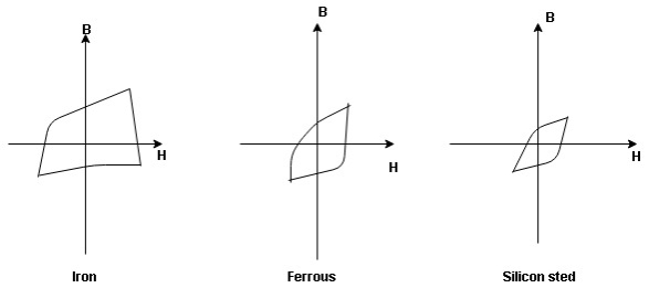
- Hysteresis loss: The iron loss occurring in the core of T/F due to the Hysteresis curve of the magnetic material used for core is called as Hysteresis loss.
Hysteresis curve is the curve as loop which shows the properly of magnetic material to lag the flux density B behind the field Intensely H
|
Above is the 3 different loops (Hysteresis of 3 diff. Materials)
 the selection of magnetic material for the construction of core depends upon Hysteresis loop of that material having tall and narrow Hysteresis loop is selected for the T/F core
 silicon Steel
Hysteresis loss depends on fold factor PH = KH. Bm1.67 F Where KH = constant (Hyst) Bm = max Flux density F = Frequency
|
2. Reedy current loss:
This loss is due to the flow of reedy (circular) current in the core caused by induced emf in core
PE = Ke Bm2 f2 t2 v – watts Where Ke = reedy current const. t = thickness of core |
It can be reduced by using stacks of laminations instead of solid core
B] Copper loss: PCU
The Copper loss is due to resistance of the primary and secondary winding
It is load dependent / current dependent loss
As load on a transformer is variable (changing) Primary secondary Total C is loss = I12R12 + I22 R22 |
copper loss is a variable loss
Copper loss depends upon load on T/F and is proportional to square of load current or KVA rating of transformer
F.L = full load
= (0.5)2 PCU F.L. Or PCu (
|
Find no load vtg E2 remove the load and measure the reading of V2 meter ew will get n load vtg E2
Now connect load and measure V2 this is now the load voltage
For each reading E2 will be same but V2 will change acc. To load
|
|
Efficiency: it is the ratio output power to input power of transformer
Output power = input power – total loss
O/P power = KVA Or = V2 Losses = Pi + PCU (F.L) = iron + copper loss
Maximum efficiency – for numerical: The efficiency of T/F is maximum when copper loss equates iron loss this is the condition for max efficiency ie Pi = PCU
Where KVA at max n given = Full load KVA |
Different Types of Electrical Wiring Systems
The types of internal wiring usually used are
- Cleat wiring
- Wooden casing and capping wiring
- CTS or TRS or PVC sheath wiring
- Lead sheathed or metal sheathed wiring
- Conduit wiring
There are additional types of conduit wiring according to Pipes installation (Where steel and PVC pipes are used for wiring connection and installation).
- Surface or open Conduit type
- Recessed or concealed or underground type Conduit
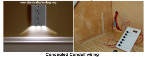
If the conduits are hidden inside the wall slots with the help of plastering, it is called concealed conduit wiring. In other words, the electrical wiring system inside wall, roof or floor with the help of plastic or metallic piping is called concealed conduit wiring. obliviously, it is the most popular, beautiful, stronger and common electrical wiring system nowadays.
|
Find no load vtg E2 remove the load and measure the reading of V2 meter ew will get n load vtg E2
Now connect load and measure V2 this is now the load voltage
For each reading E2 will be same but V2 will change acc. To load |
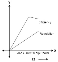
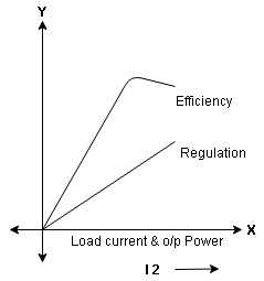
- Form Results Plot graph for efficiency and regulation against I2 and O/P power W2
|
Efficiency: it is the ratio output power to input power of transformer
Output power = input power – total loss
O/P power = KVA Or = V2 Losses = Pi + PCU (F.L) = iron + copper loss
Maximum efficiency – for numerical: The efficiency of T/F is maximum when copper loss equates iron loss this is the condition for max efficiency ie Pi = PCU
| ||
Where KVA at max n given = Full load KVA | ||
It’s vitally important to take safety precautions when working with electricity. Safety must not be compromised and some ground rules need to be followed first. The basic guidelines regarding safe handling of electricity documented below will help you while working with electricity.
1. Avoid water at all times when working with electricity. Never touch or try repairing any electrical equipment or circuits with wet hands. It increases the conductivity of electric current.
2. Never use equipment with frayed cords, damaged insulation or broken plugs.
3. If you are working on any receptacle at your home then always turn off the mains. It is also a good idea to put up a sign on the service panel so that nobody turns the main switch ON by accident.
4. Always use insulated tools while working.
5. Electrical hazards include exposed energized parts and unguarded electrical equipment which may become energized unexpectedly. Such equipment always carries warning signs like “Shock Risk”. Always be observant of such signs and follow the safety rules established by the electrical code followed by the country your in.
6. Always use appropriate insulated rubber gloves and goggles while working on any branch circuit or any other electrical circuit.
7. Never try repairing energized equipment. Always check that it is de-energized first by using a tester. When an electric tester touches a live or hot wire, the bulb inside the tester lights up showing that an electrical current is flowing through the respective wire. Check all the wires, the outer metallic covering of the service panel and any other hanging wires with an electrical tester before proceeding with your work.
8. Never use an aluminum or steel ladder if you are working on any receptacle at height in your home. An electrical surge will ground you and the whole electric current will pass through your body. Use a bamboo, wooden or a fiberglass ladder instead.
9. Know the wire code of your country.
10. Always check all your GFCI’s once a month. A GFCI (Ground Fault Circuit Interrupter) is a RCD (Residual Current Device). They have become very common in modern homes, especially damp areas like the bathroom and kitchen, as they help avoid electrical shock hazards. It is designed to disconnect quickly enough to avoid any injury caused by over current or short circuit faults.
11. Always use a circuit breaker or fuse with the appropriate current rating. Circuit breakers and fuses are protection devices that automatically disconnect the live wire when a condition of short circuit or over current occurs. The selection of the appropriate fuse or circuit breaker is essential. Normally for protection against short circuits a fuse rated of 150% of the normal circuit current is selected. In the case of a circuit with 10 amperes of current, a 15 ampere fuse will protect against direct short circuits whereas a 9.5 amperes fuse will blow out.
12. Working outside with underground cabling can be dangerous. The damp soil around the cable is a good conductor of electricity and ground faults are quite common in the case of underground cabling. Using a spade to dig at the cable can damage the wiring easily so it is better to dig at the cable by hand while wearing insulated gloves.
13. Always put a cap on the hot/live wire while working on an electric board or service panel as you could end up short circuiting the bare ends of the live wire with the neutral. The cap insulates the copper ends of the cable thus preventing any kind of shock even if touched mistakenly.
14. Take care while removing a capacitor from a circuit. A capacitor stores energy and if it’s not properly discharged when removed it can easily cause an electric shock. An easy way to discharge low voltage capacitor is that after removal from the circuit is to put the tip of two insulated screw drivers on the capacitor terminals. This will discharge it. For high voltage ones a 12 Volts light bulb can be used. Connecting the bulb with the capacitor will light up the bulb using up the last of the stored energy.
15. Always take care while soldering your circuit boards. Wear goggles and keep yourself away from the fumes. Keep the solder iron in its stand when not in use; it can get extremely hot and can easily cause burns.
The process of transferring the immediate discharge of the electrical energy directly to the earth by the help of the low resistance wire is known as the electrical earthing. The electrical earthing is done by connecting the non-current carrying part of the equipment or neutral of supply system to the ground.
Electrical Earthing
The process of transferring the immediate discharge of the electrical energy directly to the earth by the help of the low resistance wire is known as the electrical earthing. The electrical earthing is done by connecting the non-current carrying part of the equipment or neutral of supply system to the ground.
Mostly, the galvanised iron is used for the earthing. The earthing provides the simple path to the leakage current. The short-circuit current of the equipment passes to the earth which has zero potential. Thus, protects the system and equipment from damage.
Pipe Earthing:
For earthing house wiring, factory wiring (especially electrical installations of big factories), neutral wire of the supply line etc., galvanized iron pipe is generally used as earth electrode. The size of the pipe depends upon fault current and the condition of the soil. According to Indian Code of Practice if moist and soft soil is available in the earth pit, the length of the pipe should be at least 2 meters and its diameter 38.1 mm.
If the soil is dry and rocky, the length of the pipe should be increased to 2.75 meters. In order that the contact between inner surface of the pipe and the soil is perfect, some holes of diameter 12 mm are made on the pipe at equal intervals along the length.
The pipe is placed upright in the pit as shown in fig. 176. It must be placed in permanently wet ground. The depth at which the pipe should be buried depends upon the condition of the ground moisture.
Plate or Copper Plate Earthing:
In case of plate earthing if galvanized iron plate is used as earth electrode, its size shall not be less than 60 cm x 60 cm x 6.35 mm (2 ft x 2 ft x ½ in) according to Indian Standard. With this plate galvanized iron wire is used as earth lead. If copper plate is used, its size must be at least 60 cm x 60 cm x 3.18 mm (2 ft x 2 ft. x ⅛ in), and copper wire should be used as earth lead with this plate. In both cases plate is kept vertically in the earth pit at a depth of at least 3 meters (10 ft) below ground level.
The depth at which the plate is kept in the earth pit depends upon the condition of the soil. It must be placed in a permanently wet ground. If the soil surrounding the plate becomes dry and hard, the earthing itself becomes a source of danger. For this reason, periodical testing of earthing arrangement is necessary.
