It is known that the electric supply used now-a-days for commercial, as well as domestic purposes, is of alternating type. Similar to d.c machines, the a.c machines associated with alternating voltages, are also classified as generators.
Machines generating ac EMF are called alternators or synchronous generators. While the machines accepting input from a.c supply to produce a mechanical output are called synchronous motors. Both these machines work at a specific constant speed called synchronous speed and hence is general called synchronous machines.
Construction of Synchronous Generator
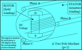
In general, synchronous generator consists of two parts rotor and stator. The rotor part consists of field poles and stator part consists of armature conductors. The rotation of field poles in the presence of armature conductors induces an alternating voltage which results in electrical power generation.
|
Construction of Synchronous Generator
The speed of field poles is synchronous speed and is given by
Ns = 120f/P |
Where, ‘f’ indicates alternating current frequency and ‘P’ indicates number of poles.
Synchronous Generator Working Principle
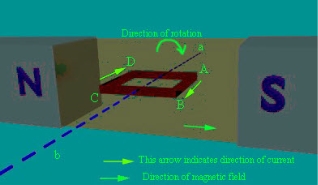
The principle of operation of synchronous generator is electromagnetic induction. If there exists a relative motion between the flux and conductors, then an emf is induced in the conductors. To understand the synchronous generator working principle, let us consider two opposite magnetic poles in between them a rectangular coil or turn is placed as shown in the below figure.
If the rectangular turn rotates in clockwise direction against axis a-b as shown in the below figure, then after completing 90 degrees’ rotation the conductor sides AB and CD comes in front of the S-pole and N-pole respectively. Thus, now we can say that the conductor tangential motion is perpendicular to magnetic flux lines from north to south pole.
|
Direction of Rotation of Conductor perpendicular to Magnetic Flux
So, here rate of flux cutting by the conductor is maximum and induces current in the conductor, the direction of the induced current can be determined using Fleming’s right hand rule. Thus, we can say that current will pass from A to B and from C to D. If the conductor is rotated in a clockwise direction for another 90 degrees, then it will come to a vertical position as shown in the below figure.
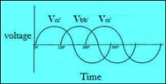
Now, if we consider a practical synchronous generator, then field magnets rotate between the stationary armature conductors. The synchronous generator rotor and shaft or turbine blades are mechanically coupled to each other and rotates at synchronous speed. Thus, the magnetic flux cutting produces an induced emf which causes the current flow in armature conductors. Thus, for each winding the current flows in one direction for the first half cycle and current flows in the other direction for the second half cycle with a time lag of 120 degrees (as they displaced by 120 degrees). Hence, the output power of synchronous generator can be shown as below figure.
|
EMF Equation of Synchronous Generator or Alternator:
We know that Synchronous Generator or Alternator will generate an EMF. The following is the derivation of emf equation of Synchronous Generator or Alternator. Let Φ = Flux per pole, in Wb P = Number of poles N = Synchronous speed in r.p.m f = Frequency of induced emf in Hz Z = Total number of conductors Zph = Conductors per phase connected in series Zph = Z/3 as number of phases = 3 |
Consider a single conductor placed in a slot.
The average value of emf induced in a conductor = dΦ/dt
or one revolution of a conductor,
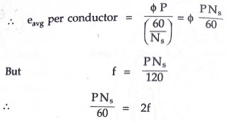
eavg per conductor = (Flux cut in one revolution/Time taken for one revolution)
Total flux cut in one revolution is Φ x P. |
- Principle and working of Synchronous generator or alternator
Time taken for one revolution is 60/Ns seconds.
Substituting in above equation |
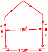
Assume full pitch winding for simplicity i.e. this conductor is connected to a conductor which is 180° electrical apart. So these two emf's will try to set up a current in the same direction i.e. the two emf are helping each other and hence resultant emf per turn will be twice the emf induced in a conductor.
emf per turn = 2 x (emf per conductor) = 2 x (2 f Φ) = 4 f Φ volts. | |||
| |||
Turn of full pitch coil | |||
Let Tph be the total number of turns per phase connected in series. Assuming concentrated winding, we can say that a are placed in single slot per pole per phase (So induced emf's in all turns will be in phase as placed in a single slot. Hence net emf per phase will be algebraic sum of the emf's per turn.
Average Eph = Tph x 4 f Φ |
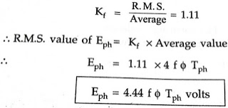
But in ac circuits, RMS value of an alternating quantity is used for the analysis. The form factor is 1.11 of sinusoidal emf.
Consider- 3Ф slip ring I.M
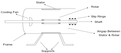
Cut section diagram: -
|
|
The induction motor has following important parts: -
- Stator: - it is the stationary part of induction motor and it is one of important part in induction motor.
- Rotor: - the rotor is the rotating part of induction motor which consists of rotor wdg.
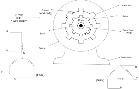
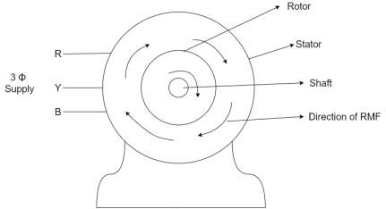
- Stator winding: - this wdg. Is mounted on devastator and it generates the RMF i.e. rotating magnetic field.
- Rotor winding: - rotor winding is used to rotate the shaft of motor. This wdgis provided on rotor
- Frame: - it provides the mechanical support to the motor. It is the outer covering of motor. It protects the internal parts of motor from damage.
- Shaft: - shaft is used to connect to the load and four rotations.
- Slip rings and brushes: - slip rings are mounted on the shaft which is connected with brushes from which connection is given to the external resistant or rheostat
- Cooling fan: - this is provided for cooling purpose of motor and its internal parts.
Principle of operation of induction motor:
|
- When the 3Ф A.C supply is connected across the stator of induction motor, the current starts flowing through the stator wdg. i.e the stator condition.
- Due to this current of flux (Ф) is established in the stator wdg. This flux (Ф) is alternating (changing) in nature. Thus this flux links with the rotor also, and a Rotating Magnetic Field (RMF) is produced.
- This flux (Ф) induces in the rotor also. The RMF is produced in the air gap between stator and rotor.
- The rotor is rotating part which is till stationary, show the rotating magnetic field is cut by stationary rotor and an EMF is induced in the rotor winding. According to faraday's law of EMI the rotor EMF gives the rise to rotor current which opposes the main cause producing it according Lenz's law.
Types of induction motor:
Two main types depending upon the rotor
- Squirrel cage induction motor (squirrel cage rotor)
- Slip ring induction motor (slip ring or wound rotor)
Induction motor are also available in 1Ф supply i.e.
1. Resistance split phase induction motor
2. Capacitor start induction motor
3. Capacitor start capacitor run induction motor
4. 1Ф induction motor i.e. A.C series motors
5. Shaded pole induction motor
Torque equation of induction motor: -
Torque produced in induction motor depends upon the following factors
1.The rotor power factors ( CosФ) under running condition
2.The rotor current under running condition
3. The part of RMF which induces EMF in rotor wdgi.e. flux (Ф)
We can mathematically say that,
But in case of induction motor Suffix 1 -> used for stator/stator parts (qty) Suffix 2-> used for rotor/rotor parts(qty)
Therefore,
But,
Transformation ratio i.e. given by Therefore,
| ||
And also Hence i.e.
4 Substract (3) and (4) into (1) equation we get,
At starting condition slip S=1 So, | ||
