Civil Engineering is that field of engineering concerned with planning, design and construction for environmental Control, development of natural resources, buildings, transportation facilities and other structures required for health, welfare, safety, employment and pleasure of mankind"
The main scope of civil engineering or the task of civil engineering is planning, designing, estimating, supervising construction, managing construction, execution, and maintenance of structures like building, roads, bridges, dams, etc. ' One who designs and maintains works of public utility is known as civil engineer. Civil engineer should have qualities like scientific attitude, imaginative and intuitive approach; He should have good analysis and decisive power. He should be able to solve engineering problems, by using mathematical modeling, scientific principles and laboratory techniques using computer and information technology. He should be able to use operation research techniques for solution of management problems.
Branches in civil engineering
Civil engineering is the design, implementation, and maintenance of public works. This involves facilities and structures such as arenas, large scale monuments, government buildings, transportation routes as well as other structures. Engineers will either work for the city or for a private firm that has been hired by the city. Some civil engineers work in the private sector on projects for independent companies. There are several types of civil engineering. A civil engineer can specialize in a number of different civil engineering branches. Those branches are described briefly below:
- Structural Engineering
- Geotechnical Engineering
- Environmental Engineering
- Transportation Engineering
- Water Resource Engineering
- Earthquake Engineering
- Material Engineering
- Construction Engineering
- Surveying
- Municipal Engineering
- Coastal Engineering
- Tunnel Engineering
Scope of Civil Engineering Civil engineering is the oldest branch of engineering which is growing right from the stone age of civilization. American society of civil engineering defines civil engineering as the profession in which a knowledge of the mathematical and physical sciences gained by study, experience and practice is applied with judgment to develop ways to utilize economically the materials and forces of the nature for the progressive well being of man.
Surveying:
The two principles are
1. LOCATION OF A POINT BY MEASUREMENT FROM TWO POINTS OF REFERENCE:
The relative positions of the points to be surveyed should be located by taking measurement from at least two points of reference. Points of reference are points whose position is already fixed
2. SECOND PRINCIPLE IS TO WORK FROM WHOLE TO PART:
It is very essential to establish first a system of control points and to fix them with higher precision. Minor control points can be established by less precise methods and the details can be located using these minor control points by running minor traverses.
CLASSIFICATION OF SURVEYING
Generally, surveying is divided into two major categories: plane and geodetic surveying
PLANE SURVEYING
PLANE SURVEYING is a process of surveying in which the portion of the earth being surveyed is considered a plane. The term is used to designate survey work in which the distances or areas involved are small enough that the curvature of the earth can be disregarded without significant error. In general, the term of limited extent. For small areas, precise results may be obtained with plane surveying methods, but the accuracy and precision of such results will decrease as the area surveyed increases in size. To make computations in plane surveying, you will use formulas of plane trigonometry, algebra, and analytical geometry.
GEODETIC SURVEYING
GEODETIC SURVEYING is a process of surveying in which the shape and size of the earth are considered. This type of survey is suited for large areas and long lines and is used to find the precise location of basic points needed for establishing control for other surveys. In geodetic surveys, the stations are normally long distances apart, and more precise instruments and surveying methods are required for this type of surveying than for plane surveying.
TOPOGRAPHIC SURVEYS
The purpose of a TOPOGRAPHIC SURVEY is to gather survey data about the natural and man-made features of the land, as well as its elevations. From this information a three-dimensional map may be prepared. You may prepare the topographic map in the office after collecting the field data or prepare it right away in the field by plane table. The work usually consists of the following:
1. Establishing horizontal and vertical control that will serve as the framework of the survey
2. Determining enough horizontal location and elevation (usually called side shots) of ground points to provide enough data for plotting when the map is prepared
3. Locating natural and man-made features that may be required by the purpose of the survey
4. Computing distances, angles, and elevations
5. Drawing the topographic map
Topographic surveys are commonly identified with horizontal and/or vertical control of third-and lower-order accuracies.
ROUTE SURVEYS
The term route survey refers to surveys necessary for the location and construction of lines of transportation or communication that continue across country for some distance, such as highways, railroads, open-conduit systems, pipelines, and power lines. Generally, the preliminary survey for this work takes the form of a topographic survey. In the final stage, the work may consist of the following:
1. Locating the center line, usually marked by stakes at 100-ft intervals called stations
2. Determining elevations along and across the center line for plotting profile and cross sections
3. Plotting the profile and cross sections and fixing the grades
4. Computing the volumes of earthwork and preparing a mass diagram
5. Staking out the extremities for cuts and fills
6. Determining drainage areas to be used in the design of ditches and culverts
7. Laying out structures, such as bridges and culvert
8. Locating right-of-way boundaries, as well as staking out fence lines, if necessary
SPECIAL SURVEYS
SPECIAL SURVEYS are conducted for a specific purpose and with a special type of surveying equipment and methods. A brief discussion of some of the special surveys familiar to you follows.
Land Surveys
LAND SURVEYS (sometimes called cadastral or property surveys) are conducted to establish the exact location, boundaries, or subdivision of a tract of land in any specified area. This type of survey requires professional registration in all states. Presently, land surveys generally consist of the following chores:
1. Establishing markers or monuments to define and thereby preserve the boundaries of land belonging to a private concern, a corporation, or the government.
2. Relocating markers or monuments legally established by original surveys. This requires examining previous survey records and retracing what was done. When some markers or monuments are missing, they are reestablished following recognized procedures, using whatever information is available.
3. Rerunning old land survey lines to determine their lengths and directions. As a result of the high cost of land, old lines are re-measured to get more precise measurements.
4. Subdividing landed estates into parcels of predetermined sizes and shapes.
5. Calculating areas, distances, and directions and preparing the land map to portray the survey data so that it can be used as a permanent record. 6. Writing a technical description for deeds.
Control Surveys
CONTROL SURVEYS provide "basic control" or horizontal and vertical positions of points to which supplementary surveys are adjusted. These types of surveys (sometimes termed and traverse stations and the elevations of bench marks. These control points are further used as References for hydrographic surveys of the coastal waters; for topographic control; and for the control of many state, city, and private surveys.
Horizontal and vertical controls generated by land (geodetic) surveys provide coordinated position data for all surveyors. It is therefore necessary that these types of surveys use first-order and second-order accuracies.
Hydrographic Surveys
HYDROGRAPHIC SURVEYS are made to acquire data required to chart and/or map shorelines and bottom depths of streams, rivers, lakes, reservoirs, and other larger bodies of water. This type of survey is also of general importance to navigation and to development of water resources for flood control, irrigation, electrical power, and water supply.
Building Material:
The cement concrete may be defined as the plastic material obtained by mixing of cement, sand, stone, aggregates and water in suitable proportion ,when placed in forms becomes hard mass after curing.
Ingredients of Cement Concrete
The four materials go to make cement concrete :
Cement ;
Sand (i.e. fine aggregate);
Stone/Brick ballast (i.e., coarse aggregate) and
Water.
(i) Cement
Normally ordinary Portland cement satisfying the requirements of the Indian Standards Institution is used. However, for special conditions the type of cement suiting the requirements is used.
Cement, being hygroscopic, attracts moisture quickly and sets, So storage of cement should be carefully attended to and no set or even partially set cement should be used.
(ii) Fine aggregates
Sand and crushed stone are the commonly used fine aggregates in cement concrete.
(iii) Coarse aggregate
Stone ballast, gravel, shingle and brick ballast are the usual coarse aggregates used in making cement concrete. Size of aggregate shall depend upon the type of work and the reinforcement. The size of aggregate should be less than the distance between two consecutive steel bars in RCC.
Strength of concrete shall depend to a great extent on the voids in it. As such to have lesser voids so as to get stronger concrete the aggregates should be well graded i.e., they should have particles of various sizes so that the voids of bigger particles are filled up by the particles of smaller sizes.Graded aggregates give solid and dense concrete (free from holes or voids) which is stronger, more durable and water tight.
Water
Only good clean water should be used for making concrete. It should be free from silt, salts or any organic matter. Generally speaking, water that is good for drinking is good enough for concrete work.
Plain and reinforced cement concrete
The plain cement concrete has considerable strength in compression has little strength in tension. Therefore the use of plain cement concrete is restricted to situations where high compressive strength and weight are the primary requirements.
Reinforced cement concrete
The cement concrete used in the construction of structural members, which are subjected to high tensile stress by providing steel reinforcement in the tensile zone of member before it is concreted. The material thus obtained is termed as reinforced cement concrete or R.C.C. Reinforced Cement Concrete
Ready-mix concrete
Ready-mix concrete is also termed as the customized concrete products for commercial purpose. Ready-mix concrete (RMC) refers to concrete that is specifically manufactured for delivery to the customer’s construction site in a freshly mixed and plastic or unhardened state. Concrete itself is a mixture of Portland cement, water and aggregates comprising sand and gravel or crushed stone. In traditional work sites, each of these materials is procured separately and mixed in specified proportions at site to make concrete. Ready-mix concrete is bought and sold by volume – usually expressed in cubic meters
Roofing materials
1. Solar tiles
Advanced solar collectors integrate seamlessly into existing shingles, generating up to 1 kilowatt of energy per 100 square feet. They’re particularly good for sunny roofs in homeowners’ associations that forbid typical solar panels. While they may help offset energy costs with solar power, they also cost more than traditional solar options.
2. Asphalt shingles
Asphalt shingles are the most common roofing materials in America because they’re effective in all environmental conditions. Quality varies widely, so ask whether they pass the ASTM D3161, Class F (110 mph) or ASTM D7158, Class H (150 mph) wind tests and the AC438 durability test. Upfront costs are low, but you should expect to replace the shingles after about 20 years. If you live in a hail prone area, consider impact resistant shingles which have a UL 2218 Class 4 rating. Impact resistant shingles may qualify for a discount on your homeowner’s premium.
3. Metal roofing
Metal roofing comes in vertical panels or shingles resembling slate, tile and shake – and lasts about 60 years. Metal excels at sloughing off heavy snow and rain, won’t burn and resists high winds. It is lightweight and can be installed over existing roofs. However, metal can be noisy during rainstorms, and may dent from hail. Average costs range between $5 and $12 per square foot, depending on type and style of metal – which is more than asphalt but less than concrete tiles. Corrosion also varies by material.
4. Stone-coated steel
Interlocking panels mimic slate, clay or shingles and resist damage caused by heavy rains (up to 8.8 inches per hour), winds of 120 miles per hour, uplifting, hail and freeze-thaw cycles. Consequently, they’re an economical, effective choice for wet, windy regions or areas prone to wildfires. Some stone-coated steel roofs are warranted for the lifetime of the house.
5. Slate
Slate roofing lasts more than 100 years. It won’t burn, is waterproof and resists mold and fungus. Slate is effective in wet climates but is expensive, heavy and may be easily broken when stepped on. Keep this in mind if you live in an area that experiences hail.
6. Rubber slate
Rubber slate looks natural and can be cut with a knife to fit intricate roofs like those found on Victorian homes. Rubber slate roofs can last 100 years but can be damaged by satellite dishes and walking – so may also be susceptible to damage by hail, similar to slate. Roofing professionals that are trained to install rubber slate may be hard to find.
7. Clay and concrete tiles
Clay and concrete roof tiles can withstand damage from tornadoes, hurricanes or winds up to 125 miles per hour and even earthquakes, according to "A Summary of Experimental Studies on Seismic Performance of Concrete and Clay Roofing Tiles" by the University of Southern California for the Tile Roofing Institute. They are good in warm, dry climates. They may require extra support to bear their weight, and they are likely to break when walked on.
8. Green roofs
Green roofs are covered with plants and can improve air quality, reduce water runoff and insulate homes to reduce urban heat islands. However, they need extra structural support, a vapor barrier, thermal insulation, waterproofing, drainage, water filtration, soil, compost and plants. Their estimated lifespan is 40 years.
9. Built-up roofing
This heavy roofing consists of layers of asphalt, tar or adhesive topped with an aggregate and is only for flat roofs. Tar and gravel roofs, also for flat roofs, are best for roof-top decks with heavy foot traffic. These roofs may become sticky in summer, and it is harder to shovel snow off of these roofs when compared to smooth surfaces. They can last 20 to 25 years.
BRICKS
Constituents of good brick earth: Bricks are the most commonly used construction material. Bricks are prepared by moulding clay in rectangular blocks of uniform size and then drying and burning these blocks. In order to get a good quality brick, the brick earth should contain the following constituents.
- Silica
- Alumina
- Lime
- Iron oxide
- Magnesia
Brick plays very important role in the field of civil engineering construction. Bricks are used as an alternative of stones in construction purpose.
USES OF Bricks
- Construction of walls of any size
- Construction of floors
- Construction of arches and cornices
- Construction of brick retaining wall
- Making Khoa (Broken bricks of required size) to use as an aggregate in concrete
- Manufacture of surki (powdered bricks) to be used in lime plaster and lime concrete
Classification of Bricks as per constituent materials
There are various types of bricks used in masonry
- Common Burnt Clay Bricks
- Sand Lime Bricks (Calcium Silicate Bricks)
- Engineering Bricks
- Concrete Bricks
- Fly ash Clay Bricks
Common Burnt Clay Bricks
Common burnt clay bricks are formed by pressing in moulds. Then these bricks are dried and fired in a kiln. Common burnt clay bricks are used in general work with no special attractive appearances. When these bricks are used in walls, they require plastering or rendering.
Sand Lime Bricks
Sand lime bricks are made by mixing sand, fly ash and lime followed by a chemical process during wet mixing. The mix is then moulded under pressure forming the brick. These bricks can offer advantages over clay bricks such as: their colour appearance is grey instead of the regular reddish colour. Their shape is uniform and presents a smoother finish that doesn’t require plastering. These bricks offer excellent strength as a load-bearing member.
Engineering Bricks
Engineering bricks are bricks manufactured at extremely high temperatures, forming a dense and strong brick, allowing the brick to limit strength and water absorption. Engineering bricks offer excellent load bearing capacity damp-proof characteristics and chemical resisting properties. Concrete Bricks Concrete bricks are made from solid concrete. Concrete bricks are usually placed in facades, fences, and provide an excellent aesthetic presence. These bricks can be manufactured to provide different colours as pigmented during its production.
Fly Ash Clay Bricks
Fly ash clay bricks are manufactured with clay and fly ash, at about 1,000 degrees C. Some studies have shown that these bricks tend to fail poor produce pop-outs, when bricks come into contact with moisture and water, causing the bricks to expand.
ENGINEERING PROPERTIES OF Bricks
To know the quality of bricks following 7 tests can be performed. In these tests some are performed in laboratory and the rest are on field.
- Compressive strength test
- Water Absorption test
- Efflorescence test
- Hardness test
- Size, Shape and Colour test
- Soundness test
Structure test Compressive strength test
This test is done to know the compressive strength of brick. It is also called crushing strength of brick. Generally 5 specimens of bricks are taken to laboratory for testing and tested one by one. In this test a brick specimen is put on crushing machine and applied pressure till it breaks. The ultimate pressure at which brick is crushed is taken into account. All five brick specimens are tested one by one and average result is taken as brick’s compressive/crushing strength.
Water Absorption test In this test bricks are weighed in dry condition and let them immersed in fresh water for 24 hours. After 24 hours of immersion those are taken out from water and wipe out with cloth. Then brick is weighed in wet condition. The difference between weights is the water absorbed by brick. The percentage of water absorption is then calculated. The less water absorbed by brick the greater its quality. Good quality brick doesn’t absorb more than 20% water of its own weight.
Efflorescence test The presence of alkalies in bricks is harmful and they form a grey or white layer on brick surface by absorbing moisture. To find out the presence of alkalis in bricks this test is performed. In this test a brick is immersed in fresh water for 24 hours and then it’s taken out from water and allowed to dry in shade. If the whitish layer is not visible on surface it proofs that absence of alkalis in brick. If the whitish layer visible about 10% of brick surface then the presence of alkalis is inacceptable range. If that is about 50% of surface then it is moderate. If the alkalies’ presence is over 50% then the brick is severely affected by alkalies.
Hardness test
In this test a scratch is made on brick surface with a hard thing. If that doesn’t left any impression on brick then that is good quality brick.
- Size, shape and colour test
In this test randomly collected 20 bricks are staked along lengthwise, width wise and height wise and then those are measured to know the variation of sizes as per standard. Bricks are closely viewed to check if its edges are sharp and straight and uniform in shape. A good quality brick should have bright and uniform colour throughout.
- Soundness test
In this test two bricks are held by both hands and struck with one another. If the bricks give clear metallic ringing sound and don’t break then those are good quality bricks.
Structure test In this test a brick is broken or a broken brick is collected and closely observed. If there are any flows, cracks or holes present on that broken face then that isn’t good quality brick.
- TIMBER
TIMBER is the oldest material used by humans for construction after stone. Despite its complex chemical nature, wood has excellent properties which lend themselves to human use. It is readily and economically available; easily machinable ; amenable to fabrication into an infinite variety of sizes and shapes using simple on-site building techniques;
Exceptionally strong relative to its weight
A good heat and electrical insulator
It is a renewable and biodegradable resource
A tree basically consists of three parts namely, trunk, crown and roots. The function of the trunk is to support the crown and to supply water and nutrients from the roots to the leaves through branches and from the leaves back to the roots .The roots are meant to implant the trees in the soil ,to absorb moisture and the mineral substances it contains and to supply them to the trunk.
ENGINEERING PROPERTIES OF TIMBER
The quality of timber must be ensured before using it for a purpose. The quality can be ensured by investigating the properties of timber. Here we have discussed both physical and mechanical properties of timber which affects timber quality.
Followings are the physical and mechanical properties of Timber
- Colour
- Appearance
- Hardness
- Specific Gravity
- Moisture Content
- Grain
- Shrinkage and Swelling
- Strength
- Density
- Toughness
- Elasticity
- Warping
- Durability
- Defectless
- Workability
- Soundness
- Free of abrasion
Colour
Color is a uniform property by which most trees are characterized as they show variation from tree to tree. Light color indicates weak timber. For example, freshly cut teak, Deodar, and Walnut have a golden yellow, whitish and dark brown shades respectively.
Appearance
Smell is a good property as timbers for few plants as they can be identified by their characteristic aroma. Fresh cut timbers have a good smell. For example resinous smell from pine.
Hardness
For the resistance of any kind of damage, hardness is an obvious property.
Specific Gravity
Variation of timber in specific gravity (0.3-0.9) is found. It depends on pores present inside timber. The specific gravity of this light material is less than that of water (<1). But in case of compact wood where pores are almost absent and become heavier, their specific gravity increases up to 1.5.
Moisture Content
Timbers are hygroscopic and gain water from nature (atmosphere). The absorption of water or dehydration depends on atmospheric humidity. If timbers moisture content is high that means the timber quality is low. Water content is the risk of fungal attack.
Grain
Several types of grain arrangement found. On the grain structure quality of timber varies. Grains remain closely related.
Straight grain: Arrangement of vascular tissue (xylem and phloem) is important which grow parallel to the length of the timber that is termed as straight grain.
Coarse grain: vascular tissue and fibre arranged broadly and widely.
Interlocked grain: Instead of parallel arrangement twisted, a spiral arrangement may be found.
Shrinkage and Swelling
The percentage of shrinkage and swelling varies from plant to plant. Some give higher percentage after drying. Shrinkage starts when cell walls of timber start to release water. In moisture atmosphere timber swells when cell walls absorb water. Good quality timbers swell less. Timbers having thicker wall swell more than a thinner one.
Strength
Best quality timbers have the highest strength. Strength means capable to bear loads. Anisotropic material like timber has different structure at the different portion. So, the strength of timber is different at different points. Grain structure determines the strength of the timber. Some types of strength are
Compressive strength: 500 kg/cm2 to 700 kg/cm2 load is enough to test timbers strength.
Tensile strength: When timber is enough strong to the tensile force. If perpendicular force is made then timber is weaker. 500-2000 kg/cm2 is the range of tensile strength load.
Transverse strength: Enough bending strength indicates good quality timber.
Density
Timber having higher density have a thicker wall. An important property that quality of timber. Moisture content: Presence of defects: There may be some of the natural and artificial defects in timber such as cross-grain, knots, and shakes, etc. All of them cause a decrease in the strength of the timber.
Toughness
Timber has to have the capability to bear shocks, jerk. Anti-bending and ant splitting characteristic is needed. Old timbers have annual rings which indicate their age is a good indicator.
Elasticity
Another property elasticity means timber should attain its own shape after use. Because of this quality, it is used in sports bat.
Warping
Environmental change with season can’t effect good quality timber.
Durability
A good quality timber has the property to resist the attack the infection of fungus or other insects. This resistance quality makes timber better.
Defectless
This property is gained if the timber is from a sound tree. A defectless tree is free from sap, shakes, and dead knots.
Workability
A good timber is always easy to work on it. Easy to drag using saw on good timber. The finishing can be done well.
Soundness
A good quality timber gives good sound.
Texture
The texture of good timber is fine and even.
Free of Abrasion
Timber should not be damaged by the external environment. It has to gain the ability to protect its skin.
USES OF TIMBER
Wood is a plant part having multipurpose uses those are impossible to deny and difficult to note all in our daily life. From the ancient time wood is used by human and this continuation still remains in the modern civilization. A few of many uses of wood are mentioned below:
1. Construction and Fencing
Home Construction:
During the early periods, use of wood in domestic construction was a common scene and this is still followed in this twenty-first century. In different parts of the world in the making of houses, wood is used commonly like the flooring, frames of doors and windows for its strength and internment quality. e.g. Deodar, walnut wood is used in Pakistan widely, teak in South Asia and all over the world, Chir pine etc. In Bangladesh during construction of buildings woods from mango,bur flower tree are used for casting and piling.
Fencing and Decorating Gardens:
In modern decoration system woods are also used for building the fencing and simple decoration for artificial gardening inside a home or on roofs.
e.g. Cedar, redwood, Shorea sp, Acacia sp.
2. Household Uses
Utensils:
Utensils made up of wood instead of plastic and steel are a symbol of elegance which increases the charm and loveliness of the home corners.
e.g. Black walnut wood is used in the west for home utensils.
Hand Tools:
The handles of most common hand tools made of wood help as heat resistant when they are kitchenware used in an oven and closes the chance to shock while used on electricity.
3. Art Industry
Artworks:
For artworks such as statues, sculptures, carvings and making decorative objects woods are widely used. The frames of art board, color plate are also made from wood in many cases. e.g. Pine, maple, cherry wood for framing work.
Musical instrument:
The musical instruments such as Piano, violin, cello, drums, flute, guitar, double bass and a number of other music instruments material requires wood for making a perfect tune.e.g. Mahogany , maple, ash wood for guitars.
4. Sports Equipment
Wooden Toys:
These are preferred to plastic towards the health conscious people which were supposed as a fashion before. Plastic is nothing but the combination of chemicals which is hazardous to children's health. Cricket, hockey, billiard, table tennis etc. Toys and sports equipment have long made use of wood for handles and main parts. e.g. Willow wood for cricket, tennis bat; Mulberry wood for hockey sticks.
5. Commercial Uses
Furniture:
At present, the market for wooden furniture is very profitable. No one can deny the demand for wooden furniture as it is a sign of aristocracy since ancient time.
e.g. Teak wood is the best for making furniture. Some other woods from Mahogany , Shimul , Sundari, Jackfruit, Mango trees are used in south Asia for making different types of furniture.
Ship building
Ships and rural fishing boats were made from wood. For constructing boats and ships wood is one of the most important construction material. Hardwood and softwood were used in the past for ship industry.
e.g. Teak, shal , mango, Arjun were frequently used in the past. Now Cypress ,redwood ,white, oak are water resistant and used for shipbuilding and boat building. Woods like kauri is used for making the frames of ships.
Fuel
Wood is an age-old source of energy all over the world. Before the exploration of gas, fuel was the main source we can also define as only one source of energy that people used by burning as woods were available in the forest easily. Generally, sticks, pellets, sawdust, and charcoal are used as an energy source from wood. Usually, woods from cheap plants are used in this sector.
Stationary
Some stationaries like paper pencil are made of wood. Wood pulp is used for making paper. Wood is used for making pencils too.
e.g. in the past Cyper papyrus trees were used to make paper.
STEEL
USES OF STEELS
Some vital utilization of steels are given below:
Steel is environment-friendly & sustainable. It posses great durability.
Compared to other materials, steel requires a low amount of energy to produce lightweight steel construction.
Steel is the world’s most recycled material which can be recycled very easily. Its unique magnetic properties make it an easy material to recover from stream to be recycled.
Steel can be designed into various forms. It gives better shape and edge than iron which is used to make weapons.
Engineering steels are used for general engineering and manufacturing sectors.
Steel is highly used in the automobile industry. Different types of steels are used in a car body, doors, engine, suspension, and interior. The average 50% of a car is made of steel.
Steel reduces CO2 emissions.
All types of energy sectors demand steel for infrastructure and resource extraction.
Stainless steels are used to produce offshore platforms and pipelines.
Steels are used for packaging and protecting goods from water, air and light exposure.
Most of the household appliances like fridge, TV, oven, sinks, etc are made of steel.
Steels are used for producing industrial goodies like farm vehicles and machines.
Stainless steel is used as a cutlery material.
Because of its easily welding capability and attractive finishing, steel has become a prominent feature in modern architecture.
Stainless steel gives a hygienic environment. That’s why it is used for surgical implants.
Steel has a wider range of temperature which is used to make large sheets.
Renewable energy resources like solar, hydro and wind power use the stainless steel components.
Mild steel is used for building construction. It is also a highly favored building frame material.
ENGINEERING PROPERTIES OF STEEL
Tensile strength
The stress-strain curve for the steel is generally obtained by conducting tensile test on any standard steel specimen. Tensile strength of the steel can be defined in terms of yield strength and ultimate strength.
Hardness
Hardness is regarded as the resistance of any material to identification and scratching. This is generally determined by forcing an indenter on to the surface. The resultant deformation steel is both elastic and plastic. The different methods to find out the hardness of metal which includes Brinell hardness test, Vicker’s hardness test, and Rockwell hardness test.
Toughness
There is the possibility of microscopic cracks in a material or the material may develop such cracks as a result of several cycles of loading. These cracks may result in sudden collapse of the structure and it is very dangerous. Therefore to ensure that this should not happen, materials in which the cracks grow slowly are preferred. These types of steel are known as notch-tough steels and the amount of energy it absorb is measure by impacting the notch specimen.
Fatigue strength
A component of structure, which is designed to carry a single monotonically static load, may fail if the same load is applied cyclically a large number of times. If the example of a thin rod is considered, it bent back and forth beyond yielding fails after few cycles of such repeated bending. This type of failure is termed as fatigue failure. Examples: bridges, cranes, offshore structure, slender tower, etc.
Corrosion resistance
Corrosion is the procedure in which oxidation of a metal in a normal atmospheric condition owing to the excessive presence of moisture and oxygen in the air. Corrosion of the metal is a very natural and rapid phenomenon in the areas of high humidity and places closer to saline water. Therefore the efforts to be made to control the corrosion by using galvanize and epoxy coated reinforcement bars but failed in practical usage due to the risk of disbanding, causing accelerated corrosion. Corrosion resistance elements such as copper, phosphorus and chromium are added in appropriate measure to the metal which results in corrosion resistance steel.
Construction Technology:
CONSTRUCTION TECHNOLOGY refers to the various techniques, softwares, execution methods, tools, machinery etc. that are used during the entire construction phase in order to propel the construction industry and thereby ensure timely, efficient and advanced execution of the construction process.
Construction Engineering was founded in 1963 at Iowa State University. At the time, the university had an architectural engineering program, which trained students in both design and engineering of structures. Bill Klinger, owner of Klinger Construction at the time, approached the university with a rough outline of a curriculum, which would provide graduates with skills valuable to employers in the construction industry.
Construction engineering is a professional discipline of civil engineering that deals with the planning, construction, and management of infrastructures such as highways, bridges, airports, railroads, buildings, dams, and utilities. Construction engineering involves planning and execution of the designs from transportation, site development, hydraulic, environmental, and structural and geotechnical engineers.
A construction engineer supervises fieldwork in a major infrastructure project. Construction Engineers are unique such that they are a cross between civil engineers and construction managers. Construction engineers learn the designing aspect much like civil engineers and construction site management functions much like construction managers.
Construction Engineer is responsible for directing and planning the construction project and in conducting inspections, engaging in investigation, overseeing the project, analysing results and sees that the entire construction process takes place efficiently. Construction engineers may select the materials used in the construction process, manage construction sites and supervise the implementation of mechanisms, such as hydraulic systems.
Construction engineers may alternate between an office and outdoor work environments. These professionals may work with contractors, construction workers and urban designers during a project. They may also be responsible for reviewing project finances and keeping schedules on time.
Construction engineers are problem solvers, they help create infrastructure that best meets the unique demands of its environment. They must be able to understand infrastructure life cycles and have the perspective to solve technical challenges with clarity and imagination. Therefore, individuals should have a strong understanding of math and science, but many other skills are required, including critical and analytical thinking, time management, people management and good communication skills. Engineers in this specialization:
Manage and plan a construction project.
Design the hydraulic systems and project structures.
Survey a construction site, give a description about how would like to complete the project and its consequences.
Liaise with federal entities, environmental agencies and local authorities on the implications of the construction.
Ensure the site sanitation and cleanliness.
Juniors are helped with appropriate information related to construction.
Address the concerns of the workers and advise them on the subject of the construction process.
Solve the construction problems efficiently.
Inform their employer about the progress in construction.
Conduct a study on the site of construction.
Provide quality control and quality assurance to make sure that the purposes of the project are achieved.
Make sure that the entire safety rules related to construction work are observed.
Obtain the materials required for construction and check them.
Geotechnical Engineering:
Geotechnical Engineering is the branch of civil engineering which deals with the study of behavior of earth materials like soil, rocks, underground water, etc. and their relation to design, construction and operation of engineering projects. Sometimes, it may also be referred as soil engineering, ground engineering or geo-technics as it is closely related to Engineering Geology. Engineering geologists (i.e. those with a first degree in geology) and geotechnical, engineers (i.e. those with a first degree in civil engineering) work closely together to form a comprehensive ground engineering team for the investigation, design, and construction of major infrastructure projects.
Geotechnical engineering shares common interests with other disciplines such as structural engineering, ocean engineering, material science, or petroleum engineering as nearly all civil engineering structures are supported on or built into the ground. Geotechnical engineering is a truly multi-disciplinary field offering training and research possibilities ranging from material testing and analytical methods to nonlinear numerical modeling of multi-physics problems.
Geotechnical engineering uses principles of soil and rock mechanics to investigate subsurface conditions and materials (i.e. displacements, stresses and strains on soil); determine the relevant physical/mechanical and chemical properties of these materials; evaluate stability of natural slopes and man-made soil deposits; assess risks posed by site conditions; design earthworks and structure foundations; and monitor site conditions, earthwork and foundation construction. Geotechnical engineering is all about analysis and design of soil stabilization systems, which would provide enough support to the structure laid on it and ultimately ensuring the safety of people using the structure.
Geotechnical design focuses on ensuring that structure remains standing on unstable soil; establishment of safety measures to minimize the damage to the roads, buildings, etc. due to landslides or earthquake. Beside these, geotechnical engineers may work on projects, which deal with under-water soil, such as those affecting marinas and offshore platforms.
Talking about the geotechnical design process, it starts with a subsurface investigation. In this process, geotechnical engineers first take the soil samples from the site-using sampler (i.e. test pits or bores). Then geotechnical engineers analyze that soil sample to determine the stability, presence of air or rock pockets, and evaluate the chemical makeup of soil. This investigation is useful for preparing the site for construction. If soil is not good, enough it may have to be treated before construction. With the obtained data from investigation, geotechnical engineering professionals may design the stable footings and foundations. These structures (i.e. footings and foundations) are made using steel, concrete or masonry to support and distribute the weight or loading of the building. The design of such structures must be designed taking account of people that may reside in building, ground movements, impacts of weather, and other external forces if any. Typically more unstable the soil at project site, more complex will be the foundation system.
The basic responsibilities of a geotechnical engineer is to collect the soil samples from the site, analyze it and design the support structures for accommodating roads, buildings, dams, tunnels etc. They have to consider various factors like soil stress bearing capacity, stability of soil, design load, etc. to accurately design the supporting structures.
The geotechnical engineer is responsible for establishment of earth-support structures like concrete or steel retaining walls, which would prevent earth from collapse or caving holding the soil firmly. Temporary earth-support structures are provided for the safety of workers during the excavation work in the site.
Before any kind of construction can begin, a geotechnical engineer must conduct a detailed investigation of the area in question to ensure that it is safe and to determine the best way to go about building the structure in question. A geotechnical engineer is responsible for assessing the unique risks posed by any given area and is usually responsible for helping to design earthworks and foundations to use in a given set of conditions.
Usually, geotechnical engineers do not have to perform much of the work at construction site, as computers have offered much more effective and accurate methods for analyzing the site. There are lot of softwares available for analyzing and modeling site conditions. Computer modeling allows engineers to run tests and simulations of an area based on information they gather and program into the computer. From this mathematical modeling and simulation, they can predict things such as slope stability and earthquake potential, which are very essential for designing buildings or any other structures.
Structural Engineering:
Structural engineering is a field of civil engineering that deals with the analysis and design of structures that would safely bear or resist the loads, stresses and other forces. Structural engineers must ensure their designs satisfy given design criteria (as per the guideline or code specified), predicated on safety (e.g. structures must not collapse without due warning) or serviceability and performance (e.g. building must not sway causing discomfort to the occupants). Buildings are made to endure massive loads as well as changing climate and natural disasters.
Structural Engineers have a duty to their clients and the public to provide safe designs. Typically, the Structural Engineer is responsible for the structural design of the overall project, including specification of the design loads, issuance of design documents, and review of submittals. Structural engineers are responsible for making creative and efficient use of funds, structural elements and materials to achieve these goals.
Structural engineers are licensed or accredited by different learned societies and regulatory bodies around the world (for example, the Institution of Structural Engineers in the UK). Depending on the degree course they have studied and/or the jurisdiction they are seeking licensure in, they may be accredited (or licensed) as just structural engineers, as civil engineers, or as both civil and structural engineers.
One of the major responsibilities of a Structural Engineer is to design a structure that is friendly to the weather and climatic conditions and to the human beings. His responsibility is to deal with the problems related to the bend, twist, and collapse of buildings and houses. Role and responsibilities of structural engineers may be summarized in following point:
The structural Engineer is responsible for designing the structure of buildings and houses in a way such that, it can meet all the requirements of the client within the needed time span.
He is also responsible for checking and examining of whether the structures and buildings are structurally well or not.
He must calculate and estimate the pressure, weather and stress that the component of a house or building may face from different disasters such as earthquakes flood etc.
He is responsible for analysing the basic structures and several components of buildings and houses.
He must be responsible enough to check out the quality of the numerous materials such as brick, steel, timber etc. that are used for the construction of buildings.
His responsibility is to use computer and advanced technologies for constructing the best structure.
Hydraulics:
Hydraulic engineering is the Science of water in motion and its interactions with the surrounding environment. Water plays a major role in human perception of the environment because it is an indispensable element. More importantly, Human Life is very dependent upon water. The technical challenges facing hydraulic engineers are formidable and sustained research efforts are essential.
The term 'Hydraulics' is related to the application of the Fluid Mechanics principles to water engineering structures, civil and environmental engineering facilities: e.g., canal, river, dam, reservoir, water treatment plant. Hydraulic engineering is the science of water in motion, and the interactions between the flowing fluid and the surrounding environment. Hydraulic engineers are concerned with application of the basic principles of fluid mechanics to open channel flows and real fluid flow hydrodynamics. Examples of open channels are natural streams and rivers. Man-made channels include irrigation and navigation canals, drainage ditches, sewer and culvert pipes running partially full, and spillways.
Hydraulic engineering links catchment hydrology and rainfall runoff to fluid mechanics of water runoff. In a catchment, a hydraulic structure must be analysed as part of the surrounding catchment and the hydrology plays an important role. Structural and hydraulic constraints interact, and the design of a hydraulic structure is a complex exercise altogether. First, the system must be identified. What are the design objectives? What are the constraints? What is the range of options ? What is the "best choice”? Its detailed analysis must be conducted and the engineers should ask: is this solution satisfactory? During design stages, physical and computational models may be reliable 'tools' to compare the performances of various design options.
Water Resources & Irrigation Engineering
Water resources engineering is the quantitative study of the hydrologic cycle -- the distribution and circulation of water linking the earth's atmosphere, land and oceans. Surface runoff is measured as the difference between precipitation and abstractions, such as infiltration (which replenishes groundwater flow), surface storage and evaporation. Applications include the management of the urban water supply, the design of urban storm-sewer systems, and flood forecasting.
Hydraulic engineering consists of the application of fluid mechanics to water flowing in an isolated environment (pipe, pump) or in an open channel (river, lake, and ocean). Civil engineers are primarily concerned with open channel flow, which is governed by the interdependent interaction between the water and the channel.
Applications include the design of hydraulic structures, such as sewage conduits, dams and breakwaters, the management of waterways, such as erosion protection and flood protection, and environmental management, such as prediction of the mixing and transport of pollutants in surface water. Hydroelectric-power development, water supply, irrigation and navigation are some familiar applications of water resources engineering involving the utilization of water for beneficial purposes. More recently, concern for preserving our natural environment and meeting the needs of developing countries has increased the importance of water resources engineering.
Civil engineers play a vital role in the optimal planning, design and operation of water resource systems. Job opportunities in hydrology and water resources are quite varied.
Positions are available in large and small consulting firms, and at all levels of government (municipal, provincial and federal). Particularly in Quebec, due to its abundant water resources, hydrology has played an important role in the social and economic development of the province.
Transportation Engineering
TRANSPORTATION ENGINEERING is a branch of Civil Engineering that deals with the planning, design, construction, operation & maintenance of safe & efficient transportation systems. These transportation systems are roadway, railway, airways, waterways and certain inter modal systems involving more than one modes of transportation.
It does not merely consist the travelling modes. All the interrelated facilities such as railway station, airport, bus stands, parking etc. are included in transportation engineering itself. Apart from the major modes of transportation, other modes include belt conveyers, conduits &pipelines, cable cars, aerial ropeways and monorails.
The planning aspects of transport engineering refers to urban planning, and involve political factors, population forecasting, technical forecasting, and decisions.
Transportation engineering, as practiced by civil engineers, includes primary planning, design, construction, maintenance, and operation of transportation facilities. The facilities includes airways, highway, railroad, pipeline, waterways, and even space transportation. The design aspects of transport engineering include the sizing of transportation facilities (including data such as how many lanes or how much capacity the facility has), determining the materials and thickness used in pavement designing the geometry (vertical and horizontal alignment) of the roadway (or track). Beside these operations planning, logistics, network analysis, financing, and policy analysis are also important to civil engineers, particularly to those working in highway and urban transportation. Every country has some organization providing the guidelines and specifications for design and operation of transport systems. In India BIS, HRB, HCM, NHAI, NHIDCL are some of the organisation that provides guidelines and specifications for design and operation of transport systems.
Highway Engineering
Highway engineering is an engineering discipline, which involves the design, construction and maintenance of Highway Roads & Systems, urban streets as well as parking facilities. Important aspects of highway engineering include overall planning of routes, financing, environmental impact evaluation, and value engineering to compare alternatives. Traffic engineering involves planning for the volumes of traffic to be handled, the methods to accommodate these flows, the lighting and signing of highways, and general layout. Older techniques include signs, signals, markings, and tolling. Newer technologies involve intelligent transportation systems, including advanced traveller information systems (such as variable message signs), advanced traffic control systems (such as ramp meters), and vehicle infrastructure integration. Similarly, pavement and roadway engineering involves setting of alignments, planning the cuts and fills to construct the roadway, designing the base course and pavement, and selecting the drainage system. Whereas, bridge engineering involves the design of highway bridges, retaining walls, tunnels, and other structures. Engineers in this specialization:
Handle the planning, design, construction, and operation of highways, roads, and other vehicular facilities as well as their related pedestrian realms.
Estimate the transportation needs of the public and then secure the funding for the project.
Analyse locations of high traffic volumes and high collisions for safety and capacity.
Use civil engineering principles to improve the transportation system.
Utilizes the three design controls, which are the drivers, the vehicles, and the roadways themselves.
Railway Engineering:
It is a branch of civil engineering concerned with the design, construction, maintenance, and operation of railways. Railway engineering includes elements of civil, mechanical, industrial, and electrical engineering. Railway engineers handle the design, construction, and operation of railroads and mass transit systems that use a fixed guideway (such as light rail or even monorails). Typical tasks would include determining horizontal and vertical alignment design, station location and design, construction cost estimating, and establishment of signaling & controlling system. Railroad engineers can also move into the specialized field of train dispatching which focuses on train movement control.
Railway engineers also work to build a cleaner and safer transportation network by reinvesting and revitalizing the rail system to meet future demands. In the United States, railway engineers work with elected officials in Washington, D.C. on rail transportation issues to make sure that the rail system meets the country's transportation needs.
Ports & Harbor Engineering
Port and harbor engineers handle the design, construction, and operation of ports, harbors, canals, and other maritime facilities. A harbor (or haven) is a place for ships to enter and find shelter from storms or other natural phenomena. The modern harbor is a place where ships are built, launched, and repaired, as well as a terminal for incoming and outgoing ships. There are four principal classes of harbors; commercial, naval, fishery, and refuge for small craft. Harbor may be natural or artificial.
A port is a harbor with the necessary terminal facilities to expedite the moving of cargo and passengers at any stage of a journey. A good harbor must have a safe anchorage and a direct channel to open water, and must be deep enough for large ships. An efficient port must have enough room for docks, warehouses, and loading and unloading machinery. Geographically, a port or harbor is usually limited to a comparatively small area of usable berthing space rather than an extended coastline. Some ports along exposed coastal areas, for example, the western coast of South America, have little harbor area.
Airport Engineering
Airport Engineering encompasses the planning, design, and construction of terminals, runways, and navigation aids to provide for passenger and freight service. Airport engineers design and construct airports. They must account for the impacts and demands of aircraft in their design of airport facilities. These engineers must use the analysis of predominant wind direction to determine runway orientation, determine the size of runway border and safety areas, different wing tip to wing tip clearances for all gates and must designate the clear zones in the entire port.
Pipeline Engineering
Pipeline engineering embraces the design and construction of pipelines, pumping stations, and storage facilities. Pipelines are used to transport liquids such as water, gas, and petroleum products over great distances. Also, products such as pulverized coal and iron ore can be transported in a water slurry.
Environmental Engineering
The goal of environmental engineering is to ensure that societal development and the use of water, land and air resources are sustainable. This goal is achieved by managing these resources so that environmental pollution and degradation is minimized.
Environmental engineers study water, soil and air pollution problems, and develop technical solutions needed to solve, attenuate or control these problems in a manner that is compatible with legislative, economic, social and political concerns. Civil engineers are particularly involved in such activities as water supply and sewerage, management of surface water and groundwater quality, remediation of contaminated sites and solid waste management.
The activities of such engineers include, but are not limited to, the planning, design, construction and operation of water and wastewater treatment facilities in municipalities and industries, modelling and analysis of surface water and groundwater quality, design of soil and remediation systems, planning for the disposal and reuse of wastewaters and sludge’s, and the collection, transport, processing, recovery and disposal of solid wastes according to accepted engineering practices.
Environmental engineers are called upon to play an important role in environmental protection, because engineering solutions are required to meet the environmental standards set by legislation.
Consulting firms, municipalities, government agencies, industries, non-governmental organizations, and specialized contractors are potential employers for civil engineers with a specialization in environmental engineering.
Role of civil Engineers in the infrastructural development
The contribution of Civil Engineers in the infrastructural development has always been at an enormous scale. No matter where the location is and what type of superstructure has to be constructed the planning, survey, execution etc. all are essential contributions to the development of infrastructure.
All the amenities and transportation facilities like airports, railway station, parking, bus stands, commercial buildings, institutional buildings, entertainment hubs etc. are constructed by Civil Engineers. They are responsible for not only the construction part but also they plan and develop entire cities in accordance with the future forecasted population.
Infrastructure development involves consideration of potential environmental hazards, construction costs, government regulations, and many other factors involved in planning the stages of a project apart from performing its risk analysis.
Infrastructure Development of any nation includes basic fundamental structures that are essential for the functioning of a community & society. These are usually structures like Transportation facilities (roads, railways etc.), water supply, sewers, electrical grids, telecommunications, water sources identification & boring (wells), renewable energy, purification systems for clean water, hazard waste management and may more.
The Governments cannot do it without skilled/trained/technical work force. (Which includes engineers from all the departments)
However, Civil engineers are able to manage aforementioned projects that are related to infrastructural development as the fundamental idea of less space and more efficiency is embedded in all civil engineers which is considered to be a crucial factor in development of infrastructure.
Effect of infrastructural facilities on social-economic development of a country
Any nation’s Social and economic development is closely related to its various levels of achievement in physical and social infrastructure. On one hand where the physical infrastructure is considered to be an important determinant of domestic production, good social infrastructure has proven vital for socio-economic progress through better-educated, better skilled, and healthier citizens of the nation
Education and health are considered to be the backbone of a wealthy nation. In order to deliver both infrastructure is required on a huge scale at different places. In order to link the facilities and reach one from the other again infrastructure is required for Transportation facilities.
From offices to educational institutes, domestic households to commercial spaces everything depends on the infrastructural development.
1.2.1 Basic concepts of idealization Particle
In Engineering, any problem when expressed mathematically becomes too complex. In order to simplify the real engineering problem the concept of idealization particle is used.
Idealization also known as models and assumptions when used converts the complex mathematics of the real-time engineering problem into simple practical one.
For example: interior structure of a solid can be easily studied using atoms and molecules, samples and subsets of certain entities provide all the information about them.
It is a body which does not undergo any deformation (change in shape and size) under the action of external force.
Combination of large no of particles which remains at fixed distance from each other when external force is applied or removed.
An action which tends to change the state of rest of body or motion of body on which it acts.
When a single agency is acting on body then it is known as force. But when numbers of forces are acting on the body simultaneously, then it is known “System of force”.
Types of Force System
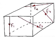
1. Co-planer Forces
2. Non-Co-planer Forces
3. Co-linear Forces
4. Non-Co-linear Forces
5. Concurrent Forces
6. Non-Concurrent Forces
7. Parallel Forces (Like & unlike)
8. Coplanar Concurrent Forces
9. Coplanar Non Concurrent Forces
10. Non-Coplanar Concurrent Forces
11. Non-Coplanar Non Concurrent Forces
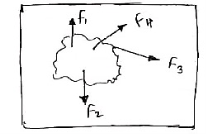
1. Co – planer Force System / Forces:-
The forces whose line of action lies on the same plane are called as Co-planer Forces.
The forces which are acting in the same plane are known as co-planer forces.
2. Non-Co-planer Force System / Forces:-
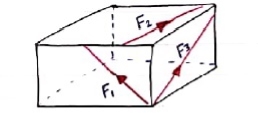
A forces whose line of action does not lie in the same plane ( i.e. lie in different planes )
Forces which are acting in the different planes known as non-co-planer forces (system).
|
3. Co-linear force system / Forces:-
The forces whose line of action lies on the same line are called as co-linear forces.
The forces which are acting along the same straight line are called as co-linear forces.
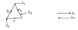
4. Non – Collinear Forces / force system:-
The forces which are not acting along the same straight line are known as non-co-linear forces.
The forces whose line of action doesn’t lie on the same line.
F2
|
5. Concurrent forces / Force system:-
The forces whose line of action meets at one common point are called concurrent forces.
The forces which are passing through a common point are concurrent forces.
The forces which meet at one point are concurrent forces.
6. Non-Concurrent force system / forces:-
The forces which are not passing through common point OR
The forces whose line of action does not meet at common point OR
The force which does not meet at one point is called as non-concurrent forces.
|
7. Parallel Forces / Force system:-
The forces whose lines of actions are parallel to each other are called as parallel forces.
a) Like parallel Forces:-
The forces whose lines of actions are parallel to each other and having same direction are called like parallel forces.
Forces which are parallel to each other & acting in same direction are called as Like parallel forces.
F1 F2 F3
|
b. Unlike parallel Forces:-
The forces which are parallel to each other but having different directions or The forces which are parallel to each other & acting in opposite direction are called as unlike parallel forces.
F1 F2 F3 F4 F5
|
8. Coplanar concurrent forces:-
The forces which meets at one point & their lines of action also lie on the same plane are called as coplanar concurrent force system.
F2 F3
|
9. Coplanar non-concurrent forces:- The forces which do not meet at one point but their line of action lies on the same plane are known as coplanar non-concurrent system of force.
|
10. Non-Coplanar concurrent forces:-The forces which meets at one point but their line of action do not lie on the same plane are known as non-coplanar concurrent forces.
|
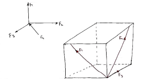
11. Non-coplanar non-concurrent forces:-
|
Their forces which do not meet at one point & their lines of actions do not lie on the same plane are called as non - coplanar non-concurrent forces.
There are four fundamental concepts of classical mechanics. These are
- Space
- Time
- Mass
- Force
All these four principles allow us to study further kinetic units. However, in order to satisfy Newton's second law they should be referred to as base units and the same cannot be taken arbitrarily.
Physical Independence of forces
The physical independence of forces principle states that the effect of a force on a body is never affected by the presence of any other forces. Therefore, even if there are a number of forces acting on the same body, each force has its own influence because the other forces were not present.
Superposition principle states that whenever two or more than two forces act on a particle at the same time, the net force, or resultant force is the vector sum of the two forces.
Superposition principle has many applications in physics, Electrical Engineering, Mechanical Engineering, Quantum mechanics because many physical systems can be easily modelled as linear systems with the help of superposition principle.
The state of the rigid body will not change if force acting on a body is replaced by another force of same magnitude & direction acting anywhere on the body along the line of action of replaced force. The value of force will not change along the Line of action of force within the body.
|
1>. Newton’s 1stLaw:-
Everybody continues to be in its state of rest or in the state of uniform motion along straight line unless it is acted upon by external unbalanced force.
2>. Newton’s 2ndLaw:-
When unbalanced force acts on particle, it will have an acceleration which is proportional to the magnitude of force. This acceleration will be in the direction of force along straight line.
Rate of change of momentum of body is directly proportional to the force acting on it & it is in the direction of force.
3>. Newton’s 3rdLaw:-
Forces of action & reaction between bodies in contact will have same magnitude, line of action but opposite direction.
Resolution and Composition of forces
Composition:-
The process of finding out the resultant force of a given force system.
Resolution:-
It is the procedure of splitting up a single force into number of components without changing the effect of same on the body.
Forces are generally resolved into two components along two mutually perpendicular directions.
Methods of composition / methods for the Resultant force.
A]. Analytical Method B] Graphical Method
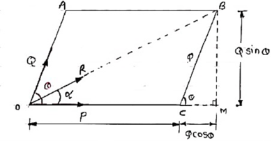
Law of parallelogram of forces:-
If two forces acting simultaneously on a particle, be represented in magnitude & direction by two adjacent sides of parallelogram, then the diagonal passing through the point of intersection of two forces will represent the resultant in magnitude & direction.
|
Consider two forces P & Q acting at a point represented by two sides OA & OC of parallelogram OABC.
Let, θ is the angle between two forces P & Q.
α be the angle between Force P & Resultant R.
Let’s draw a line BM perpendicular to OC which intersects OC at M.
In Δ CMB
Sin θ = BM / BC = BM / Q
BM = Q Sin θ
Also, Cos θ = CM / BC = CM / Q
CM = Q Cos θ
Now in Δ OMB,
We have, (OB) 2 = (OM) 2 + (BM)2
R2 = (OC + CM) 2 + (BM)2
R2 = (P + Q Cos θ) 2 + (Q Sin θ)2
= P2 + 2PQ Cos θ + Q2 Cos2 θ+ Q2 Sin2 θ
= P2 + 2PQ Cos θ + Q2(Cos2 θ+ Q2 Sin2 θ)
= P2 + 2PQ Cos θ + Q2
 Taking sq. root,
R = √P2 + Q2 + 2PQ Cos θ . . . . Magnitude

Tanα = Q Sin θ / P + Q Cos θ . . . . Direction
Examples based on Parallelogram Law of forces:-
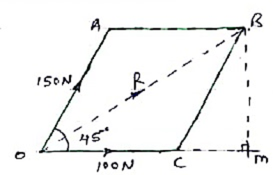
1>. Two forces of 100 N & 150 N are acting simultaneously at a point. What is the resultant of these two forces, if the angle between them is 450.
|
Given: P = 100 N
Q = 150 N
θ = 45o
R = ?α= ?
Solution:
Accr to law of parallelogram of force,
R = √ P2 + Q2 + 2PQ Cos θ
R = √ 1002 + 1502 + 2 x 100 x 150 x Cos 450
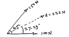
R = 231.76 N
R ≈ 232 N - - - Ans - - - magnitude
tanα = Q Sin θ / P + Q Cos θ
= 150 Sin 450 / 100 + 150 Cos 450
 = 106.066 / 206.066
α = 27.290. . . . . Direction
Ans:
|
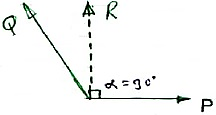
2>. The sum of two forces is 270 N & their resultant is 180 N. If Resultant is Perpendicular to P, find the two forces P & Q.
Given:
P + Q = 270 N
R = 180 N
α = 900
Soln :Accr to law of parallelogram,
Tanα = Q Sin θ / P + Q Cos θ
Tan 90 = Q Sin θ / P + Q Cos θ
∞ = Q Sin θ / P + Q Cos θ
|
Here if P + Q Cos θ = 0, then only above term will become infinity.
Thus, P + Q Cosθ= 0
P = - Q Cos θ
-P = Q Cosθ . . . . (1)
Now, R2 = P2 + Q2 + 2PQ Cos θ
1802 = P2 + Q2 + 2P(-P) . . . from eqn (1)
1802 = P2 + Q2 + (-2P2)
1802 = P2 -2P2 + Q2
1802 = - P2 + Q2
1802 = Q2 - P2
1802 = (Q- P) (Q+ P)
= (Q- P) x 270
Q- P = 1802 / 270
Q- P = 120 . . . (ii)
& we know that
Q + P = 270 . . . (iii)
Solving (ii) & (iii) i.e. add eqn (ii) & (iii)
Q – P = 120
+ Q + P = 270
_______________
2Q + 0 = 390

 2Q = 390
Q = 195 N &P = 75 N . . . Ans
3>. For two forces P & Q acting at a point. Maximum resultant is 2000 N and minimum magnitude of resultant is 800 N. Find values of P & Q.
Sol: We know that,
R2 = P2 + Q2 + 2PQ Cos θ
For max value of R, Cos θ must be 1 i.e. Cos θ = 1
i.e. θ = 0, then only cosθ = 1
Rmax = √ P2 + Q2 + 2PQ Cos θ
= √ P2 + Q2 + 2PQ Cos 0
= √ P2 + Q2 + 2PQ
2000 = √ P2 + 2PQ + Q2
 = √ (P + Q)2
2000 = P + Q . . . .Eqn (1)
Now for minimum value of R,
θ = 1800
Rmin= √ P2 + Q2 + 2PQ Cos θ
= √ P2 + Q2 + 2PQ Cos θ
= √ P2 + Q2 - 2PQ
= √ P2 - 2PQ+ Q2
= √ (P – Q)2
800 = P – Q . . . . . eqn (ii)
Solving eqn (i) &eqn (ii) we get,
i.e. Add eqn (i) & (ii),
P + Q = 2000
P - Q = 800
_______________
2P + 0 = 2800
P = 2800 / 2
P = 1400 N ….Ans
&P + Q = 2000
1400 + Q = 2000
Q = 600 N . . . Ans
Ans P = 1400 N
Q = 600 N
4>. The angle betn the two forces P & Q is θ. If Q is doubled then new resultant is perpendicular to P. Prove that Q = R.
|
R2 = P2 + Q2 + 2PQ Cos θ . . . (1)
Also tan 90 = Q Sin θ / P + Q Cos θ
∞ = 2Q Sin θ / P + (2Q) Cos θ= Q
If P + (2Q) Cos θ = 0 then only above term will be infinity.
P + (2Q) Cos θ = 0
-P = (2Q) Cos θ-- put in eqn (I)
R2 = P2 + Q2 + (P x (-P))
= P2 + Q2 - P2
R2 = P2
Taking sq. root
R = P -- -Proved
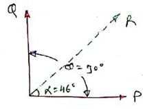
5>. The angle betn the two concurrent forces is 900 & their resultant is 2500 N. The resultant makes an angle of 460 with one force. Determine magnitude of each force. PU – many 14 – 4m
|
By using, R2 = P2 + Q2 + 2PQ Cos θ
25002 = P2 + Q2 + 2PQ Cos 90
As cos 90 = 0 then
25002 = P2 + Q2 . . . (1)
Now,
Tanα = Q Sin θ / P + Q Cos θ = Q Sin 90 / P + Q Cos 90
Tanα = Q / P
Tan46 = Q / P
Q = 1.0355 P - - substitute in eqn (1)
25002 = P2 + [(1.0355)2 P2]
P2 = 3017537.93


P = 1737 N Q = 1798 N
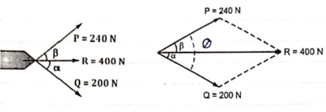
Resultant force R = 400 N has two component forces P = 240 N and Q = 200 N as shown. Determine direction of component forces i.e. α and β w.r.t. resultant force.
Let Q = (α + β )
Using law of parallelogram,
|
R2 = P2 + Q2 + 2PQ Cos θ
4002 = 2400 + 2002 + 2 x 240 x 200 Cos θ
62400 = 96000 Cos θ
Cos θ = 62400 / 96000 = 0.65
θ = Cos-1 (0.65) = 49.460
θ = 49.460
We know that
Tanβ = Q Sin θ / P + Q Cos θ
Tanβ = 200 Sin θ / 240 + (200 Cos θ)
= 200 Sin 49.46 / 240 + (200 Cos 49.46)
= 0.411
 β = tan-1 (0.411)
β = 22.330 -- Direction of P
Q = α + β
 49.46 = α + 22.33
α = 27.130 -- Direction of Q
Polygon law of vector addition states that if a number of vectors are represented by the sides of a polygon in magnitude and direction taken in the same order, then their resultant is also represented in magnitude and direction by the closing side of the polygon taken in the opposite order.
Procedure:
Consider a number of vectors that are supposed to be added
Draw the first vector with a suitable scale in a given direction.
Now from the head of first vector, draw the second vector with the same scale and in the same direction of second vector.
Join the vector, the vector joining the tail of first and the head of last vector represents the resultant completely.(direction & magnitude both).
Resultant of Concurrent coplanar force systems
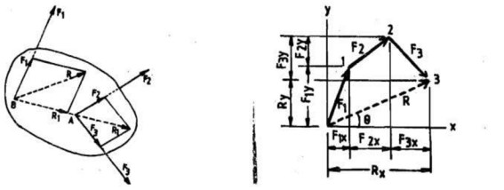
The technique for resolution of a force can be used to determine the resultant of coplanar concurrent forces. If ‘n’ concurrent forces F1,F2,F3, .. . . .Fn are acting at a point in a body then each force can be resolved into two mutually perpendicular directions. Therefore, we get ‘2n’ components. Nevertheless, each set of 2n components acts in one direction only. Hence, all these components can be algebraically added to get the resultant component.
Coplanar Non Concurrent Force System
The resultant force is obtained by adding two forces at a time and then combining their sums. The three forces Fl, F2 and F3 shown in figure can be combined by first adding any two forces like F2 and F3. They may be moved along their lines of action to their point of concurrency ‘A’ by the principle of transmissibility.
|
The law of parallelogram of forces forms their sum R1.
The force R1 may then be combined with F1 by the parallelogram law at their point of concurrency B in order to obtain the resultant R of the three given forces.
Here, the order of combination of the forces is immaterial as may be verified by combining them in a different sequence.
Now, the force R can be applied at any point on its established line of action.
Moment:-
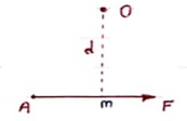
The turning effect produced by a force on the body on which it acts is called as Moment.
Moment of force about any point is the product of magnitude of force and perpendicular distance of force from the point about which moment is to be taken.
|
Let force F is applied at point A as shown & O is any point about which we want to take moment.
Thus from point O, draw OM line perpendicular to the line of action of force.
OM = d = Perpendicular distance betn Force & point O.
Moment = M = F xd
Graphical representation of Moment:-
Select suitable scale to locate the force graphically.
Draw a line parallel to line of action of force. Length of this line can be calculated from selected scale.
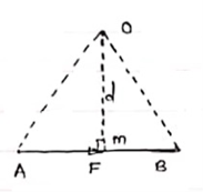
Length of a line will be equal to magnitude of force.In the figure, Force F is represented by line AB.
Now let O is the moment centre &
OM = d = perpendicular distance
By definition, Mo = F xd
|
Now join OA & OB, then
In Δ OAB
Area (ΔOAB) = ½ x AB x OM
2 (Area of ΔOAB) = F xd = Mo
Thus the moment of any force about any point is numerically equal to twice area of triangle in which base represents force & height represents the perpendicular distance.
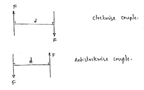
A pair of two equal and opposite (unlike) parallel forces (of same magnitude) is known as couple.
Properties of Couple:-
1>. Two unlike parallel, non-collinear forces of same magnitude will form couple.
2>. Resultant of couple is always zero.
3>. Moment of couple is product of one of the force & lever arm of couple.
M = F xd
Lever arm of couple = ḻlar distance betn couple forces.
4>. Couple cannot be balanced by single force.
5>. Couple can be balanced only by another couple of opposite nature.
6>. Moment of couple is independent of moment centre. i.e. Ref. point is not required to take moment of couple.
|
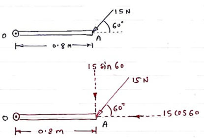
A force of 15 N is applied at an angle of 600 to the edge of door as shown in figure. Find the moment of this force.
|
Solution:-
Resolving force at point B & then taking the moment about point O,
M0 = (15 Cos 60 x 0) + (15 Sin 60 x 0.8)
 = 0 + 10.39
M0 = 10.39 N.m
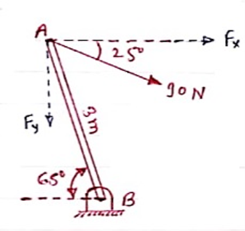
A 90 N force is applied to the control rod AB. Determine moment of this Force about point B.
Solution:-
As we don’t know perpendicular distance betn force & point ‘ B ’, Let us resolve the force into two components.
X – Component of force
Fx = 90 Cos 25 = 81.567 N
Y – Component of force
Fy = 90 Sin 25 = 38.036
Now taking moments about point B.
MB = [Fx x (3 Sin 65)] - [Fy x (3 Cos 65)]
MB = (81.65 x 2.72) – (38.036 x 1.27)
 = 221.843 – 48.31
MB = 173.53 N.m
|
Examples on Non concurrent forces & use of Varigon’s theorem
1>. Determine the resultant of the system of forces acting on a beam as shown in figure.
|
Above Force system is Non concurrent force system.
Resolving the forces horizontally,
∑ Fx = - 20 Cos 60 = - 10 KN = 10 KN (towardleft)
Resolving forces vertically,
∑Fy = - 20 – 30 – 20 Sin 60
= - 67.32 KN
∑Fy = 67.32 KN (downwards)
Resultant,R = √ (∑ Fx) 2 + (∑Fy) 2 = √10 2 + 67.322
R = 68.06 KN
Direction of Resultant,
 tanα = ∑Fy / ∑ Fx = 67.32 / 10.00
α = 81.550
Now taking moment about point A & using Varignon’s theorem.
∑MA = Moment of resultant A
(20 x 1.5) + (30 x 3) + (20 Sin 60 x 6) = (∑ Fx x 0 ) + (∑Fyx X)
223.92 = 67.32 x X
X = 223.92 / 67.32 = 3.326 m from point A
Ans
|
For a given force system, find the resultant in magnitude & direction. Also find the location of Resultant.
|
Solution
|
Resolving forces horizontally,
∑ Fx = - 15 + 25 Cos 40 = 4.15 N (toward right)
Resolving forces vertically,
∑Fy = 25 Sin 40 – 10
= 6.07 n (upward)
R = √(∑ Fx) 2 + (∑Fy)2
 = √4.152 + 6.072
R = 7.35 N
 tanα = ∑Fy / ∑ Fx = 6.07 / 4.15
α= 55.640 - - - Angle made by resultant
To find exact position of R, let x is the perpendicular distance betn R & point B.
Using Varignon’s theorem at point B.
R x X = ∑MB
= (10 x 150) – (15 x 150 Sin 50) + ( 25 x 375 ) – ( 6.25 x 1000 )
= 1500 – 1723.6 + 9375 – 6250
= 2901.4 N.mm (clockwise)
x = 2901.4 / R
 = 2901.4 / 7.35
x = 394.75 mm from point B.
|
(Q) Find resultant moment of two couples for the loading as shown in Fig
|
Moment of 50 N couple is clockwise,
= 50 x 1
= 50 N.m
Moment of 100 N couple is also clockwise
= 100 x 0.8 = 80 N.m.
Resultant Moment = 50 + 80 = 130 N.m
(Q) Find the resultant and its point of application on y – axis for the force system acting on Triangular plate as shown in fig.
|
θ = tan-1 (3/4)
= 36.860 with Horizontal
Resolving forces in x & y dirn
∑ Fx = 20 – 50 Cosθ
= 20 – 50 Cos 36.86
= - 20 N
= 20 N
∑Fy = - 30 + 50 Sin 36.86
= 0.00007
≈ 0
R = √(∑ Fx) 2 + (∑Fy)2 = 20 N toward left (as ∑ Fy = 0 )
Let us apply Varignons theorem at point B
∑MB = R.x
( 30 x 4 ) = Rx
Rx = -120 N.m = 120 N.m
As moment of Resultant is negative i.e. it is anticlockwise
-Rx = -120
X = -120 / -20 = 6 m
X = 6 m from point B and it will be above point. B to create anticlockwise moment.
(Q) If the resultant moment about point A is 4800 Nm clockwise, determine the magnitude of F3 if F1 = 300 N and F2 = 400 N.
|
Given: Resultant Moment = 4800 N.m
Let us apply Varignon’s theorem at point A,
∑MB = (R.x )
|
[(300 60) x 2] + [(400 Sin 60) x 5] + [(F3 Sin 53.13 x 5)] – [(F3 Cos 53.13) x 4] = 4800
519.62 + 1732.05 + 3.99 F3 – 2.4 F3 = 4800
2251.67 + 1.59F3 = 4800
1.59 F3 = 2548.33
F3 = 2548.33 / 1.59 F3 = 2548.33 / 1.6
OR

 F3 = 1602.72 N F3 = 1592.7 N
(Q) The three forces shown in Fig. create a vertical resultant acting through point B. If P = 361 N, compare the values of T and F.
|
From given figure,
1>. Angle made by Force P is, = tan-1 (3/3) = 450 with Horizontal
2>. Angle made by Force F is, = tan-1 (1/3) = 18.430 with Horizontal
3>. Angle made by Force T is, = tan-1 (3/1) = 71.560 with Horizontal
|
Resolving forces along x & y dirn,
As Resultant is vertical, let it is upward, then
∑ Fx = 0& ∑Fy = R
∑ Fx = P Cos 45 + F Cos 18.43 – T Cos 71.56
0 = 361 Cos 45 + F Cos 18.43 – T Cos 71.56
0 = 255.26 + 0.95 F – 0.32 T
0.95 F – 0.32 T = - 255.26 . . . . (1)
∑Fy = P Sin 45 – F Sin 18.43 + T Sin 71.56
R = 361 Sin 45 – F Sin 18.43 + T Sin 71.56
R = 255.26 – 0.32 F + 0.95 T …… (2)
Now as it is given that Resultant acts at point B, let us apply Varignon’s theorem at point B.
∑MB = R.x
But as R is acting at B point, its perpendicular distance from point B itself will be zero.
∑MB = R.x
(P Cos 45 x 1) – (P Sin 45 x 2) + (T Cos 71.56 x 1) – (T Sin 71.56 x 1) – (F Cos 18.43 x 1) + (F Sin 18.43 x 2) = R x 0
As P = 361 N
-255.26 – (255.26 x 2) + 0.32 T – 0.95 T – 0.95 F + (0.32 F x 2) = 0
-765.78 + 0.32 T – 0.95 T – 0.95 F + 0.64 F = 0
-765.78 – 0.63 T – 0.31 F = 0
– 0.31 F – 0.63 T = 765.78 . . . . (3)
Solving eqn (1) and (3) simultaneously

 0.95 F – 0.32 T = - 255.26
-0.31 F – 0.63 T = 765.78

F = -581.716 N &

T = -929.282 N
(Q) Determine the resultant of four forces tangent to the circle of radius 1.5 m as shown. Determine its location w.r.t. ‘O’.
|
Resolving forces in X and Y direction,
∑ Fx = 24 - 16 Cos 45
= 12.69 KN ( )
∑Fy = -12 + 8 – 16 Sin 45
= -15.31 kN
= 15.31 kN ( )
Resultant R = √(∑ Fx) 2 + (∑Fy)2
 = √ 12.69 2 + (-15.31)2
R = 19.88 kN
Direction of Resultant,
α = tan-1(∑Fy / ∑ Fx)
 α = tan-1(15.31 / 12.69)
α = 50.350in 4th quadrant
To know exact location of Resultant, let us apply Varignon’s theorem at point O.
∑MO = R.x
-(12 x 1.5) + (24 x 1.5) – (8 x 1.5) + (16 x 1.5) = (19.88 x X)
30 = R.x
As product of R.x is positive it means moment of Resultant is positive. To create positive clockwise moment of Resultant it must be acting on Right side of O (in 4th quadrant).
30 = 19.88 x X
X = 1.51 m from O on the right hand side.
|
It states that if number of forces are acting simultaneously on a body, the algebraic sum of moments of all the forces about any point is equal to moment of their resultant about same point.
Mathematically,
∑(F xd) = (R x X)
Where, F = All forces acting on a body
d = ḻlar distance
R = Resultant of all forces
X = ḻlar distance of Resultant force about a point where moment is taken.
Use:- This theorem is useful to calculate or find the position or location of Resultant of non-concurrent force system.
References:-
R. C. Hibbler, Engineering Mechanics: Principles of Statics and Dynamics, Pearson Press
Bansal R. K., A Text Book of Engineering Mechanics, Laxmi Publications.
