Module 2
Boilers
A boiler is an enclosed vessel that provides a means for combustion and transfers heat to water until it becomes hot water or steam. The hot water or steam under pressure is then usable for transferring the heat to a process.
A boiler is an enclosed vessel that provides a means for combustion and transfers heat to water until it becomes hot water or steam. The hot water or steam under pressure is then usable for transferring the heat to a process.
Depending upon the relative position of Water and Flue gases:
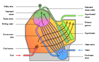
- Water Tube Boiler: A high-pressure water tube boiler is a type of boiler in which water circulates in tubes heated externally by the fire. Fuel is burned inside the furnace, creating hot gas that boils water in the steam-generating tubes. In smaller boilers, additional generating tubes are separate in the furnace, while larger utility boilers rely on the water-filled tubes that make up the walls of the furnace to generate steam.

Fig. 1: Water tube boiler
Examples: Babcock Wilcox boiler.
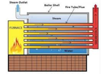
2. Fire Tube Boiler: A fire-tube boiler is a type of boiler in which hot gases pass from a fire through one or (many) more tubes running through a sealed container of water. The heat of the gases is transferred through the walls of the tubes by thermal conduction, heating the water and ultimately creating steam.

Fig.2: Fire tube boiler
Examples: Cochran Boiler, Lancashire Boiler, etc.
Lancashire Boiler is a horizontal type and stationary fire tube boiler. This boiler was invented in the year 1844, by William Fairbairn. This is an internally fired boiler because the furnace uses to present inside the boiler. This boiler generates low-pressure steam and it is a natural circulation boiler. It has a high thermal efficiency of about 80 to 90 percent. The size is approximately 7-9 meters in length and 2-3 meters in diameter.
Parts of Lancashire boiler:
- Safety valve
- Pressure Gauge
- Feed check valve
- Water Level Indicator
- Blow off valve
- Steam stop valve
- Manhole
- Fire door
- Fusible Plug
- Ash pit
- Economizer
- Air preheater
- Superheater
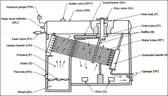
- This is one of the important types of a water tube boiler used in the powerhouses for power generation as shown in Fig. It consists of some inclined water tubes (WT) connected between the uptake header (UH) and the down take header (DH).
- The whole combustion chamber is divided into some parts with the help of baffles (B). Hot gases first move from the furnace (F) upwards between the water tubes and then move downward and upwards between the baffles over the tubes and finally, these are exhausted to the chimney through the damper (DP).
- The feedwater enters the front of the drum (DR) and travels to the back part of the drum and then descends through the vertical tube to the down take header.
- From here the water enters into the water tubes to the uptake header and then again to the drum. The water tubes near the uptake header are in contact with the hotter flue gases compared to the portion near the down take header due to which the water in the uptake header rises due to decreased density and enters the drum which is replaced by the colder water from the down take header.
- Water continues to circulate like this till it is evaporated. This type of circulation of water occurring due to density difference is called free circulation. The superheating of steam is done in the superheater (SH). It consists of a large number of steel tubes.
- Wet steam from the boiler drum enters the outer tube (OT), then passes into the superheated tubes, and during its passage, it gets further heated up. Superheated steam now enters into the inner tubes (IT) and from here it is withdrawn through a stop valve (SV).
- The boiler also has its usual mountings like pressure gauge (PG), safety valve (SFV), water level indicators (WLI), feed valve (FV), etc.

Fig.3: Babcock and Wilcox Boiler
Boiler Mountings: This can be defined as the important components which are generally mounted on the surface of the boiler while operation for its efficient working.
Seven required mountings can be an essential part of the boiler while operating:
- Safety valve
- Feed check valve
- Water level indicator
- Blow off cock
- Mainstream stop valve
- Fusible plug
- Pressure gauge
Boiler Accessories: These are the auxiliary plants or components required for steam boilers for their proper operation and to increase the efficiency of the boilers.
There are seven boiler accessories are also present for supporting the operation of the boiler. They are:
- Steam trap
- Feed pump
- Steam separator
- Injector
- Superheater
- Economizer
- Air preheater
A turbine is a turbomachine with at least one moving part called a rotor assembly, which is a shaft or drum with blades attached. Moving fluid acts on the blades so that they move and impart rotational energy to the rotor.
There are two major categories of hydraulic turbine:
- Impulse Turbine:
The steam jets are directed at the turbine's bucket-shaped rotor blades where the pressure exerted by the jets causes the rotor to rotate and the velocity of the steam to reduce as it imparts its kinetic energy to the blades.
The blades in turn change the direction of flow of the steam however its pressure remains constant as it passes through the rotor blades since the cross-section of the chamber between the blades is constant.
Impulse turbines are therefore also known as constant pressure turbines. The next series of fixed blades reverses the direction of the steam before it passes to the second row of moving blades.
2. Reaction turbine:
A reaction turbine is a type of turbine that develops torque by reacting to the pressure or weight of a fluid; the operation of reaction turbines is described by Newton's third law of motion (action and reaction are equal and opposite).
The rotor blades of the reaction turbine are shaped more like aerofoils, arranged such that the cross-section of the chambers formed between the fixed blades diminishes from the inlet side towards the exhaust side of the blades.
Impulse turbine works on the basic principle of impulse. When the jet of water strikes at the turbine blade full of its speed, it generates a large force which is used to rotate the turbine.
The force depends on the time interval and velocity of the jet strikes the blades.
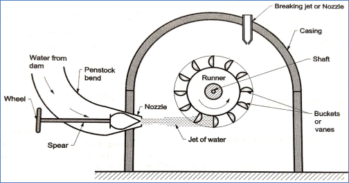
This turbine is used to rotate the generator, which produces electric power. High-pressure water flows from the dam (high head) to the nozzle (low head).

Fig.4: Pelton wheel turbine
- This water flows through a divergent nozzle where it’s all its pressure energy changes into kinetic energy. It forms a water jet.
- The water jet strikes the blade at high speed which rotates the rotor. It transfers all kinetic energy of water to the rotor, which further use to rotate the generator.
- After transferring energy, water flows to the tailrace. This process runs continuously until sufficient power generates.
Francis Turbine is a mixed combo of both impulses as well as reaction turbine, where the blades of the turbine rotate by using both reaction and impulse force of water flowing through them producing electricity more efficiently. Francis turbine is used for the production of electricity in hydropower stations.
The main reason for the higher efficiency of the Francis turbine lies in the design of blades; these blades rotate using both reaction and impulse force of water flowing through them. Due to the use of this type of turbine the main problem faced due to the water head availability is eliminated as the turbine uses both the kinetic and potential energy to produce power.
The Kaplan turbine is a propeller-type water turbine that has adjustable blades. It was developed by combining the automatically adjusted propeller blades with automatically adjusted wicket gates to achieve efficiency over a wide range of flow and water level. Kaplan turbines are nowadays used for high-flow, low-head power production.
Hydraulic pumps are the mechanical devices which are used in hydraulic drive system which can be either a hydrostatic or a hydrodynamic system. It is the mechanical equipment that is responsible for the conversion of mechanical power into hydraulic power. It tends to generate flow with an optimum power to overcome pressure induced by the load at the pump outlet.
There are two major classifications of hydraulic pump, there are mentioned below:
- Reciprocating pump: These pumps are positive displacement pumps that are initially a small quantity of liquid is taken into the chamber and is physically displaced and forced out with pressure by moving mechanical elements.
The use of reciprocating pumps is being limited these days and being replaced by centrifugal pumps.
For industrial purposes, they have become obsolete due to their high initial establishment and maintenance.
2. Centrifugal Pump: It is one of the classifications of hydraulic pump which converts hydraulic energy into mechanical energy by a centrifugal force. It works on the principle of forced vortex flow which means when a certain mass of fluid is rotated by external torque rise in pressure head takes place. Components of centrifugal pumps are:
- Impeller,
- Casing,
- Suction pipe,
- Foot valve and strainer,
- Delivery pipe.
Common applications are sewage, petrochemical pumping, etc.
1. Cavitation:
It is the formation and then immediate implosion of cavities in a liquid that are consequences of forces acting upon the liquid.
Major places where cavitation occurs are in pumps, on propellers, or at restrictions in a flowing liquid. Cavitation is a significant cause of wear in some engineering contexts.
2. Priming:
Priming of a pump is a very essential step in the start-up of a centrifugal pump. The fact is that centrifugal pumps are not capable of pumping air or vapours.
Priming is the process in which the impeller of a centrifugal pump will get fully submerged in liquid without any air trap inside. This is especially required when there is the first startup. The priming of positive displacement is required only at the time of first starting. In this case, priming means filling liquid in the casing and aim to diminish the clearance volume.
It can be removed from the air by its pumping action, this is called self-priming.
References:
- J K Gupta and R S khurmi
- Various presentations from google.
- Notes developed by Shubham Tyagi
- Notes provided by the firm.