Module 3
Combustion Engine
An I.C Engine is a heat engine in which combustion of a fuel occurs with an oxidizer in a combustion chamber that is an integral part of the working fluid flow circuit.
There are two kinds of internal combustion engines currently in production that is the spark-ignition gasoline engine and the compression ignition diesel. Most of these are four- strokes cycle engines, meaning four piston strokes are needed to complete a cycle.
There are various components or parts of IC Engine, which are mentioned below:
- Crankshaft
- Exhaust camshaft
- Inlet camshaft
- Piston
- Connecting rod
- Spark Plug
- Valves
- Cooling water jacket
Two-stroke engines are a type of internal combustion engine which completes a power cycle with two strokes (up and down movements) of the piston during only one crankshaft revolution.
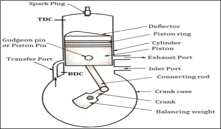
Fig. 1: Two stoke Petrol engine
Piston: It is used to compress the charge (air-fuel mixture) during the compression stroke and to transmit the force to the connecting rod and then crank during the power stroke. The piston of the two-stroke engine is given a specific crown shape (deflector) which guides the charge in the upward direction.
Inlet and exhaust Port: Inlet Port controls the admission of the charge into the crankcase and the exhaust port is used for the removal of exhaust gases after doing work on the piston.
Transfer Port: The charge present in the crankcase is transferred into the cylinder of the engine by using the transfer port.
In two strokes engine valves are therefore eliminated and ports are used for suction and exhaust purpose.
Working of Two strokes SI Engines
- Consider that, initially the piston is at BDC. The arrangement of the ports is such that the piston performs two operations simultaneously.
- When the piston starts rising from BDC, it Closes the transfer port and exhaust port, and the already existing charge in the cylinder is compressed.
- At that time, due to the upward motion of the piston, a vacuum is created in the crankcase. As soon as the inlet port is uncovered the fresh charge (air + fuel) is sucked into the crankcase and the charging is continued until the crankcase is filled.
- At the end of this first stroke, the piston reaches TDC. Just Before the completion of this compression stroke, the compressed charge is ignited using a spark plug.
SECOND STROKE:
- In this stroke, the piston moves from TDC to BDC. Due to combustion of charge, very high pressure and temperature gases are created.
- These high-pressure gases exert a large amount of force on the crown of the piston and thus piston is pushed down which produces some useful work.
- The downward movement of the piston closes the inlet port and compresses the charge already sucked in the crankcase. This fresh charge is transferred on the top side of the piston through the transfer port.
- At that time, the exhaust port opens and burnt gases are escaped.
Four-stroke engines are a type of internal combustion engine that completes a power cycle with four strokes (up & down movements) of the piston during two crankshaft revolutions.
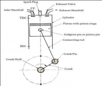 Fig. 2: Four Stroke S.I. Engine
Working of four strokes S.I Engine:
The suction stroke starts with the piston at the top dead center position (TDC). During this stroke, the piston moves downwards through the crankshaft.
The inlet valve is opened, and the exhaust valve remains closed. The partial vacuum is created by the downward movement of the piston. Due to this, the fresh charge (a mixture of air and petrol) from the carburetor is taken into the cylinder through the inlet valve.
The stroke is completed during the half revolution (180°) of the crankshaft, which means at the end of the suction stroke, the piston reaches the bottom head center position.
COMPRESSION STROKE:
During this stroke, the inlet and exhaust valves remain closed and the piston returns from the bottom dead center position (BDC) to TDC.
As the piston moves up, the charge is compressed up to clearance volume. During compression, the pressure and temperature rise.
Just before the completion of the compression stroke, the charge is ignited through an electric spark, produced at the spark plug. Due to the instantaneous burning of charge, pressure, and temperature of charge tremendously rises.
WORKING OR EXPANSION STROKE OR POWER STROKE:
During this stroke, the inlet and exhaust valves remain closed. The expansion of gases due to the heat of combustion exerts pressure on the piston due to which the piston moves downward, doing some useful work.
The high pressure and temperature of gases push the piston in a downward direction. The piston moves from TDC to BDC.
EXHAUST STROKE:
During this stroke, the inlet valve remains closed and the exhaust valve is opened. The piston moves upward (from BDC to TDC position) with the help of energy stored in the flywheel during the working stroke.
During upward movement, the piston pushes out burnt gases through the exhaust valve. At the end of the exhaust stroke, the piston reaches to TDC position, the exhaust valve is closed and the inlet valve is opened which starts the next cycle.
C.I. Stands for Compression ignition. Generally, all Diesel engines are Compression Ignition engines (C. I.)
The construction of four strokes S.I. (Petrol) & four-stroke C. I. (Diesel) engine is much similar. The only difference is that SPARK PLUG of S.I. Engine is replaced by Fuel Injector (F.I.) in C.I. Engines.
Unlike S.I. Engines, In C.I. Or diesel Engines only air is taken into the cylinder during the suction or inlet stroke, and diesel fuel is injected into compressed air at the end of the compression stroke.
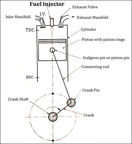
Fig. 3: Four strokes diesel engine
SUCTION STROKE OR INTAKE STROKE:
The suction stroke starts with the piston at the top dead center position (TDC). During this stroke, the piston moves downwards through the crankshaft.
The inlet valve is opened, and the exhaust valve remains closed. The partial vacuum is created by the downward movement of the piston. Due to this, the fresh air is taken into the cylinder through the inlet valve.
The stroke is completed during the half revolution (180°) of the crankshaft, which means at the end of the suction stroke, the piston reaches the bottom head center position.
COMPRESSION STROKE:
During this stroke, the inlet and exhaust valves remain closed and the piston returns from the bottom dead center position (BDC) to TDC.
As the piston moves up, the AIR is compressed up to clearance volume. During compression the pressure and temperature of air rise.
Just before the completion of the compression stroke, the Diesel Fuel is injected into this compressed air by using a fuel injector. Due to very high pressure and temperature of the air, Diesel fuel starts burning instantaneously producing very pressure and temperature of gases.
WORKING OR EXPANSION STROKE OR POWER STROKE:
During this stroke, the inlet and exhaust valves remain closed. The expansion of gases due to the heat of combustion exerts pressure on the piston due to which the piston moves downward, doing some useful work.
The high pressure and temperature of gases push the piston in a downward direction. The piston moves from TDC to BDC.
EXHAUST STROKE:
During this stroke, the inlet valve remains closed and the exhaust valve is opened. The piston moves upward (from BDC to TDC position) with the help of energy stored in the flywheel during the working stroke.
During upward movement, the piston pushes out burnt gases through the exhaust valve. At the end of the exhaust stroke, the piston reaches to TDC position, the exhaust valve is closed and the inlet valve is opened which starts the next cycle.
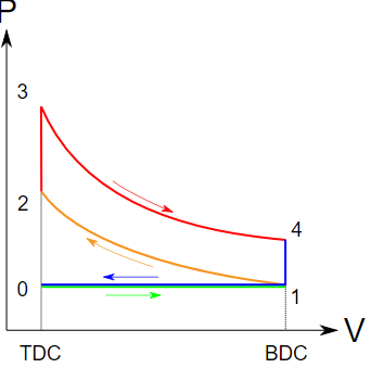
Fig.4: PV diagram of the otto cycle
The Otto cycle is a description of what happens to a mass of gas as it is subjected to changes of pressure, temperature, volume, the addition of heat, and the removal of heat. The mass of gas that is subjected to those changes is called the system. The system, in this case, is defined to be the fluid (gas) within the cylinder. By describing the changes that take place within the system, it will also describe in the inverse, the system's effect on the environment. In the case of the Otto cycle, the effect will be to produce enough network from the system to propel an automobile and its occupants in the environment.
The Otto cycle is constructed from:
- Top and bottom of the loop: a pair of quasi-parallel and isentropic processes (frictionless, adiabatic reversible).
- Left and right sides of the loop: a pair of parallel isochoric processes (constant volume).
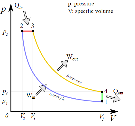
Fig.5: PV Diagram for diesel engine
The Diesel cycle is a combustion process of a reciprocating internal combustion engine. The Diesel cycle is assumed to have constant pressure during the initial part of the combustion phase (V2 to V3 in the diagram, below).
1→2: isentropic compression of the fluid (blue)
2→3: reversible constant pressure heating (red)
3→4: isentropic expansion (yellow)
4→1: reversible constant volume cooling (green)
Question1: Following observations were recorded during a test on a single cylinder 4- stroke oil engine
Bore =300mm; Stroke = 450mm; Speed =300rpm; imep = 6bar; Net brake load = 1.5 kN; Brake drum diameter = 1.8m; Brake rope diameter = 2 cm.
Calculate: (i) Indicated Power
(ii) Brake Power
(iii) Mechanical Efficiency
Solution

 (Ans)
(Ans)
 (Ans)
(Ans)

Question 2: A four-cylinder two-stroke cycle petrol engine develops 30 KW at 2500rpm. The mean effective pressure on each piston is 8 bars and mechanical efficiency is 80%. Calculate the diameter and stroke of each cylinder with a stroke bore ratio of 1.5. Also calculate the fuel consumption of the engine, if brake thermal efficiency is 28%. The calorific value of the fuel is 43900 kJ/ kg.
Sol: 

Also
Or

Or D = .062 m or 62 mm (Ans)

(ii) Fuel Consumption:


Question 3: A 4- cylinder, 4-stroke petrol engine having 90 mm bore and 130mm stroke develops 30 kW of power while running at 1500 r.p.m and using a 20% rich mixture. The theoretical air-fuel ratio is 15:1. The calorific value of petrol is 46000 kJ/ kg. Volumetric efficiency measured at 15oC and 760 mm of mercury as standard temperature and pressure is 70% and mechanical efficiency is 90%.
Find:
(i) Indicated Thermal efficiency
(ii) Brake mean effective pressure
(iii) Brake Thermal efficiency
Sol:
Total swept volume of the engine


 Volume of air drawn in the engine in the suction stroke


The volume flow rate of the 4-stroke engine


= 1.737 m3/min
This volume flow rate is at pressure 760 mm of mercury (1.013 bar) and temperature 15o C (298K).
So the mass flow rate of air

= 2.057 kg/min
The mass flow rate of fuel used = 

Using 20% rich mixture actual mass flow rate of fuel used

= 0.164 kg/min

Given that, Brake power, B.P = 30 kW


(a) Indicated Thermal Efficiency

= 0.264 or 26.4% (Ans)
(b) Brake thermal efficiency
 (Ans)
(Ans)
(c) Brake mean Effective Pressure


The refrigerator is a device (which operates in a cycle) that removes the heat from a low-temperature Body (heat sink) & rejects it to a body at high temperature (heat source) at the expense of external work supplied to it.
A refrigerator's main purpose is to maintain a low temperature in an enclosed space, so it absorbs the heat from the enclosed space and rejects it to the surrounding environment. Thus here, the desired effect or the output of the refrigerator is the cooling effect produced by it.
The refrigerating effect is the amount of heat absorbed by the refrigerant during its travel through its evaporator.
The refrigerating effect is the rate of heat absorption from the substance and space to be cooled.
One ton of refrigeration is defined as the refrigerating effect produced by melting of one ton of ice from and at zero degrees Celsius in twenty-four hours.
Amount of heat required to remove to form one ton of ice in 24 hours from water at zero degree Celsius.
Ice making capacity is the amount of ice produced per unit of time. A much less common definition is: 1 tonne of refrigeration is the rate of heat removal required to freeze a metric ton (1000 kg) of water at 0°C in 24 hours.
The efficiency of a Refrigerator is expressed in terms of the Coefficient Of Performance (C.O.P.)
Coefficient of Performance (C.O.P.) is the measure of performance of the Refrigerator.
Coefficient of Performance (C.O.P.) of Refrigerator is the ratio of desired work output or desired cooling effect or Refrigeration Effect produced by Refrigerator to the Energy input given to Refrigerator.
Coefficient of Performance (C.O.P.) in general can be expressed as:
(COP)R= Desired Cooling Effect or Desired Work output or Refrigeration Effect
Energy input or work input
=Q2/W
Relative COP:
The relative coefficient of performance is defined as the ratio of the actual coefficient of performance to the theoretical coefficient of performance.
Relative C.O.P. = Actual C.O.P./Theoretical C.O.P.
A refrigerant is a substance or mixture, usually, a fluid, used in a heat pump and refrigeration cycle. In most cycles, it undergoes phase transitions from a liquid to a gas and back again. Many working fluids have been used for such purposes. Fluorocarbons, especially chlorofluorocarbons, became commonplace in the 20th century, but they are being phased out because of their ozone depletion effects.
Other common refrigerants used in various applications are ammonia, sulphur dioxide, and non-halogenated hydrocarbons such as propane.
The working fluid or often called refrigerant would have favourable thermodynamic properties which are mentioned below:
- To be noncorrosive to mechanical components,
- To be safe, including freedom from toxicity
- To be free from flammability.
- It would not cause ozone depletion or climate change.
Vapour- compression refrigeration system, in which the refrigerant undergoes phase transformation which is among many of the refrigeration cycles and is the most widely utilized technique for cooling or air-conditioning of buildings along with automobiles. It is used in domestic as well as commercial refrigerators, on large-scale warehouses for chilled or frozen storage of foods and eatables like meats, refrigerated trucks and railroad cars, and a host of other commercial and industrial services. Oil refineries, petrochemical and chemical processing plants, and natural gas processing plants are among the many types of industrial plants that often utilize large vapour-compression refrigeration systems.
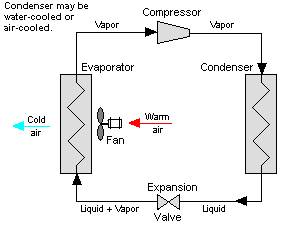
Fig.6: Vapour compression cycle
Vapour Absorption Refrigeration System:
The vapour absorption refrigeration system is one of the oldest methods of producing a refrigerating effect. In this system ammonia is used as the refrigerant and water is used as the absorbent.
The vapour absorption system uses heat energy instead of mechanical energy as in vapour compression system, to change the conditions of the refrigerant for the operation of the cycle.
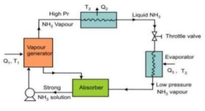
Fig.7: Diagram of vapour absorption refrigeration system
A domestic refrigerator is essentially small cold storage where several food products such as ice cream, meat, fish, milk, fruits, vegetables, water, etc. can be stored at reduced temperatures. The most common domestic refrigerator uses a vapour compression refrigeration system for maintaining required storage conditions, even though a small number of refrigerators use the principle of triple fluid vapour absorption refrigeration system. Domestic refrigerators are available in a wide range of sizes and designs. The domestic refrigerator is normally specified by the storage volume (gross or net), e.g. a 300-liter refrigerator means a domestic refrigerator with an internal storage volume of 300 liters.
Application of refrigerator:
- Food processing, prevention, and distribution
- Beverage
- Candy
- Medical
Principle:
An air conditioner collects hot air from a given space, processes it within itself with the help of a refrigerant and a bunch of coils, and then releases cool air into the same space where the hot air had originally been collected. This is essentially how all air conditioners work.
Window AC
Heat exchangers, compressors, motors, and connecting pipes are placed on the same base | Split AC
It consists of 2 units – Indoor Unit & Outdoor unit |
Occupies more space than split AC | Occupies less space |
Installation is easy | Installation is not as easy as Window AC |
Multiple cooling units is not possible | Multiple cooling units is possible |
Cheaper than the split AC for the same tonnage | Costlier than Window AC for the same tonnage |
More noise (AIR) than Split AC | Less noise compared to Window AC |
Easy serviceability | Difficult for service |
Max. Capacity is 2.0Ton | Capacity not restricted to 2.0Ton |
References:
- J K Gupta and R S khurmi
- Various presentations from google.
- Notes developed by Shubham Tyagi
- Notes provided by the firm.