Module 5
Lathe Machine
5.1: Lathe machine:
The lathe is a machine tool which holds the work piece between two rigid and strong supports called centres or in a chuck or face plate which revolves. The cutting tool is rigidly held and supported in a tool post which is fed against the revolving work.
5.1.1: Principal of working of centre lathe:
The lathe is a machine tool which holds the work piece between two rigid and strong supports called centres or in a chuck or face plate which revolves. The cutting tool is rigidly held and supported in a tool post which is fed against the revolving work. The normal cutting operations are performed with the cutting tool fed either parallel or at right angles to the axis of the work. The cutting tool may also be fed at an angle relative to the axis of work for machining tapers and angles.
5.1.2: Parts of Lathe:
Following are the parts of lathe:
• Head stock
• Lathe Spindle
• Live Centre
• Work piece
• Tool
• Dead Centre
• Tail stock and sleeve
• bed

Figure 1: Components of lathe machine
5.1.3: Operations on lathe:
1. Turning:
Turning is a form of machining, a material removal process, which is used to create rotational parts by cutting away unwanted material. The turning process requires a turning machine or lathe, work piece, fixture, and cutting tool.
Turning is a machining process in which a cutting tool, typically a non-rotary tool bit, describes a helix tool path by moving more or less linearly while the work piece rotates.
2. Facing:
Facing is the process of removing metal from the end of a work piece to produce a flat surface. Most often, the work piece is cylindrical, but using a 4-jaw chuck you can face rectangular or odd-shaped work to form cubes and other non-cylindrical shapes.

Figure 2: Facing Operation
3. Knurling:
Knurling is a manufacturing process, typically conducted on a lathe, whereby a pattern of straight, angled or crossed lines is rolled into the material.
4. Thread cutting:
Threading is the process of creating a screw thread. More screw threads are produced each year than any other machine element. There are many methods of generating threads, including subtractive methods deformities or transformative methods.
5. Drilling:
Drilling is a cutting process that uses a drill bit to cut a hole of circular cross-section in solid materials. The drill bit is usually a rotary cutting tool, often multi-point. The bit is pressed against the work-piece and rotated at rates from hundreds to thousands of revolutions per minute. This forces the cutting edge against the work-piece, cutting off chips (swarf) from the hole as it is drilled.
6. Taper turning by tailstock offset method:
Long, slight tapers may be produced on shafts and external parts between centres. Internal tapers cannot be made by this method. Power feed is used, so good finishes are obtainable. Because most lathes are equipped with taper attachments, the offset tail stock method is seldom used now.
Its greatest advantage is that longer tapers can be made by this method than by any other. The taper per foot or taper per inch must be known so that the amount of offset for the tailstock can be calculated. Because tapers are of different lengths, they will not be the same tpi or tpf for the same offset.
7. Compound slide swivelling method:
This method uses the principle of turning taper by rotating the work piece on the lathe axis and feeding the tool at an angle to the axis of rotation of the work piece. The tool is mounted on the compound rest which is attached to a circular base, graduated in degrees. This method is limited to turn a short but steep taper because of the limited movement of the cross-slide. The compound rest can be swiveled at 45° on either side of the lathe axis enabling it to turn a steep taper.
5.1.4: Specifications of Lathe:
Specifications of Lathe machine are mentioned below:
• (a) Height of centres
(b) Types of bed (straight, semi gap or gap)
(c) Centre distance
2. (a) swing over bed
(b) swing over cross slide
(c) swing in gap
(d) gap in front of face place
• (a) spindle speeds range
(b) spindle nose
(c) spindle bore
(d) taper nose
Milling is a process performed with a machine in which the cutters rotate to remove the material from the work piece present in the direction of the angle with the tool axis. With the help of the milling machines one can perform many operations and functions starting from small objects to large ones.
5.2.1: Principle of milling:
Following are the principle for milling:
• As the work piece moves against the cutting edges of milling cutter, metal is removed in the form of chips.
• The milling cutter rotates at high speed and it removes metal at very fast rates with the help of multiple cutting edges.
• Machined surface can be formed in one or more passes of the work.
• The work to be machined is held in vice, a rotary table, a three jaw chuck, an indexed head, in a special fixture or bolted to machine table.
5.2.2: Types of milling machine:
The milling machine can be classified in several forms, but the choice of any particular machine is determined by the size of the work piece. According to general design, the distinctive types of milling machines are:
• Column and knee type milling machine
• Planar milling machine
• Fixed-bed type milling machine
• Special types of milling machines
5.2.3: Working of horizontal and vertical milling machines:
1. Horizontal Milling machine:
The horizontal milling machine has spindle that is parallel to the shop floor and an over warm that extends over the work piece.
The over arm of the horizontal milling machine supports the arbor, which holds the milling cutter.
On the horizontal mill, the arbour is the component that rotates the milling cutter.
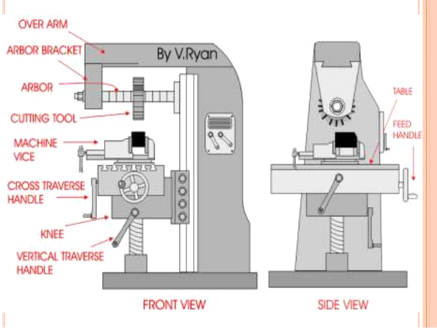
Figure 3: Horizontal milling Machine
2. Vertical Milling machine:
In this type of milling machine, the spindle is perpendicular to the work table.
It has all the movements of the table for proper setting and feeding the work.
Spindle head may be swivelled at an angle, permitting the milling cutter mounted on the spindle to work on angular surfaces.
In some machines, spindle can also be adjusted up or down related to work.
It is adopted for machining grooves, slots and flat surfaces.
5.2.4: Milling Processes:
1. Plane milling:
It is the process to get flat surfaces on the work piece in which the cutter axis and work piece are parallel. The primary motion is the rotation of the cutter. The feed is imparted to the work piece.
2. End milling:
This is the milling operation that is performed for producing flat surfaces, key slots, grooves or finishing the edges of the work piece with use of end milling cutter through vertical milling machine.
3. Slot milling:
This is also an important milling process which is used for operations for producing T-slots, plane slots and much other slot structure by using end milling cutter, T-slot cutter or slide milling cutter on vertical milling machine.
4. Angular milling:
Angular milling is one the machining technique in which operation of producing all types of angular cuts likes V-notches and grooves, serrations and angular surfaces by using double angular cutter on horizontal milling machine.
5. Form milling:
This machining process have operations of producing all types of angular cuts like V-notches and grooves, serrations and angular surfaces by double angular cutter on horizontal milling machining.
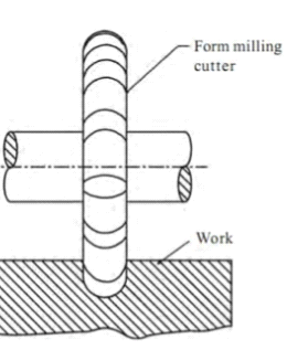
Figure 4: Form milling
6. Straddle milling:
This machining process have operations of machining two parallel surfaces simultaneous on a work piece by two or more side and face milling cutter on horizontal milling machine.
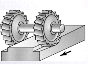
Figure 5: Straddle milling
7. Gang milling:
This is machining process to get distinct profiles on the work piece simultaneously with two or more cutters at one stretch by using different cutters on horizontal milling machine.
5.3.1: Introduction:
A numeric control system is a system in which the data handling, control, and response to input is determined by an on-board computer system at the machine tool.
5.3.2: Components of CNC:
Following are the components of CNC:
• Input device
• Machine control unit
• Machine tool
• Driving System
• Feedback devices
• Display system
5.3.3: Open Loop and Closed Loop System:
(a) In open loop system may overshoot or may not reach at desired process due to inertia, wear and tear, and friction, hence generates the greater probability of inaccurate machining process.
(b) Whereas, in closed loop system, the position sensors are used to correct the slide movement and achieve higher accuracy and repeatability.
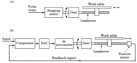
Figure 6:Open and closed loop System
5.3.4: Advantages of CNC:
1. The accuracy of the CNC machine ensures consistent product quality.
2. Increased production speed and increased efficiency.
3. CNC Machining is more cost effective.
4. One of the main advantages for the operators of CNC machines is safety.
5.3.5: CNC Machinig centre:
Machining centers are critical equipment for machining metal parts and components in addition to their primary purpose of die manufacture. ... Machining centers feature a computerized automatic tool change function. In general, an operator must exchange the tools on an NC machine tool.
The CNC machine tool center is an advanced manufacturing machine tool that can perform a variety of machining operations with high precision, high quality and high surface finish. A CNC machine tool center can perform drilling, milling and lathe operations.
5.3.6: Turning Centres of CNC:
Turning centres have multifunctional capabilities and multi-axis capabilities. This means that you might have a C-axis, Y-axis and driven tools on the turret to be able to perform not only turning but also milling, drilling and tapping operations.
Turning Centers perform rotating spindle operations while the Machining Center performs a turning type operation.
CNC Turning is a manufacturing process in which bars of material are held in a chuck and rotated while a tool is fed to the piece to remove material to create the desired shape.
A robot is a machine that can move and do certain tasks. Robots are controlled by a computer program or electronic circuitry. They may be directly controlled by humans. They may be designed to look like humans, in which case their behaviour may suggest intelligence or thought but they do not have feelings.
5.4.1: Robot Anatomy:
1. Joints and links:
The robot consists of sereis of joints and links. A robotic joints provides the relative motion between the two links of the robot. Each joints provide a certain degree of freedom of motion. Each joint is connected with two links, one is input and other is output link. This joints provide relative movement with input and ourput link. A robotic link is the rigid component of robotic manipulator. In most of the cases, only one degree of freedom is associated with each joint. Therefore the robots complexity can be classified according to according to total number of degree of freedom they posses.
5.4.2: Common robot Configuration:
A cartesian configuration, also called rectilinear, can move along three axis (x, y and z); the work area is therefore square. The arm links in this configuration are connected via linear joints.
This type of configuration features two horizontal joints and a cylindrical work area. It is not intended for work in multiple planes, but rather precision within one plane.
5.4.3: Application of robot in material handling:
• Materials handling, the movement of raw goods from their native site to the point of use in manufacturing.
• Their subsequent manipulation in production processes, and the transfer of finished products from factories and their distribution to users or sales outlets.
• Material-handling applications include material transfer and machine loading and unloading.
5.4.4: Application of robot for assembly and inspection:
In many automotive plants, robots are assembling smaller components like pumps and motors at high speeds. Often, robots are performing tasks like windshield installation and wheel mounting to increase through output.
Our inspection robot gathers data and uses artificial intelligence to alert your engineers. Reduce plant downtime with reliable data acquisition for preventative maintenance.
References:
1. Notes provided
2. Google websites
3. A. S. Sethia notes
4. Slide share